Maximum Controls MAX SUPER ARM 2300 Installation And Owner's Manual
Actuator arms
Hide thumbs
Also See for MAX SUPER ARM 2300:
- Manual (14 pages) ,
- Installation and owner's manual (56 pages)
Table of Contents
Advertisement
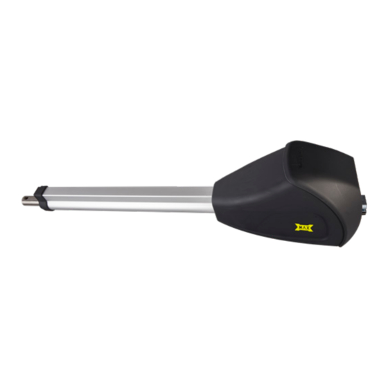
max super arm 2300
CONFORMS TO UL STD 325
UL CLASS - I, II, III, IV
CERTIFIED TO CAN/CSA STD
C22.2 NO. 247
Version 11a
Installation and Owners manual for
M
a
M
a
x
s
u
p
e
r
Residential / Commercial
Linear Gate Operators
www.max.us.com
max arm
SAFETY SENSORS REQUIRED
x
A
r
m
A
r
o s
e
m
o p
e n
2
3
0
0
Actuator Arms
M
a
C
x
o
A
n
r
t
m
B
r
o
o
x
l
c l
R M
L A
T A
S E
R E
E
A T
S E
L O
G G
/ C
J O
E N
O P
4009963
Advertisement
Table of Contents
Troubleshooting

Related Manuals for Maximum Controls MAX SUPER ARM 2300


Summary of Contents for Maximum Controls MAX SUPER ARM 2300
- Page 1 Installation and Owners manual for max arm max super arm 2300 Actuator Arms CONFORMS TO UL STD 325 SAFETY SENSORS REQUIRED UL CLASS - I, II, III, IV CERTIFIED TO CAN/CSA STD C22.2 NO. 247 Residential / Commercial Linear Gate Operators 4009963 www.max.us.com...
-
Page 3: Table Of Contents
Release Drive Rod Brackets Mounting Arm Pull Open Dimensions Push Open Dimensions mounting max super arm 2300 Release Drive Rod Brackets Mounting Arm Pull Open Dimensions Push Open Dimensions UL 325 2018 MAX Arm and MAX Super Arm V11a... - Page 4 Max gate length per gate..157.4 in Operating Temperatures..-20°C ~+50°C 4.5” Max Weight/ Power supply..24 VDC max super arm 2300 Length Max speed..7 in/sec Max stroke length..19.8 in Max traction and pressure force per leaf..4500 N Rated torque per leaf..1500 N 8ft 12ft 16ft 20ft Min = 37”...
-
Page 5: Important
important BEFORE attempting to install, operate or maintain the operator, you must read and fully understand this manual and follow ALL safety instructions. DO NOT attempt repair or service of your gate operator unless you are an Authorized Service Technician. GATE CONSTRUCTION INFORMATION Vehicular gates should be installed in accordance with ASTM F2200: Standard Specification for Automated Vehicular Gate Construction. -
Page 6: Ul 325 Compliant Installation Requirements
ul 325 compliant installation requirements a) Install the gate operator only when: a) N’installez l’ouvre-barrière que si : 1) The operator is appropriate for the construction of the gate and the usage Class of the gate, 1) l’ouvre-barrière est approprié pour la structure et la classe d’utilisation de la barrière; 2) All openings of a horizontal slide gate are guarded or screened from the bottom of the gate to a minimum of 1.83 m (6 ft) above the ground to prevent a 57.2 mm (2-1/4 inch) diameter sphere from passing through the openings anywhere in the gate, and in that portion of the adjacent fence that the gate covers in the open position,... - Page 7 ul 325 compliant installation requirements continued g) The Stop and/or Reset button must be located in the lineof-sight of the gate. Activation of the reset control shall not cause the operator to start. g) Le bouton d’arrêt, le bouton de réenclenchement ou ces deux boutons doivent être situés dans le champ de visibilité de la barrière. L’activation des commandes de réenclenchement ne doit pas mettre en marche l’ouvrebarrière.
-
Page 8: Important Safety Imformation
important safety information IMPORTANT SAFETY INSTRUCTIONS WARNING – To reduce the risk of injury or death: INSTRUCTIONS DE SÉCURITÉ IMPORTANTES AVERTISSEMENT – Pour réduire les risques de blessures et de mort : 1. READ AND FOLLOW ALL INSTRUCTIONS. 1. LISEZ ET SUIVEZ TOUTES LES INSTRUCTIONS. 2. -
Page 9: Ul 325 Model Classifications
ul 325 model classifications AUTHORIZED PERSONNEL ONLY CLASS I CLASS III Residential Vehicular Gate Operator - A vehicular gate operator Industrial/Limited Access Vehicular Gate Operator - A (opener or system) intended for use in a home of one to four vehicular gate operator (opener or system) intended for uses single family dwellings, or a garage or parking area associated in an industrial location, loading dock area or other location... -
Page 10: Gate Safety Installation
gate safety installation Weld a horizontal bar across entire gate on any installation for strength. DO NOT weld the crossbar on just a few pickets, or they could bend. Make sure that the operator is mounted level or it will not function properly. Arm should be mounted at least 12 inches above the ground. Make sure there is slack in the operator cable. - Page 11 gate safety installation DO NOT install on uphill or downhill gates. Install on back side Moving Gate Can Cause Serious Injury or Death KEEP CLEAR! Gate may move at any time without prior warning. Do not let children operate the gate or play in the gate area.
-
Page 12: Intended Use Of Swing Gate Operator
intended use of swing gate operator The operator is intended for use on a VEHICULAR slide gate ONLY. It is intended to be used WITH appropriate entrapment protection safety devices and in-ground vehicle loop detection system. This operator has a inherent entrapment protection system and requires additional external monitored entrapment protection devices (Non-contact Photo sensors or contact sensing edges) for each entrapment area prior to gate operation. -
Page 13: Step-By-Step Installation
Mount your selected arm to the gate. See MAX Arm - pages 25-27 MAX Super Arm 2300 - pages 28-30. DUAL GATE OPERATORS: When installing dual gate operators, also refer to page 24. mount control box Mount the control box as near as possible to the actuator arm. Avoid drilling holes in the side or top of the box. -
Page 14: Ac Input Power Only
ac input power ONLY NOTE: IF solar power is being installed, see page 34 for wiring. CAUTION: Make sure circuit breaker is OFF from incoming Choose either 115V or 230V setting on input AC power selector switch. AC input wire BEFORE wiring! Wire desired input AC power wire to power terminal. - Page 15 OVER PORT LOAD LOAD OPENING CLOSING Motor 2 connects the same as Motor 1. OBD PORT LIMIT 1 BLACK BOX RESET MAXIMUM CONTROLS Motor 2 MOTOR 2 (Bi-Parting Gates ONLY) DSP ARM CONTROLLER ON/OFF LIMITS ALARM BATTERY Connection LIMIT 2...
-
Page 16: Settings: Gate/Id Plug/Operator
OVER PORT LOAD LOAD MOTOR 1 OPENING ENING CLOSING LIMITS LIMIT 2 OBD PORT BLACK BOX LIMIT 1 MAXIMUM CONTROLS RESET MOTOR 2 DSP ARM CONTROLLER LIMITS LIMIT 2 ON/OFF ALARM BATTERY MOTION CONTROL PROGRAMMING GATE OPEN ID PLUG ERROR... -
Page 17: Limit Switch Adjustments
limit switch adjustments Adjust the limit switches for OPEN and CLOSE gate Limit LEDs positions for your selected MODEL OPERATOR and LIMIT 1 OPENING DIRECTION on the next 3 pages. Mode B With gate in the exact Close and then OPEN MOTOR 1 LIMIT 2 positions respectively, adjust each limit until the... - Page 18 11. Rotate CLOSE limit screw until BEEP is heard. NOTE: Rotate CLOSE limit screw in “MINUS” direction for gate to close LESS. close Rotate CLOSE limit screw in “PLUS” direction for gate to close FURTHER. c l o CAUTION: If BEEP is NOT heard, readjust front bracket position. NOTE: If 2 consecutive beeps are heard when moving gate to CLOSED position, BEEP then adjust gate to FIRST beep position.
- Page 19 11. Rotate CLOSE limit screw until BEEP is heard. NOTE: Rotate CLOSE limit screw in “MINUS” direction for gate to open LESS. close Rotate CLOSE limit screw in “PLUS” direction for gate to open FURTHER. c l o CAUTION: If BEEP is NOT heard, readjust front bracket position. NOTE: If 2 consecutive beeps are heard when moving gate to OPEN position, BEEP then adjust gate to FIRST beep position.
- Page 20 12. Re-lock Manual release. MOTION CONTROL 13. Learn newly adjusted limits on control box. Push the OPEN button, gate will open and learn open limit. Push the CLOSE button, gate will close and learn close limit. NOTE: Gate may not ramp down when approaching limits while “LEARNING” gates but will ramp OPEN CLOSE STOP...
-
Page 21: Entrapment Protection Locations (List Of Sensors)
Sensors - UL325 2018 The following is a list of recommended safety devices for the MAX Strong Arm & MAX Super Arm 2300 (sold separately). Miller Edge R-Band Wireless Edge Unit Omron E3K-R10K4-10R Photocell (Reflector) P/N: RB-G-RX10 &... -
Page 22: Entrapment Protection Wiring (Test Photo Cls Nc Sensor)
CLOSE entrapment protection wiring LOCK MAGLOCK DELAY Normally Closed Photocells OPEN ONLY NC Learned monitored input Automatically monitored PHOTO CLS NC IMPORTANT: NC MONITORED OPEN / CLS NC 2.5 sec sensors MUST be powered by the Additional learned monitored input Power Opening Direction 12VDC OUT on the UL Sensor N.C. -
Page 23: Adjust Erd Reverse Sensor
Adjust ERD Reverse sensor The ERD Sensor - Electronic Reversing Device (Type A) MUST be adjusted for the OPEN and CLOSE gate cycles. When the gate encounters an obstruction during the CLOSE cycle, it will reverse to the open position and PAUSE the gate. An input command (press remote button or exit loop) is needed BEFORE the gate will reset and close again. -
Page 24: Dsp Controller Board Settings
Turned OFF - NO Maglock installed. LIMITS LIMIT 2 OBD PORT At this point, gate will remain CLOSED. BLACK BOX LIMIT 1 MAXIMUM CONTROLS RESET Set to 1.5 sec or 2.5 sec - You MUST MOTOR 2 DSP ARM CONTROLLER LIMITS LIMIT 2... - Page 25 a n d...
- Page 26 LOAD OPENING CLOSING LIMITS LIMITS LIMIT 2 • MODE B DIP-switch 4 MUST be OFF. OBD PORT BLACK BOX RESET MAXIMUM CONTROLS ONTROLS MOTOR 2 OR 2 LIMITS LIMITS DSP ARM CONTROLLER ONTROLLER ON/OFF ON/OFF • MODE B DIP-switch 6 MUST be set to chosen operator type.
- Page 27 mounting max arm release drive rod Lift key plate. Insert key and turn 90°. Drive rod can now be pulled out. D r i brackets Pull Open Rear Bracket Sleeve Anchors Front (Not Supplied) Rear Pin Bracket Rear Bracket Assembly Bolt or weld to gate.
- Page 28 mounting arm Gate must be in good working condition before the actuator arm can be installed. Determine what direction the actuator arm will open the gate: “PULL OPEN” or “PUSH OPEN” Installation (See next page). See the “GATE SAFETY and REQUIREMENTS” in front of this manual (pages 3-8) for mounting requirements and limitations.
- Page 29 pull open dimensions Closed 2.5” 60.3” Max DO NOT Fully Extend Drive Rod 39” Option 1 7” 5” 60.3” Option 2 8” 6” 60.3” Option 3 7.5” 7.5” 60.3” When “A” and “B” are similar dimensions, smoother Max Weight/ gate operation and reduce motor strain occurs. Length 8ft 12ft 16ft 18ft Minimum distance...
- Page 30 mounting super arm 2300 release drive rod Insert key and turn 90°. D r i Lift back cover. Drive rod can now be pulled out. brackets Front Pull Open Rear Bracket Bracket Sleeve Anchors Bolt (Not Supplied) Bolt Bolt or weld to gate. Mounting Hardware (Not Supplied) Rear Bracket...
- Page 31 mounting arm Gate must be in good working condition before the actuator arm can be installed. Determine what direction the actuator arm will open the gate: “PULL OPEN” or “PUSH OPEN” Installation (See next page). See the “GATE SAFETY and REQUIREMENTS” in front of this manual (pages 3-8) for mounting requirements and limitations.
- Page 32 pull open dimensions 1.5” 19.88” Max Table in inches 54.72” Max DO NOT Fully Max. gate width 5.51 6.29 7.87 8.66 9.44 C/C1 per gate Extend Drive Rod D° 48.9/14.2 50.1/15.4 51.7/16.9 53.5/18.7 54.5/19.8 54.5/19.7 6.29 137.7 91° 93° 102° 110°...
-
Page 33: Additional Features
PORT LOAD LOAD MOTOR 1 OPENING CLOSING LIMITS LIMIT 2 OBD PORT 24/7 access. Gate fully opens. BLACK BOX LIMIT 1 MAXIMUM CONTROLS RESET MOTOR 2 DSP ARM CONTROLLER LIMITS ON/OFF LIMIT 2 ALARM BATTERY PROGRAMMING MOTION CONTROL GATE OPEN... -
Page 34: Open / Stop / Close Inputs
OVER PORT LOAD LOAD MOTOR 1 OPENING CLOSING LIMITS LIMIT 2 OBD PORT BLACK BOX LIMIT 1 MAXIMUM CONTROLS MOTOR 2 3-Button LIMITS DSP ARM CONTROLLER LIMIT 2 ON/OFF External Alarm Reset Button BATTERY PROGRAMMING MOTION CONTROL GATE OPEN Station... - Page 35 additional features lock to close Single Gate Gate must have a positive stop in closed position (such as a trim piece on a gate post that overlaps gate). Mode B DIP-Switch 3 MUST be ON. Post with positive stop Close Positive Stop NOTE: PULL OPEN illustrated...
-
Page 36: Solar Power
Maximum Controls offers a solar power enclosure to power the control box and solar panel (Sold separately). Mount solar power enclosure underneath control box. Connect solar adapter cable to MODULE PORT. DO NOT connect AC power to the toroid box. -
Page 37: Obd Port Black Box
INFO : PRI_CIO: Communica on Established LIMITS LIMIT 2 OBD PORT BLACK BOX Fri 07/11/2014 10:57:38 ENTRAP : PRI_MC: Photo Cell Deac vated LIMIT 1 MAXIMUM CONTROLS RESET MOTOR 2 LIMITS DSP ARM CONTROLLER LIMIT 2 ON/OFF Fri 07/11/2014 10:57:34... -
Page 38: Gate Cycling Troubleshooting
gate cycling troubleshooting Gate Symptom Solutions (what to check) Gate moves slowly. • Check if GATE SPEED rotary dial is set to MAX position (LED on). • Gate may be too heavy for operator (check manual for maximum gate weight for your model operator). •... -
Page 39: Dsp Board Troubleshooting
MOTOR 1 8. MOTOR OVERLOAD OPENING CLOSING LIMITS LIMIT 2 22. ON/OFF BATTERY OBD PORT BLACK BOX LIMIT 1 23. ANTI-TAILGATE MAXIMUM CONTROLS RESET MOTOR 2 10. OBD PORT LIMITS DSP ARM CONTROLLER 24. OPEN LEFT LIMIT 2 ON/OFF BATTERY ALARM 11. - Page 40 troubleshooting continued DSP Board LED Normal Solution(s) for Problem Condition Problem Condition “ID PLUG” LED is FLASHING and • Insert ID PLUG module that is tethered to chassis into “ID PLUG” connector. board beeping “SOLAR MODE” LED is ON • Operator is being powered by solar panel ONLY.
- Page 41 co��ON SENSOR 'WIRINCi 0- - - - 0"4RO,,.., E3IC-RIOIC4 Photocell (Reflector) CLDSING Direction NOTE: DO NOT NOTE: To meet the UL 325 2018 standard, use 1 OK Resisitor Type 81 Non-Contact sensor entrapment included with protection device MUST be MONITORED photocell.
-
Page 42: Emx Irb-Mon (Single Gate)
Photocell (Thru-Beam) CLOSING Direction emx irb-mon Single Gate Operator Transmitter Receiver To PHOTO CLS NC (TX) (RX) CLOSING direction Thru-Beam and 12VDC OUT Input IMPORTANT: Photocells MUST Gate Closed be in alignment or fault will Control Box occur. Green LED will remain To Control Box ON receiver when in proper 12VDC OUT Input... -
Page 43: Emx Irb-Mon (Dual Gates)
Photocell (Thru-Beam) CLOSING Direction emx irb-mon Dual Gate Operators To PHOTO CLS NC and Transmitter Receiver (TX) Entrapment Area (RX) 12VDC OUT Input CLOSING direction Thru-Beam EMX IRB-MON Photocell CLOSING direction Photocell Gates Closed Control Box To 12VDC OUTPUT Input IMPORTANT: Photocells MUST be in alignment or fault will occur. - Page 44 A4ILLER RB.4./111,/D A40/lll,/ITORED �IRELESS GNU ANT ■-1 CHECK � :-,, Channel 1 & 2 transmitters RBAND Receiver DIP-Switches MUST be programmed by "' 1-0N RBAND receiver. See below or 2-0FF "' Miller Edge Wireless RBAND "' 3-0N instruction sheet to program "' "' 4-0N...
-
Page 45: Manually Release Gate
BEFORE manually releasing gate! of the gate to move it. responsible for the KEY availability. max Super Arm 2300 Insert key and turn 90°. Lift back cover. Gate can now be manually moved. UL 325 2018 MAX Arm and MAX Super Arm V11a... - Page 46 UL 325 2018 MAX Arm and MAX Super Arm V11a...
- Page 47 UL 325 2018 MAX Arm and MAX Super Arm V11a...
-
Page 48: 2018 Maximum Controls Llc
Installation and Owners manual for max arm max super arm 2300 Actuator Arms CONFORMS TO UL STD 325 SAFETY SENSORS REQUIRED UL CLASS - I, II, III, IV CERTIFIED TO CAN/CSA STD C22.2 NO. 247 Residential / Commercial Linear Gate Operators 4009963 Maximum Controls LLC.
Need help?
Do you have a question about the MAX SUPER ARM 2300 and is the answer not in the manual?
Questions and answers