Table of Contents

Subscribe to Our Youtube Channel
Related Manuals for Roughneck 28481

Summary of Contents for Roughneck 28481
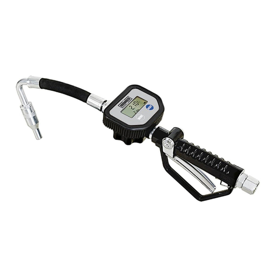
- Page 1 DIGITAL OIL CONTROL VALVE OWNER’S MANUAL WARNING: Read carefully and understand all INSTRUCTIONS before operating. Failure to follow the safety rules and other basic safety precautions may result in serious personal injury. Item # 28481...
-
Page 2: Technical Specifications
Thank you very much for choosing a Roughneck™ Product! For future reference, please complete the owner’s record below: Model: _______________ Purchase Date: _______________ Save the receipt, warranty and these instructions. It is important that you read the entire manual to become familiar with this product before you begin using it. -
Page 3: Specific Operation Warnings
6. Do not overreach. Keep proper footing and balance at all times to prevent tripping, falling, back injury, etc. 7. DO NOT use the equipment when tired or under the influence of drugs, alcohol, or medication. A moment of inattention while operating this equipment may result in serious personal injury. 8. -
Page 4: Installation
INSTALLATION Typical installation refers to Fig.1 (typical installation). 1 Air inlet 2 Air shut-off valve 3 Oil pump 4 Fluid shut-off valve 5 Meter 6 Hose reel 7 Control valve NOTE: The above typical installation is only for reference. It may be different from your actual system design. WARNING: If this is a new installation, or if the oil in the lines is contaminated, flush the lines before you install the control valve. -
Page 5: Installation Process
2. INSTALLATION PROCESS WARNING: To reduce the risk of serious injury, the pressure release procedure should be followed very carefully. Follow the PRESSURE RELIEF PROCEDURE in OPERATION INSTRUCTIONS section. WARNING: Make sure the whole system is clean before installing/replacing a new control valve. No impurities or contaminants should enter the control valve. -
Page 6: Pressure Relief Procedure
pressure of the control valve you are using or of the lowest rated component in your system. 1. PRESSURE RELIEF PROCEDURE WARNING: Skin injection hazard: The equipment stays pressurized until pressure is manually relieved. To reduce the risk of serious injury from pressurized fluid, fluid from the valve or splashing fluid, follow this procedure whenever you: ➢... -
Page 7: Calibration Procedure
③. When desired measurement unit is displayed, press “MENU” and hold about 1second or the digit stops blink to quit the setting mode. Solution 2 ①. Move the flashing display to Zone② by pressing “MENU”, then press “RESET” to choose measurement unit. -
Page 8: Troubleshooting
③. Insert a 3.6V ER14250 battery into the battery compartment. Install the battery according to the direction of polarity+”&“-” indicated and insert the end of anode “+” first. ④. Replace the battery cover (part# 3-11). TROUBLE SHOOTING WARNING: Relieve pressure before you check or service any system equipment. Problem Possible Cause Corrective Action... -
Page 9: Diagrams And Parts List
MAINTAINANCE Transportation When the control valve is in transit, do not expose the control valves to direct sunlight and avoid rain, falling, corrosive substance, etc. Storage ①. Store the control valve in a dry place with good ventilation. Do not expose it to excessive heat, humidity, or sunlight. -
Page 10: Warranty
Part No. Description Part No. Description Swivel Main Circuit Board Handle Front Label Trigger Lock Screw Trigger Screw 1-5* O-ring O-ring Screw 3-10 Seat 3-11 Battery Cover 3-12 Spring 1-9* Seat 3-13* Battery 1-10 Spring 3-14 Screw 1-11 Seat 3-15 Shaft 1-12 Spring...
Need help?
Do you have a question about the 28481 and is the answer not in the manual?
Questions and answers