
Related Manuals for Workhorse Mach Series

Summary of Contents for Workhorse Mach Series
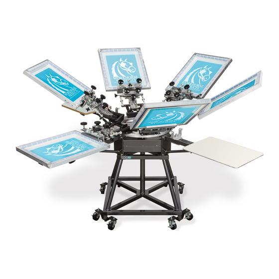
- Page 1 Owner’s Manual Mach Series 3730 E. Southern Avenue, Phoenix, AZ 85040 USA 800-778-8779 Workhorseproducts.com...
-
Page 2: Table Of Contents
Table of Contents I. Introduction …………..…………………………...………………….……….…….……….. 3 II. Specifications …..……………..………………………...………….………..………….…. 4 III. Parts for Assembly …..……………..……………………….….………….…….………. 5 IV. Assembly Step 1: Inserting Levelers and Casters ……..……………………….…….……… 6 Step 2: Installing the Print Head …………………………………….….…….……. 7 Step 3: Installing the Print Arms ……….………………..………………...….……. 8 Step 4: Attaching the Platens …………………….…………..…………….…..……. -
Page 3: Introduction
The Importance of the Owner’s Manual: The purpose of the Owner’s Manual is to familiarize you with the parts and operations of the Mach Series. There are step-by-step instructions to assemble the press, accompanied with links to videos for further assis- tance. -
Page 4: Specifications
Specifications M-86-O M-44-M 8 Color, 6 Station 4 Color, 4 Station Max Screen: 21" (53CM) Max Screen: 32" (81CM) Dimensions: 111” x 34-36” Dimensions: 103” x 34-36” M-64-O M-88-O 6 Color, 4 Station 8 Color, 8 Station Max Screen: 23" (58CM) Max Screen: 26"... -
Page 5: Parts For Assembly
The quantity of parts differs depending on the specific model being assembled. In this manual a 6 Color/ 4 Station Mach Series Manual Press is being assembled. The quantity of parts will not match if assembling another model of the product. -
Page 6: Assembly
Assembly Step 1: Inserting levelers/casters. Tools needed: Parts needed: 3/4” Wrench and 4 x Levelers/Casters Socket Base 3/4” Wrench and Socket 1. Install the leveling nut onto the leveling bolt until it’s 1” from the bolt head. When installing the levelers ensure that they are all the same height. -
Page 7: Step 2: Installing The Print Head
Assembly Step 2: Installing the print head. Parts needed: 12 x 1/2” Flat Washers 6 x Stop Bolts 12 x Lock Nuts 12 x Hog Rings 12 x Nylon Nettings 1. Raise the print head and insert 3. -
Page 8: Step 3: Installing The Print Arms
Assembly Step 3: Installing the print arms. Tools needed: Parts needed: Hammer 16 x Hex Bolts (1.5” x 25mm) 3/4” Socket 16 x Flat Washers (1/2”) Wrench 8 x Roll Pins 2. Insert a bolt (1.5”x 25mm) 1. -
Page 9: Step 4: Attaching The Platens
Remember, don’t adjust the bolts and nuts located on the support arms. They are factory set for proper leveling and alignment. One of the many advantages of the Mach Series is that when it’s manufactured it’s also fully assembled, making it leveled and inspected at the factory. This quality control process is to ensure success when assembling the press on location. -
Page 10: Print Head And Micro Adjustments
Print Head and Micro Adjustments (A) Off Contact Adjustment Knob (B) X and Y Micro Adjustments (C) Micro Lockdown Knobs (D) Side-to-Side Adjustment (E) Off Contact Jam Knob (F) Screen Lockdown Knobs (G) Off Contact Clamp & Screen Holder (H) Screen Tilt Adjustment (H1) Screen Tilt Jam Nut (H2) Screen Tilt Ring (I) Off Contact Foot Pad... - Page 11 Print Head and Micro Adjustments (H2) (H1) (A) Off Contact Adjustment Knob (E) Off Contact Jam Knob (H) Screen Tilt Adjustment (B) X and Y Micro Adjustments (F) Screen Lockdown Knobs (H1) Screen Tilt Jam Nut (C) Micro Lockdown Knobs (G) Off Contact Clamp &...
-
Page 12: Maintenance And Troubleshooting
Maintenance and Troubleshooting The Mach Series does not require much maintenance, but periodic lubrication and cleaning will ensure smooth opera- tion and extended life of the components. Wipe the press daily to remove spray adhesive and lint. Do not let the spray adhesive and lint accumulate. -
Page 13: Parts List
Parts List Description Part no. Complete arm assembly. Includes everything to add a print station 21001R Nylon Registration bolt kit. Includes Lock nut Package of 12 73007R Spring and Ext. Hog Ring kit. Package of 12 71010R NOTE: these should be replaced annually !! Y-axis Adjusting assy. -
Page 14: Limited Warranty
Equipment manufactured or sold by Workhorse Products is warranted against defects in workmanship and materials for a period of one year from receipt by cus- tomer. All warranties initiate from date of shipment to original customer. Replacement parts are covered for the term of the equipment warranty period.
Need help?
Do you have a question about the Mach Series and is the answer not in the manual?
Questions and answers