Advertisement
1.0 INTRODUCTION
The NALTM unit is supplied with a pre-wired terminal box and an IP44 rated,
class B (unit sizes 100-160) or class F (unit sizes 200-315) insulated motor. The
fans are designed to convey clean air with a maximum temperature of up to
60°C (NALTM-315H up to 55°C only).
Do not operate the fan in the presence of inflammable vapours (alcohol etc). An
adequate supply of fresh air must be provided if the fan is to be fitted in a room
with a gas burning appliance which is not of the balance flue type.
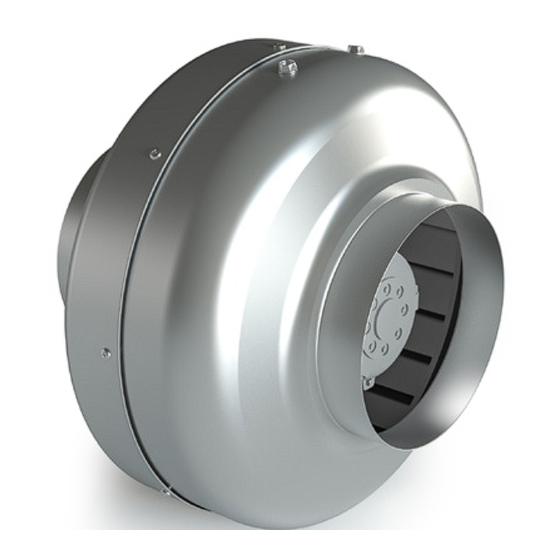
Figure 1. Unit Drawing
Code Description:
NALTM-100H
1
2 3
1. NALTM - Centrifugal Metal Tube Fan Range
2. 100 - Case Size
3. No Suffix - 50Hz 230V
H - 60Hz 220V
2.0 HANDLING
Always handle the fans carefully to avoid damage and distortion. Care should
be taken to ensure that any slings used for lifting purposes do not damage the
casing, connection box, impeller or inlet cone.
3.0 INSTALLATION
Installation must be carried out by a competent person in accordance with the
appropriate authority and conforming to all statutory and governing regulations
(e.g. IEE, CIBSE etc.).
From the fan Rating Plate, observe the weight of the unit and select the
mounting position and structure that can support the unit.
These fans are not for stand-alone use. They are designed to be incorporated
into ducted systems, machines or where safe (i.e. operation has been ensured by
providing applicable protection to moving parts).
This unit is not designed for external use. Before installing ensure the impeller is
running freely and there are no obstructions to the airflow
A robust mounting foot is available as an accessory, to ease installation.
IMPORTANT
For good EMC engineering practice, any sensor cables or
switched live cables should not be placed within 50mm of other
cables or on the same metal cable tray as other cables.
Isolation - Before commencing work, make sure that the unit,
switched live and any controls are electrically isolated from the mains
supply.
Please note that this product must be earthed.
nuaire.co.uk
029 2085 8400
NALTM 50 & 60HZ
Metal Cased Centrifugal Fans
Installation and Maintenance
4.0 DIMENSIONS (mm) & Weights (kg)
Figure 2. Unit Dimensions
50 Hz Code
60 Hz Code
NALTM-100
NALTM-100H
NALTM-125
NALTM-125H
NALTM-150
NALTM-150H
NALTM-160
NALTM-160H
NALTM-200
NALTM-200H
NALTM-250
NALTM-250H
NALTM-315
NALTM-315H
5.0 ELECTRICAL WIRING
Electrically isolate unit before commencing any work. Ensure that the voltage
and frequency of the electrical supply match the information stated on the
Rating Plate on the unit. Wire the unit as shown in the wiring diagram. On
connecting the electrical supply, ensure that the airflow direction corresponds
with the direction of the airflow arrow sited on the unit.
Figure 3. Wiring diagram
BROWN
BLUE
MOTOR
BLACK
YELLOW-GREEN
Electrical Note: Because the run and start currents depend upon the duty and
associated duct work of an individual unit, the values quoted in the table are
nominal.
Run currents will be exceeded if the unit is operated beyond the operating curve
shown in the performance catalogue.
18. 03. 19. Leaflet Number 671775
The EMC Directive
2014/30/EU
The Low Voltage
Directive
2014/35/EU
A
B
C
D
E
Weight
241
98
196
150
23
241
123
198
144
27
332
147
212
166
23
332
157
221
175
23
333
198
223
173
25
333
248
206
152
27
401
312
230 180
25
L N
3
3
5
5
5
6
8
1
Advertisement
Table of Contents

Subscribe to Our Youtube Channel
Related Manuals for NuAire NALTM Series


Summary of Contents for NuAire NALTM Series
-
Page 1: Electrical Wiring
Isolation - Before commencing work, make sure that the unit, switched live and any controls are electrically isolated from the mains supply. Please note that this product must be earthed. nuaire.co.uk 029 2085 8400 18. 03. 19. Leaflet Number 671775... - Page 2 The product warranty applies to the UK mainland and in accordance with Clause 14 of our Conditions of Sale. Customers purchasing from outside of the UK should contact Nuaire International Sales office for further details. 8.0 AFTER SALES ENQUIRIES For technical assistance or further product information, including spare parts and replacement components, please contact the After Sales Department.
Need help?
Do you have a question about the NALTM Series and is the answer not in the manual?
Questions and answers