Table of Contents
Advertisement
Advertisement
Table of Contents

Related Manuals for Spellman LORAD LPX-200

Summary of Contents for Spellman LORAD LPX-200
- Page 2 IS HIGHLY RECOMMENDED. WWW.SPELLMANHV.COM Copyright 2000, Spellman High Voltage Electronics Corporation. All Rights Reserved. This information contained in this publication is derived in part from proprietary and patent data. This information has been prepared for the express purpose of assisting operating and maintenance personnel in the efficient use of the model described herein, and publication of this information does not convey any right to reproduce it or to use it for any purpose other than in connection with installation, operation, and maintenance of the equipment described.
- Page 3 This document is copyrighted by LORAD. No part of this document may be reproduced, transmitted, or copied without the express written permission of: Spellman Valhalla 1 Commerce Park Valhalla, NY 10595 Phone: +1 914 686-3600 Fax: +1 914 686-5424 www.spellmanhv.com LPX-200 Industrial Imaging System Operator’s Manual...
- Page 4 LPX-200 Industrial Imaging System This Page Is Intentionally Blank Table of Contents...
-
Page 5: Table Of Contents
LPX-200 Industrial Imaging System Contents Chapter INTRODUCTION & GENERAL INFORMATION INTRODUCTION ..............1-1 Intended Use ................. 1-1 SYSTEM OVERVIEW ............1-1 The Control Unit ..............1-2 The Tubehead ............... 1-2 The Cooling Unit (liquid-cooled units only) ............. 1-2 Legend - LPX-200 X-ray System .......... 1-3 MANUAL OUTLINE .............1-4 Chapter 1: Introduction &... - Page 6 LPX-200 Industrial Imaging System Chapter PREPARATION FOR USE & SHIPMENT UNPACKING INSTRUCTIONS ........... 2-1 Reshipment Guidelines ............2-1 Transporting the Unit ............2-2 EQUIPMENT CHECKLISTS..........2-3 Checklist - Tubehead ............2-3 Checklist - Standard Equipment ........... 2-3 Checklist - Optional Equipment ........... 2-3 WARNINGS LABELS &...
- Page 7 LPX-200 Industrial Imaging System Chapter LPX-200 X-RAY CONTROLS & INDICATORS INTRODUCTION ..............4-1 Overview - Control Unit ............4-1 Legend - LPX-200 Control Unit ........... 4-1 THE LIQUID CRYSTAL DISPLAY SCREENS ..........4-2 The Message / Mode LCD Display Screen ......4-3 FRONT PANEL CONTROLS AND INDICATORS ........4-4 The MAINS Switch ..............
- Page 8 LPX-200 Industrial Imaging System Chapter LPX-200 ROUTINE UPKEEP & CARE INTRODUCTION ..............6-1 INSPECTION CHECKLISTS ..........6-1 Tubehead Checklist .............. 6-1 Control Unit Checklist ............6-2 Cooling Unit Checklist ............6-2 Interconnecting Cables & Hose Checklist ......6-2 CLEANING THE LPX-200 X-RAY UNIT ............6-3 Required Cleaning Materials ..........
-
Page 9: Introduction & General Information
Industrial Imaging System Chapter 1: Introduction and General Information INTRODUCTION This manual describes the LORAD LPX-200 Portable Industrial X-ray Unit and explains the procedures to properly set up, inspect, operate, and maintain this system. Intended Use The LPX-200 is designed to meet the needs of the commercial NDT user. -
Page 10: The Control Unit
LPX-200 Industrial Imaging System The Control Unit The Cooling Unit (liquid-cooled units only) The radiographer uses the Control Unit to set the radiographic exposure parameters, and to activate/deactivate x-ray The Cooling Unit dissipates heat generated at the anode of the emissions from the Tubehead. -
Page 11: Legend - Lpx-200 X-Ray System
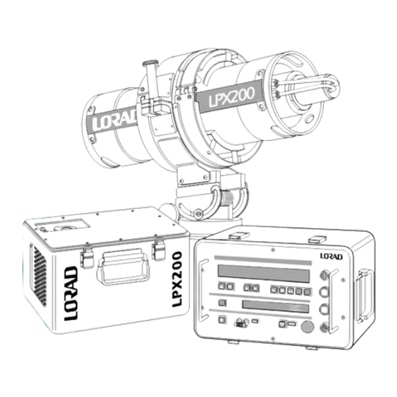
LPX-200 Industrial Imaging System Legend - LPX-200 X-ray System Use the following legend as a reference for parts idnetification. Exposure Technique LCD Display Lockout Keyswitch Message LCD Display Tubehead Anode Power Connector 10. Tubehead Coolant Hose Fittings Tubehead Connector 11. Tubehead Gas Pressure Gauge Cooler Connector 12. -
Page 12: Manual Outline
Chapter 4 details the controls and indicators on the LPX-200 LORAD LPX-200 Portable X-ray Unit. The following Control Unit. Refer to this chapter during use for operational paragraphs describe the arrangement of this manual and the details. - Page 13 LPX-200 Industrial Imaging System SAFETY SUMMARY Use the following summary as a checklist to assure comprehension of the safety indicators. When properly installed, maintained, and operated, X-ray equipment can be used effectively and safely. If any NOTE: component of this unit is incorrectly installed, and/or operated An essential operating procedure, condition, or by unqualified personnel, or if the maintenance schedule is statement, which must be observed to ensure proper...
-
Page 14: Badges
LPX-200 Industrial Imaging System Radiation Hazard Operation This equipment generates X-radiation at levels that can be Equipment must be operated at correct source voltage and lethal. This unit must only be operated by personnel that are frequency, and must never be left running unattended. The certified and experienced in industrial x-ray generation. -
Page 15: Preparation For Use & Shipment
LPX-200 Industrial Imaging System Chapter 2: Preparation for Use and Shipment UNPACKING INSTRUCTIONS Pack the Control Unit in a container rated for 60 lbs. Surround the Control Unit with a MINIMUM of 2" The LPX-200 X-ray Unit is shipped in a single wooden of shock absorbent packing material (sheet or loose container. -
Page 16: Transporting The Unit
LPX-200 Industrial Imaging System Transporting the Unit When transporting by commercial carrier (i.e., truck, rail, Removeable etc.), select the shipping method and carrier on the basis of safe shipment, especially when shipping the fragile Tubehead Assembly. Distinctly mark the Tubehead carton on all sides with labeling which provides the carrier the following information: N Contents contains fragile glass instrumentation... -
Page 17: Equipment Checklists
LPX-200 Industrial Imaging System EQUIPMENT CHECKLISTS Checklist - Standard Equipment The following checklists outline the standard and optional ❏ Control Unit, Digital (1) ____ 3-000-3074 equipment of the LPX-200 X-ray Unit. After unpacking the unit, and completing a thorough visual inspection, compare ❏... -
Page 18: Warnings Labels & Control Numbers
LPX-200 Industrial Imaging System WARNINGS LABELS & CONTROL NUMBERS Control Tag Each assembly of the LPX-200 X-ray System is equipped with an I.D. tag (Control Tag) providing the serial number, description, and part number. This data is used for identification, if warranty or service information is needed, and will be requested when contacting LORAD regarding the Warning Label apparatus. -
Page 19: Specifications
LPX-200 Industrial Imaging System SPECIFICATIONS The following tables illustrate the physical, operational, and environmental specifications for each component of the LPX-200 System. Conformance with these specifications ensures maximum system performance, and reduces the chances of mechanical breakdown and personnel hazard. Specifications - General System The following outlines the general operating and ❏... -
Page 20: Specifications - General Tubehead
LPX-200 Industrial Imaging System Specifications - General Tubehead DIRECTIONAL TUBE HEAD DIRECTIONAL TUBE HEAD The following outlines the general operating specifications of the Tubehead Assembly. ❏ Physical Specifications _____ Water Cooled: 8.5" dia. x 26.5" length - 32lbs (approx); Air Cooled: 8.5"... -
Page 21: Specifications - Control Unit
LPX-200 Industrial Imaging System Specifications - Control Unit Specifications - Cooling Unit Below are the physical and operating specifications of the Below are the operating and physical specifications of the Control Unit. Included are the physical dimensions, and the Cooling Unit. operating indicators and controls. - Page 22 LPX-200 Industrial Imaging System THIS PAGE IS INTENTIONALLY BLANK Chapter 2: Preparation for Use and Shipment...
-
Page 23: Installing The Lpx-200 X-Ray System
LPX-200 Industrial Imaging System Chapter 3: Installing the LPX-200 X-ray System PRE-OPERATIONAL Check - Cooling Unit CHECKS & INSPECTION This check verifies the integrity of the Cooling Unit (liquid The following paragraphs outline the steps to properly check cooled tubeheads only). and inspect the LPX-200 X-ray unit. -
Page 24: System Set Up Procedures
LPX-200 Industrial Imaging System SYSTEM SET UP PROCEDURES Make the External Interlock connection: N If available, connect the Interlock cable to the The procedures below describe the set up procedures for both connector labeled “Interlock” on the Control Unit LPX-200 configurations; liquid-cooled units, and air-cooled (see External Interlock instructions later in this units. -
Page 25: System Interconnections - Air Cooled
LPX-200 Industrial Imaging System System Interconnections - Air Cooled The following details the connections for setting up a liquid Line Power Cable to AC Source cooled LPX-200 X-ray System. ! WARNING ! All cables MUST be connected to their Cable appropriate connectors on the 8 pin connector CONTROL... -
Page 26: Connecting To Power
LPX-200 Industrial Imaging System Connecting to Power BLACK Note that the AC voltage source MUST be rated as either: N 120 VAC, 20 amps, 50/60 Hz N 230 VAC, 10 amps, 50/60Hz Line voltage selection is automatic. For 220V input application, remove the male plug on the supplied power cord and replace it with one that fits the local AC receptacle, or an WHITE... -
Page 27: Lpx-200 X-Ray Controls & Indicators
LPX-200 Industrial Imaging System Chapter 4: LPX-200 X-ray Controls and Indicators INTRODUCTION Legend - LPX-200 Control Unit Use the following legend as a reference for parts The following paragraphs describe the controls and switches identification. on the control panel of the LPX-200 Control Unit. The functions and use of these controls must be thoroughly Exposure Technique LCD Display Screen understood before operating the x-ray unit. -
Page 28: The Liquid
LPX-200 Industrial Imaging System THE LIQUID CRYSTAL DISPLAY SCREENS The LPX-200 Control Unit incorporates two LCD Display screens: N The Exposure Technique LCD N The Message / Mode LCD The following paragraphs describe both LCD screens, and the information they provide the user. The Exposure Technique LCD Display Screen The Exposure Technique LCD (large top screen) displays two rows of exposure parameters:... -
Page 29: The Message / Mode Lcd Display Screen
LPX-200 Industrial Imaging System The Message / Mode LCD Display Screen The Message / Mode LCD (small bottom screen) displays: N operating mode N user prompts N error messages The upper left side of the screen indicates the system operational mode (OPERATE or AUTOWARM), and the lower left side show the either the type of automatic warm-up has been selected (i.e., >... -
Page 30: Front Panel Controls And Indicators
LPX-200 Industrial Imaging System FRONT PANEL The kV SET Controls CONTROLS AND INDICATORS Two pushbuttons, below the kV readout, comprise the kV SET Controls. Use these The paragraphs that follow describe each of the controls and buttons to increment or decrement the kV level indicators on the front panel of the Control Unit. -
Page 31: The Exposure Set Controls
LPX-200 Industrial Imaging System The EXPOSURE SET Controls The TIME Control Two pushbuttons, below the Exposure readout, The TIME Control is a single pushbutton, next to the comprise the EXPOSURE SET Controls. Use UNITS Control, that switches the exposure clock these buttons to increment or decrement the between ELAPSED mode (count up), and REMAINS exposure time (Time Mode) or mAs (mAs Mode). -
Page 32: The Scroll Control
LPX-200 Industrial Imaging System The SCROLL Control The X-RAY OFF Control The SCROLL Control is a single pushbutton, to the The X-RAY OFF control is the red, mushroom- left of the Message / Mode LCD, that switches the type pushbutton switch, near the bottom of the system status between the available modes. -
Page 33: Introduction
LPX-200 Industrial Imaging System Chapter 5: LPX-200 X-ray System Operation INTRODUCTION The operator of this apparatus MUST ensure that all personnel are clear of the hazardous X-ray area before generating This section provides, as an example, the sequence of X-rays. Utilize flashing beacons and/or audible alarms during operation required for using the LPX-200 X-ray System for exposures, which warn personnel of the radiation hazards. -
Page 34: X-Ray Tube Warm Up
LPX-200 Industrial Imaging System X-RAY TUBE WARM UP Autowarm Sequence : > 30 Days The following procedure outlines the steps to “run-up” the kV The X-ray tube provided with the LPX-200 has been pre-aged to the level required for the next exposure in cases where the by the original manufacturer, and further tested and aged by unit has not been operated for 30 days or more. -
Page 35: Autowarm Sequence : 7 - 30 Days
LPX-200 Industrial Imaging System Autowarm Sequence : 7 - 30 Days Autowarm Sequence : 16 Hrs. - 7 Days The following procedure outlines the steps to “run-up” the kV The following procedure outlines the steps to “run-up” the kV to the level required for the next exposure in cases where the to the level required for the next exposure in cases where the unit has not been operated in the last 7 days, but within the last unit has not been operated in the last 16 hours, but within the... -
Page 36: Autowarm Sequence : 8 Hrs. - 16 Hrs
LPX-200 Industrial Imaging System Autowarm Sequence : 8 Hrs. - 16 Hrs. Autowarm Sequence : 4 Hrs. - 8 Hrs. The following procedure outlines the steps to “run-up” the kV The following procedure outlines the steps to “run-up” the kV to the level required for the next exposure in cases where the to the level required for the next exposure in cases where the unit has not been operated in the last 8 hours, but within the... -
Page 37: Operation - Lpx-200 X-Ray System
LPX-200 Industrial Imaging System OPERATION - Set the appropriate techniques for the exposure: ❏ Press SCROLL until the Message / Mode LCD reads: LPX-200 X-RAY SYSTEM OPERATE : X-RAY READY. ❏ Use the kV Controls to set the exposure kV level. When the x-ray system is properly assembled, all safety ❏... - Page 38 LPX-200 Industrial Imaging System Ending the exposure: Unit shut down after exposure termination: ❏ X-ray generation ends automatically after the set ❏ Turn the Key lock to LOCKED OFF. ❏ Wait five minutes for the cooling unit or fan to cool time/mAs duration.
- Page 39 LPX-200 Industrial Imaging System LPX-200 FAULT MESSAGES EXCESS kV: This condition occurs if the drive voltage to the high voltage During operation, if a fault condition occurs, x-ray generation invertor (in the Control Unit) exceeds a factory set automatically terminates and FAULT messages level.
-
Page 40: X-Ray Tube Seasoning
LPX-200 Industrial Imaging System X-RAY TUBE SEASONING It is normal in new tubes, or in tubes that have not been used for extended periods, to have tube seasoning reactions during use (OPERATE or AUTOWARM). These reactions are a necessary part of the seasoning process in the tube, and can be expected until the tube operates for at least 30 hours. -
Page 41: Introduction
LPX-200 Industrial Imaging System Chapter 6: LPX-200 Routine Upkeep and Care INTRODUCTION Tubehead Checklist The LPX-200 System is a reliable, easily maintained, ❐ Pressure Gauge ___________ Gauge in good condition industrial x-ray device. With modest amounts of upkeep and Gas pressure 50 - 55 psi @ 70°F care, this system will provide years of trouble-free operation. -
Page 42: Control Unit Checklist
LPX-200 Industrial Imaging System Control Unit Checklist Interconnecting Cables & Hose Checklist ❐ Cabinet and Cover _________ Paint finish in good condition; ❐ Military Connectors _______ Secured firmly to cable; Check for dents & visible damage; Check for corrosion or debris; Check for loose hardware. -
Page 43: Cleaning The Lpx-200 X-Ray Unit
LPX-200 Industrial Imaging System CLEANING THE Remove dirt, dust, or debris from the front panel of LPX-200 X-RAY UNIT the Control Unit using a 1" soft bristled paint brush. To remove dirt that is not easily dislodged, use a During normal periods of use, but especially in harsh lint-free cloth dampened in a warm water and mild environmental operating conditions, it becomes necessary to detergent solution. -
Page 44: Tubehead Maintenance
LPX-200 Industrial Imaging System TUBEHEAD MAINTENANCE The following paragraphs describe the general maintenance procedures to perform periodically on the Tubehead. Outlined are the steps for Re-pressurizing and Re-filling the Tubehead with sulfur hexafluoride gas, and the conditions under which each are performed. Refer to the set up diagram (Figure 6-1) when adding SF6 gas to the Tubehead. -
Page 45: Re-Pressurizing The Tubehead
LPX-200 Industrial Imaging System Re-Pressurizing the Tubehead Connect the SF6 charging regulator assembly (6), or equivalent, to the SF6 cylinder valve. This x-ray unit operates safely at Tubehead gas pressures as low as 50 psi @ 70°F. Should Tubehead gas pressure fall NOTE: below this value, but remain above 5 psi (as indicated on the The pressure regulator supplied with the optional... -
Page 46: Re-Filling The Tubehead
LPX-200 Industrial Imaging System Re-Filling the Tubehead Open the vacuum valve and run the pump an additional 10 minutes. Close the vacuum line and Use this procedure to re-fill the Tubehead in cases where the stop the pump. Open the SF6 cylinder valve again gas pressure has dropped below 5 psi @ 70°F (refer to Figure and fill the Tubehead to the pressure indicated on the 5-1 and 5-2). -
Page 48: Cleaning - Coolant Filter
LPX-200 Industrial Imaging System Cleaning - Coolant Filter The Cooling Unit contains a screen-type filter contained within the in-line strainer assembly. This filter is attached to the Cooling Unit chassis. To prevent restricted coolant flow and over-heating of the anode, perform this inspection and cleaning procedure every month. - Page 57 CAUTION notes in the text indicate procedures to be followed to avoid possible damage to equipment. Copyright 2000, Spellman High Voltage Electronics Corporation. All Rights Reserved. This information contained in this publication is derived in part from proprietary and patent data. This information has...
- Page 58 WICHTIGE SICHERHEITSHINWEISE SICHERHEIT DIESES HOCHSPANNUNGSNETZTEIL ERZEUGT LEBENSGEFÄHRLICHE HOCHSPANNUNG. SEIN SIE SEHR VORSICHTIG BEI DER ARBEIT MIT DIESEM GERÄT. Das Hochspannungsnetzteil muß immer geerdet sein. Berühren Sie die Stecker des Netzteiles nur, wenn das Gerät ausgeschaltet ist und die elektrischen Kapazitäten des Netzteiles und der angeschlossenen Last entladen sind. Die internen Kapazitäten des Hochspannungsnetzteiles benötigen ca.
- Page 59 PRECAUTIONS IMPORTANTES POUR VOTRE SECURITE CONSIGNES DE SÉCURITÉ ETTE ALIMENTATION GÉNÈRE DES TENSIONS QUI SONT DANGEUREUSES ET PEUVENT ÊTRE FATALES OYEZ EXTRÊMENT VIGILANTS LORSQUE VOUS UTILISEZ CET ÉQUIPEMENT Les alimentations haute tension doivent toujours être mises à la masse. Ne touchez pas les connectiques sans que l’équipement soit éteint et que la capacité à la fois de la charge et de l’alimentation soient déchargées.
- Page 60 IMPORTANTI PRECAUZIONI DI SICUREZZA SICUREZZA QUESTO ALIMENTATORE GENERA TENSIONI CHE SONO PERICOLOSE E POTREBBERO ESSERE MORTALI. PONI ESTREMA CAUTELA QUANDO OPERI CON QUESO APPARECCHIO. Gli alimentatori ad alta tensione devono sempre essere collegati ad un impianto di terra. Non toccare le connessioni a meno che l’apparecchio sia stato spento e la capacità interna del carico e dell’alimentatore stesso siano scariche.
- Page 61 To obtain information on Spellman’s product warranty please visit our website at: http://www.spellmanhv.com/en/About/Warranty.aspx...
Need help?
Do you have a question about the LORAD LPX-200 and is the answer not in the manual?
Questions and answers