Table of Contents
Advertisement
Advertisement
Table of Contents

Subscribe to Our Youtube Channel
Related Manuals for Spellman SPX Series

Summary of Contents for Spellman SPX Series
- Page 2 IS HIGHLY RECOMMENDED. WWW.SPELLMANHV.COM Copyright 2000, Spellman High Voltage Electronics Corporation. All Rights Reserved. This information contained in this publication is derived in part from proprietary and patent data. This information has been prepared for the express purpose of assisting operating and maintenance personnel in the efficient use of the model described herein, and publication of this information does not convey any right to reproduce it or to use it for any purpose other than in connection with installation, operation, and maintenance of the equipment described.
-
Page 3: Table Of Contents
Radiation Hazard ........8 External Interlock Connections ..20 Lethal Voltages .........8 Chapter 4: ............23 Badges ............8 SPX Series Controls and Indicators ..23 Radiation Protection .......8 SPX Series Control Connections ..24 Radiation Monitoring .......8 Chapter 5: ............29 Warm-Up Procedures ......8... - Page 4 Re-Filling the Tube Head ....40 COOLING UNIT UPKEEP ..... 43 Mixing & Adding Coolant Solution ... 43 Cleaning - Cooling Unit Air Filter ..43 Cleaning - Coolant Filter ..... 44 Page 2 of 44 SPX Series System Manual 118173-001 Rev. D...
-
Page 5: Chapter 1
Industrial X-ray Unit and explains the procedures To properly set up, inspect operate and maintain Intended Use The SPX series is designed to meet the needs of the commercial NDT user. The system is intended for, but not limited to, the inspection of materials for: ... -
Page 6: The Control Unit
Tube Head to the Cooling Unit. Air-cooled models have an electric cooling fan mounted at the end of Tube head. The fan is powered by an inter-connecting cable from the Control Unit. Page 4 of 44 SPX Series System Manual 118173-001 Rev. D... -
Page 7: Legend - Spx X-Ray System
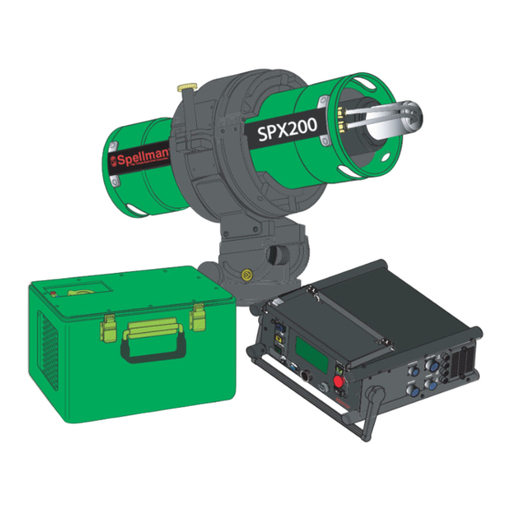
17. Cooling Unit Coolant Hose Fittings Buzzer 18. Cooling Unit Reservoir Cap Key Control 19. Cooling Power Connector 20. Nut Safety Figure 1-2 Control Unit Tube Head Assembly Cooling Unit Figure 1-3 Figure 1-4 Page 5 of 44 SPX Series System Manual 118173-001 Rev. D... -
Page 8: Manual Outline
SPX X-ray Controls and Indicators This section provides general information about the Chapter 4 details the controls and indicators on the SPX series units. Included in this section is a safety SPX Control Unit. Refer to this chapter during use for summary. -
Page 9: Safety Summary
Before operating or performing any maintenance on the SPX series, the user MUST have a thorough ! CAUTION ! understanding of x-ray machinery, generation, high An operating or maintenance voltage potential and x-ray control. -
Page 10: Radiation Hazard
These procedures must be strictly followed at all times. Page 8 of 44 SPX Series System Manual 118173-001 Rev. D... -
Page 11: Chapter 2
Tube head. Affix supporting blocks to the bottom of the carton. Make sure the legs are positioned to accommodate a pallet jack as shown in Figure 2-1. Page 9 of 44 SPX Series System Manual 118173-001 Rev. D... -
Page 12: Transporting The Unit
Figure 2-1 are in proper condition for Tube Head Shipping Container transportation according to the applicable regulations of the U.S. Department of Transportation.” Page 10 of 44 SPX Series System Manual 118173-001 Rev. D... -
Page 13: Equipment Checklists
(Dummy Plug) 305531-001 Assembly, Tube Head 3-000-3258-1 Air Cooled; 40° Cone Glass Insert Beryllium Window Assembly, Tube Head 3-000-3224-1 Liquid Cooled; 40° Cone Glass Insert Beryllium Window Page 11 of 44 SPX Series System Manual 118173-001 Rev. D... -
Page 14: Checklist - Optional Equipment
I.D. tag (Control Tag) providing the serial number, description, and part number. This data is used for identification, if warranty or service information is needed, and will be requested when contacting Spellman regarding Figure 2-3 the apparatus. Attached to the Control Unit and Tube head are warning labels. -
Page 15: Specifications - General System
Stabilization: kV and mA remain within 1% of set levels. Line voltage varied from 100- 130/200-250 VAC. Storage Temperature Range _ -65°F to 160°F (-54°C to 71°C) Figure 2-5 Page 13 of 44 SPX Series System Manual 118173-001 Rev. D... -
Page 16: Specifications - General Tube Head
Tube Head assemblies. Figure 2-6 and 2-7 illustrate the direction of the X-ray beam for both the 40° x 60° cone and the 360° panoramic models. Figure 2-7 Page 14 of 44 SPX Series System Manual 118173-001 Rev. D... -
Page 17: Specifications - Control Unit
Remains on during normal operation until X-ray is turned off. Safety Circuit Light: Illuminates after all interlock circuits are closed. If light is off the controller will not allow x-ray generation. Page 15 of 44 SPX Series System Manual 118173-001 Rev. D... -
Page 18: Specifications - Cooling Unit
Cooling Unit Connections: Self-sealing quick disconnects. Caution: Figure 2-9 Cooling unit shipped without coolant. Cooling unit must be filled to the appropriate level prior to connecting the system Page 16 of 44 SPX Series System Manual 118173-001 Rev. D... -
Page 19: Chapter 3
“Refilling the Tube Head” (see section 7-3). Check - Cooling Unit This check verifies the integrity of the Cooling Unit (liquid cooled Tube Heads only). Page 17 of 44 SPX Series System Manual 118173-001 Rev. D... -
Page 20: System Set Up Procedures
Tube Head base plate. 4. Install the line power cable: Connect the female end of the line power cable to the connector labeled “Power” on the Control Unit. Page 18 of 44 SPX Series System Manual 118173-001 Rev. D... -
Page 21: System Interconnections - Air Cooled
Connect the “jumper” (supplied) to the connector labeled “Interlock” on the do not employ Control Unit for units that an external interlock system. Page 19 of 44 SPX Series System Manual 118173-001 Rev. D... -
Page 22: External Interlock Connections
Pins “F” and “G” serve to confirm warning 24Vdc indicators are functional as a test for the operator. The signal can be configured high or low depending on the operator preference. Pin “G” supplies a +24V source. Page 20 of 44 SPX Series System Manual 118173-001 Rev. D... - Page 23 SPX X-ray Industrial Imaging System Figure 3-5 Page 21 of 44 SPX Series System Manual 118173-001 Rev. D...
- Page 24 SPX X-ray Industrial Imaging System Figure 3-6 Page 22 of 44 SPX Series System Manual 118173-001 Rev. D...
-
Page 25: Chapter 4
SPX X-ray Industrial Imaging System Chapter 4: Figure 4-1: SPX Front Panel Layout SPX Series Controls and Indicators The front panel is the primary user interface for the SPX system. It includes a key switch, two buttons, 3 indicators, a buzzer, a command dial, with a VFD display. -
Page 26: Spx Series Control Connections
Figure: 4-4 Power Cable Detail Cooling Hose (Liquid Cooled Units) – Provides coolant flow between the Cooler Unit and the Tube Head. Figures 4-15 and 4-16. Figure: 4-5 Power Input Cable Page 24 of 44 SPX Series System Manual 118173-001 Rev. D... - Page 27 Figure 4-9 Tube Head (160kV unit) 10 Pin Connector Controller End Tube Head Figure 4-11 Cooler Cable 8 Pin Connector Figure: 4-10 Tube Head Cooling Hose Controller End Cooler End Page 25 of 44 SPX Series System Manual 118173-001 Rev. D...
- Page 28 Figure 4-12 Interlock (Controller) PTO2A-16-8S Dummy Plug: Pins “A” and “B” connected for interlock closure. Figure: 4-15 Cooler Hose Couplings Figure: 4-14 Tube Head Cooler Hose Coupling Cooler Coupling Tube Head Page 26 of 44 SPX Series System Manual 118173-001 Rev. D...
- Page 29 SPX X-ray Industrial Imaging System Figure 4-16 SYSTEM INTERCONNECT DIAGRAM Note: Dummy plug connected if no external interlocks used Page 27 of 44 SPX Series System Manual 118173-001 Rev. D...
- Page 30 SPX X-ray Industrial Imaging System Figure 4-17 SYSTEM INTERCONNECT DIAGRAM Page 28 of 44 SPX Series System Manual 118173-001 Rev. D...
-
Page 31: Chapter 5
! WARNING! provided with this system has been pre-aged by the original manufacturer, and also tested and aged by Spellman. It is necessary, however, The operator of this X-ray unit, or that the voltage be run up to the required kV... - Page 32 SPX X-ray Industrial Imaging System Page 30 of 44 SPX Series System Manual 118173-001 Rev. D...
- Page 33 SPX X-ray Industrial Imaging System Page 31 of 44 SPX Series System Manual 118173-001 Rev. D...
-
Page 34: Chapter 6
Main Screen menu will start. Chapter 6: Depending on the system. 4. Insert the key into the Safety Key SPX Series System Operation lock, then turn it to the ON position, either the cooling fan or the coolant pump will energize to When the system is properly assembled, the cool the tube. -
Page 35: Fault Messages
OFF. the Over Voltage fault occurs repeatedly after During this time, heat generated at the restart, service is necessary. anode during operation is dissipated. Page 33 of 44 SPX Series System Manual 118173-001 Rev. D... -
Page 36: Gui Display
SPX X-ray Industrial Imaging System FAULT MESSAGES (Cont.) GUI Display Page 34 of 44 SPX Series System Manual 118173-001 Rev. D... -
Page 37: Fault Descriptions
Front Panel X-Ray On Lamp Not Working ARC Fault Power Supply or X-Ray-Tube ARC Occurred External Interlock Fault External Interlock Pins A & B not Jumped Light Confirm External Light Fault Page 35 of 44 SPX Series System Manual 118173-001 Rev. D... -
Page 38: Chapter 7
Introduction followed. Discrepancies discovered during these inspections must be noted and immediately The SPX Series Portable X-ray Unit is a reliable, corrected to avoid the possibility of equipment easily maintained, industrial x-ray device. With breakdown. The inspections described in these... -
Page 39: Care And Maintenance
3. Remove the top cover from the Control unit by first removing the bolts from the Page 37 of 44 SPX Series System Manual 118173-001 Rev. D... -
Page 40: Re-Pressurizing The Tube Head
(automobile tire NOTE... The pressure regulator type) on the back of the Tube Head. Use a supplied with the optional Spellman hose incorporated with a relief valve or recharge kit is factory set to 70 – 75 psi pressure regulator, and a gauge having an @ 70˚... -
Page 41: Legend - Tube Head Pressurization Set Up
Tube Head to achieve room temperature before attempting to re-pressurize. Temperature equilibrium eliminates errors resulting from differences between the gas supply and the Tube Head temperatures. Page 39 of 44 SPX Series System Manual 118173-001 Rev. D... -
Page 42: Re-Filling The Tube Head
5) Start the vacuum pump and allow it to run for at least 20 minutes for 160kV, (1 hour for 200kV and 300kV units). The final vacuum indicated on the regulator gauge should be at least 25” Hg. Page 40 of 44 SPX Series System Manual 118173-001 Rev. D... - Page 43 SPX X-ray Industrial Imaging System Page 41 of 44 SPX Series System Manual 118173-001 Rev. D...
- Page 44 25” Hg Connect New SF6 Cylinder Gas to Tube Head Start fill SF6 gas FINAL FILL NEW When gauge indicates 55 psi, Stop SF6 GAS this process Page 42 of 44 SPX Series System Manual 118173-001 Rev. D...
-
Page 45: Cooling Unit Upkeep
5. Turn the system OFF and remove the radiator cap. Inspect the coolant level and ensure it remained within 1/2" from the top of the reservoir. Add more coolant solution if necessary, and repeat step 4. Page 43 of 44 SPX Series System Manual 118173-001 Rev. D... -
Page 46: Cleaning - Coolant Filter
Unit to the Cooling Unit. Apply power, and allow coolant to circulate for three minutes. Re-check the coolant level to ensure it is 1/2" from the top. Add Cooling Solution as needed. Page 44 of 44 SPX Series System Manual 118173-001 Rev. D... - Page 47 CAUTION notes in the text indicate procedures to be followed to avoid possible damage to equipment. Copyright 2000, Spellman High Voltage Electronics Corporation. All Rights Reserved. This information contained in this publication is derived in part from proprietary and patent data. This information has...
- Page 48 WICHTIGE SICHERHEITSHINWEISE SICHERHEIT DIESES HOCHSPANNUNGSNETZTEIL ERZEUGT LEBENSGEFÄHRLICHE HOCHSPANNUNG. SEIN SIE SEHR VORSICHTIG BEI DER ARBEIT MIT DIESEM GERÄT. Das Hochspannungsnetzteil muß immer geerdet sein. Berühren Sie die Stecker des Netzteiles nur, wenn das Gerät ausgeschaltet ist und die elektrischen Kapazitäten des Netzteiles und der angeschlossenen Last entladen sind. Die internen Kapazitäten des Hochspannungsnetzteiles benötigen ca.
- Page 49 PRECAUTIONS IMPORTANTES POUR VOTRE SECURITE CONSIGNES DE SÉCURITÉ ETTE ALIMENTATION GÉNÈRE DES TENSIONS QUI SONT DANGEUREUSES ET PEUVENT ÊTRE FATALES OYEZ EXTRÊMENT VIGILANTS LORSQUE VOUS UTILISEZ CET ÉQUIPEMENT Les alimentations haute tension doivent toujours être mises à la masse. Ne touchez pas les connectiques sans que l’équipement soit éteint et que la capacité à la fois de la charge et de l’alimentation soient déchargées.
- Page 50 IMPORTANTI PRECAUZIONI DI SICUREZZA SICUREZZA QUESTO ALIMENTATORE GENERA TENSIONI CHE SONO PERICOLOSE E POTREBBERO ESSERE MORTALI. PONI ESTREMA CAUTELA QUANDO OPERI CON QUESO APPARECCHIO. Gli alimentatori ad alta tensione devono sempre essere collegati ad un impianto di terra. Non toccare le connessioni a meno che l’apparecchio sia stato spento e la capacità interna del carico e dell’alimentatore stesso siano scariche.
- Page 51 To obtain information on Spellman’s product warranty please visit our website at: http://www.spellmanhv.com/en/About/Warranty.aspx...
Need help?
Do you have a question about the SPX Series and is the answer not in the manual?
Questions and answers