
Subscribe to Our Youtube Channel
Related Manuals for CDVI ATRIUM ADH10


Summary of Contents for CDVI ATRIUM ADH10
- Page 1 ENGLISH ADH10 ATRIUM Schlage Integration Module The Installer’s Choice cdvigroup.com...
-
Page 2: Table Of Contents
6] WARRANTY - TERMS & CONDITIONS . . . . . . . . . . . . . . . . . . . . . . . . . . . . . . . . . . . . . . . . . . . . .22 Copyright (C) 2013 CDVI . All rights reserved . ADH10 is protected by copyright law and international treaties . Unauthorized reproduction or distribution of this product, or any portion of it, may result in severe civil and criminal penalties, and will be prosecuted to the maximum extent possible under law . -
Page 3: Product Presentation
ATRIUM - Schlage Integration Module (Control up to 10 Schlage Door Handles) 1] PRODUCT PRESENTATION One ATRIUM ADH10 controller has the capacity to control ten NDE, AD300 and/or AD400 SCHLAGE door handles. ATRIUM ver. 3.1 (or higher) multi-account software supports up to 100 door handles per account (site). This is accomplished by using ten ADH10 controllers connected to an IP network. -
Page 4: Notes And Recommendations
INSTALLATION MANUAL ADH10 ATRIUM - Schlage Integration Module (Control up to 10 Schlage Door Handles) 2] NOTES AND RECOMMENDATIONS Free Technical Support For technical support in U.S. or Canada, call 1-866-610-0102, Monday to Friday from 8:00 a.m. to 8:00 p.m. EST. For international technical support, please see the last page of this document or visit our website: www. cdvigroup.com. -
Page 5: Recommended Wiring
INSTALLATION MANUAL ADH10 ATRIUM - Schlage Integration Module (Control up to 10 Schlage Door Handles) Recommended Wiring Maximum Equipment Wire Type Size Length Ethernet CAT 5/5e 100m (300ft) RS485 bus Belden 9841, 9842 or equivalent 24AWG (0.51mm) 1220m (4000ft.) (Daisy Chain) (2 or 4 conductor shielded) * The Minimum Size Equipment Conductors for the AC mains required are 14 AWG if made of Copper or 12 AWG if made of Aluminium or Copper-Clad Aluminium. - Page 6 Battery Backup 12Vdc 7Ah rechargeable acid/lead or gel cell backup battery (UL/ULC: YUASA #NP7-12 Battery Capacity recommended, Europe: CDVI B7AH recommended). Ensure proper polarity. 250mA (default), 320mA, 500mA, or 1A. Refer to the user interface instruction manual for more Charging Current information on how to modify the battery charging current.
-
Page 7: Package Contents
INSTALLATION MANUAL ADH10 ATRIUM - Schlage Integration Module (Control up to 10 Schlage Door Handles) 3] PACKAGE CONTENTS This chapter details how to install and setup the 10-Door Handle Controller. What’s in the box: • One ADH10 controller • metal cabinet and connection diagram label • AC power cord • Metal cabinet accessory kit • Installation kit Wall Switch... -
Page 8: Location And Mounting
INSTALLATION MANUAL ADH10 ATRIUM - Schlage Integration Module (Control up to 10 Schlage Door Handles) Location and Mounting The cabinet is designed to be installed indoors, in a safe and secure location. Normal temperature and humidity levels should be maintained. Cabinet Dimensions: 40 cm (15.8”) high, 32 cm (12.6”) wide, 9 cm (3.54”) deep The Cabinet Can Accommodate: One 12Vdc @ 4.5AH or 7AH, gel cell type battery and wiring connections (15cm (6”) high, 6cm (2.5”) wide, 9 cm (3.54”) deep) Battery Model Voltage Capacity Length Width Height YUASA #NP7-12 12 Volt 7 Ah 151mm (5.94”) 65mm (2.56”) 97.5mm (3.84”) YUASA #NP4-12 12 Volt 4.5 Ah 90mm(3.54”) -
Page 9: Mounting Instructions
INSTALLATION MANUAL ADH10 ATRIUM - Schlage Integration Module (Control up to 10 Schlage Door Handles) 4] MOUNTING INSTRUCTIONS The box needs to be prepared before fixing it to its location. INSTALLING THE TAMPER SWITCHES Installing tamper switches allows the ADH10 to detect when the cabinet door is opened and/or when the cabinet is removed from the wall. If needed install the tamper switch(es) as follows: Metal box holes where to fix the wall tamper switch cdvigroup.com... - Page 10 INSTALLATION MANUAL ADH10 ATRIUM - Schlage Integration Module (Control up to 10 Schlage Door Handles) Install the wall tamper switch using the supplied bolts and nuts as shown in the following picture. Install the tamper switch plastic spacer on the back at bottom left side of Cabinet Side View the box as show in the following picture. Spacer Cabinet Door Spacer Screw Spacer cdvigroup.com...
- Page 11 INSTALLATION MANUAL ADH10 ATRIUM - Schlage Integration Module (Control up to 10 Schlage Door Handles) Install the door tamper switch by aligning the switch holes to the pre-installed plastic bracket pins. Press firmly to secure the tamper switch in position, then fix the bracket to is mounting flange. Fix the tamper switch to the bracket then mount the bracket on the mounting flange Bracket Door Tamper Switch Door Tamper Switch Mounting Flange cdvigroup.com...
-
Page 12: Installing The Box Lock
INSTALLATION MANUAL ADH10 ATRIUM - Schlage Integration Module (Control up to 10 Schlage Door Handles) Installing the box lock Installing the box lock allows to secure the box from non-authorized access. If needed install the box lock as shown in the picture (inside view of the door). Remove the box door knock-out. Insert the lock in the hole. Slide the “U” metal bracket into the lock groove as shown in the picture to secure the lock in place. Alternatively or complementary to the box lock, the box may be secured by fixing the cover to its base using screws. -
Page 13: Fixing The Box To Its Location
INSTALLATION MANUAL ADH10 ATRIUM - Schlage Integration Module (Control up to 10 Schlage Door Handles) Fixing the Box to its Location Install the box to its location using 4 screws (not supplied) as shown in the following picture. If the wall tamper switch is used, make sure that the tamper switch arm moves freely and is completely pushed in when the enclosure is installed on the wall. cdvigroup.com... -
Page 14: Installing The Adh10 Controller
INSTALLATION MANUAL ADH10 ATRIUM - Schlage Integration Module (Control up to 10 Schlage Door Handles) Installing the ADH10 Controller Install the 5 supplied PCB fasteners in the holes identified in red in the images below. cdvigroup.com... -
Page 15: Wiring Diagram
RDA- TDA- Once the connection is properly done as shown above, the ATRIUM ADH10 will automatically detect the Allegion GWE gateway, AD-300 or PIM400-485 on power on. The ADH10 can provide power to up to four GWE Gateways and/or PIM400-485. -
Page 16: Connecting The Box Tamper Switches
INSTALLATION MANUAL ADH10 ATRIUM - Schlage Integration Module (Control up to 10 Schlage Door Handles) Connecting the Box Tamper Switches Connecting the tamper switches allows the ADH10 Controller to detect when the cabinet door is opened and/or when the cabinet is removed from the wall. To install the tamper switches, see “Installing the Tamper Switches”. To use both switches: Connect one end of the supplied wire to the door tamper switch terminal and the other end to the wall tamper switch terminal. -
Page 17: Power Connections
INSTALLATION MANUAL ADH10 ATRIUM - Schlage Integration Module (Control up to 10 Schlage Door Handles) Power Connections Do not power up the ADH10 Controller until all connections are completed. The module operates from any 120/240 Vac sources using the supplied AC/DC power supply and provides fully monitored power solutions using: •... -
Page 18: Ac Terminal Fuse
INSTALLATION MANUAL ADH10 ATRIUM - Schlage Integration Module (Control up to 10 Schlage Door Handles) AC Terminal Fuse The following steps are only presented in case you need to replace the AC terminal fuse. 1. Disconnect the AC power cord from the power source or for permanent installation, turn off the power breaker 2. -
Page 19: Battery Backup
12Vdc 7Ah rechargeable acid/lead or gel cell backup battery (UL/ULC: YUASA #NP7-12 recommended, Europe: CDVI B7AH recommended). Ensure proper polarity. Various (means any type, from any manufacturer that complies with the “Technical Data and securement means” and meets the “Mark of conformity”... -
Page 20: Led Indicators
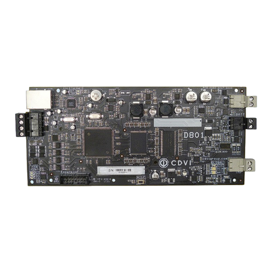
INSTALLATION MANUAL ADH10 ATRIUM - Schlage Integration Module (Control up to 10 Schlage Door Handles) LED Indicators The ADH10 Controller has several status LEDs that are very useful to diagnose problems when using or installing the system. Refer to the following image for the location of the LEDs on the PCB. All LEDs are explained in the following pages. -
Page 21: System Overview
ATRIUM - Schlage Integration Module (Control up to 10 Schlage Door Handles) System overview One ATRIUM ADH10 controller has the capacity to control ten AD300 and/or AD400 SCHLAGE door handles. ATRIUM ver. 3.1 (or higher) multi-account software supports up to 100 door handles per account (site). For increased flexibility, the system also supports proximity or magnetic stripe card readers. -
Page 22: Warranty - Terms & Conditions
CDVI or a local CDVI subsidiary. The “5 Year Warranty” is only applicable to hidden defects detected during the lifetime of the product, as defined by the CDVI Group (5 years or 200 000 operations - whichever of the two expires first). - Page 23 • Any product which has undergone even the slightest modification or change; • Any product which has been installed and/or used with any auxiliary device not supplied by CDVI; • Any product which has been used for demonstrations or display;...
- Page 24 Reference : Extranet : EXE-CDVI_IM ADH10 CMYK A4 EN 02 *G0301EN0412V01* CDVI Group FRANCE (Headquarter/Siège social) Phone: +33 (0)1 48 91 01 02 Fax: +33 (0)1 48 91 21 21 CDVI CDVI FRANCE + EXPORT IBÉRICA Phone: +33 (0)1 48 91 01 02...
Need help?
Do you have a question about the ATRIUM ADH10 and is the answer not in the manual?
Questions and answers