
Related Manuals for INIM Electronics F-COM


Summary of Contents for INIM Electronics F-COM
- Page 1 Installation and User manual EN 54-2 EN 54-4 EN 54-21 0051 0051-CPR-1754 F-COM Telephone communicator Installation and User manual DCMIINIEFCOM-100-20190716...
-
Page 2: Warranty
24 months. As INIM Electronics s.r.l. does not install this product directly, and due to the possibility that it may be used with other equipment not approved by Us;... -
Page 3: Table Of Contents
Installation and User manual Table of contents Warranty ........2 Limited warranty . - Page 4 Telephone communicator...
-
Page 5: Chapter 1 General Information
+39 0735 704912 e-mail: info@inim.biz Web: www.inim.biz The persons authorized by the manufacturer to repair or replace the parts of this system have authorization to work on INIM Electronics brand devices only. About this manual Manual code: DCMIINIEFCOM Revision: 1.00 Included documents •... -
Page 6: Chapter 2 Device Description
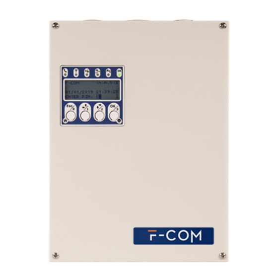
Telephone communicator Chapter 2 DEVICE DESCRIPTION The F-COM is a universal autonomous telephone communicator, certified in accordance with EN 54-21 and EN 54-4 standards. It is to be used with fire detection control panels manufactured both by Inim Electronics and other manufacturers. -
Page 7: Technical Description
Installation and User manual Technical description Table 1: Description of parts Signalling LEDs Power supply Display Mains power terminals Navigation buttons Ground connection point USB Port Battery terminals SIM card connector Thermal probe Antenna connector Cable entry hole RESET button to restart the communicator Frontplate anchor hole FACTORY button to restore factory settings Backplate anchor hole... - Page 8 Telephone communicator Table 2: Terminal board icon/identifier function Ground terminal 2, 3 L.E. Telephone line connection terminals 4, 5 L.I. Internal telephone line terminals Output terminal for confirmation of receipt of an alarm ALARM ACK communication Programmable output terminal (by default it activates in OUT1 the event of a connection fault) Output terminal that activates in the presence of...
-
Page 9: Ce Mark
Installation and User manual CE Mark Alarm transmission and fault warning routing equipment with embedded power supply equipment for use with fire detection and fire alarm systems installed in buildings Device description... -
Page 10: Chapter 3 Installation
Complete the connections with the terminals. Replace the frontplate. Connecting the switching power supply The F-COM must be powered via the 230V~ mains power supply, with necessary use of the two backup batteries. 3-2-1 Mains power 230V~ For the power supply from the network, it is necessary to provide a separate line deriving from the electrical distribution panel. - Page 11 Installation and User manual Connect the mains power supply to the terminals on the power-supply module ([A],table 1, K). For a safety standards compliant system, the Line must be connected to terminal “L” and the Neutral conductor to terminal “N”. The power supply must come directly from an electrical distribution panel via a reserved line.
-
Page 12: Mounting The Antenna
The lead batteries provide the secondary power source that will power the F-COM and the devices connected to its outputs when the primary power source is not present. -
Page 13: Connecting To A Pc
Installation and User manual Connecting to a PC It is necessary to connect to a PC equipped with the F-COM-STUDIO software for the programming, layout and monitoring of the system the F-COM is connected to. The connection with the PC can be achieved through a USB cable inserted into the appropriate connector on the main board (table 1, D). - Page 14 Telephone communicator F-COM F-COM SmartLine SmartLine ALARM FAULT CALL DIALER CALL ZONE 4 AUX R RELAY 3900Ohm 1500Ohm 100Ohm orange, brown, brown, black, white, red green, red brown For SmartLine control panels it is necessary to enable the “Output to fault warning routing equipment”...
- Page 15 Installation and User manual The outputs can be supervised. The “Interconnection fault” is activated in the event of: • open-collector output open, if the load to positive is not detected or when a short-circuit to ground is detected • open-collector output closed, in the event of an internal fault Table 4: Output functions terminal activation...
- Page 16 Telephone communicator INPUT INPUT Terminal IOx Terminal IOx supervised non supervised 3K9Ohm 100Ohm orange, brown, white, red black, brown When supervision is enabled, the occurrence of open and short-circuit conditions will generate an “Interconnection fault”. CONTACT Each "IOx" terminal has an internal resistor, a "pull-up" resistor, which allows to REFERENCE change the contact reference (to ground or positive) according to the programming.
- Page 17 Installation and User manual If none of the functions in the table are associated with an input, the activated actions will be those specified by events/actions programming (refer to Appendix PROGRAMMING • Polarity: OPTIONS Normally Open contact (default) Normally Closed contact •...
-
Page 18: Chapter 4 First Startup
On first startup of the communicator or restoring of factory data, the display provides the user with a fast programming guide. By following this guided procedure and configuring at least one telephone contact, thanks to the actions programmed at default (refer to Appendix A), the F-COM will be able to: •... - Page 19 Installation and User manual Table 6: Fast configuration of contacts Telephone number Preferential channel (PSTN or mobile) Contact ID Account code Supervision period IP address Port SIA-IP Account code Supervision period IP address Port IP2RX Account code Supervision period EN54 In order to guarantee compliance with the EN 54-21 standard, supervision must be enabled and the maximum period must be 24 hours.
-
Page 20: Using The Communicator
Chapter 5 USING THE COMMUNICATOR Users The F-COM communicator manages different access levels to the device, distinct from the system usability limitations. Each user must have an access PIN the first digit of which characterizes the typology and cannot be changed:... - Page 21 Installation and User manual Table 8: Signalling LEDs Icon description activation signal - Flashing green, indicates an ongoing communication on the GSM network, different from an alarm communication. - Flashing red, indicates an ongoing alarm communication on the GSM network. Indicates that the communicator is - Solid yellow, indicates a fault on the mobile Mobile net-...
-
Page 22: Language Used By The User Interface
Telephone communicator Table 11: Audible signalling from buzzer Tone description signal Reject 500Hz, 200ms Operation on user interface rejected “bop” Confirm 3kHz, 50ms Operation confirmed on user interface “beep” • It will activate upon activation of the ALARM CALL terminal. •... -
Page 23: Signals On The Display
Pressing OK when this symbol is selected deletes the last character entered. Signals on the display During normal operating conditions of the F-COM communicator, the LCD display shows the status of the communicator and any faults. Table 14: Signalling LEDs... -
Page 24: Main Menu
Telephone communicator Note When the display shows the field for PIN entry (4th line), the communicator buttons assume the enter-digit function (from 0 to 3). Main menu Once a valid access PIN has been entered, the display shows the main menu which varies according to the level of the user: Table 15: Main menu available for... -
Page 25: Appendix A Events
Installation and User manual Appendix A EVENTS The events managed by the communicator are listed in the table below. The “Events log” column indicates whether the event activation and event restored data is recorded in the events log. The “Activate Actions” column indicates whether the communicator can be programmed to trigger an action when the event occurs. - Page 26 Telephone communicator Activate Event Type Activates… Restores... Events log actions when the presence of the Telephone line when the presence of the Fault telephone line is no longer trouble telephone line is detected detected when the presence of a GMS SIM when the presence of a GMS SIM Error Fault...
- Page 27 Installation and User manual SIA-IP/ Contact Event Output Contacts Voice calls SMS text message IP2RX ID event event “Telephone line trouble” / activation/ Contacts #1 and Telephone line down None None “Restore telephone line LT / LR restore trouble” activation/ Contacts #1 and “SIM error”...
-
Page 28: Appendix B Simplified Declaration Of Conformity
F-COM 2014/53/ : www.inim.biz : Por la presente, INIM ELECTRONICS S.R.L. declara que el tipo de equipo radioeléctrico F-COM es conforme con la Directiva 2014/53/UE. El texto completo de la declaración UE de conformidad está disponible en la dirección Internet siguiente: www.inim.biz : INIM ELECTRONICS S.R.L. - Page 29 Direktyv 2014/53/ES. Visas ES atitikties deklaracijos tekstas prieinamas šiuo interneto adresu: www.inim.biz : Ar šo INIM ELECTRONICS S.R.L. deklar , ka radioiek rta F-COM atbilst Direkt vai 2014/53/ES. Pilns ES atbilst bas deklar cijas teksts ir pieejams š d interneta vietn : www.inim.biz...
- Page 30 Telephone communicator Simplified declaration of conformity...
-
Page 31: Weee
Installation and User manual WEEE Information on electrical and electronic device disposal (applicable in countries with recycling systems) The barred bin symbol found on the equipment or its box indicates that the product must be discarded separate from other waste at the end of its working life. - Page 32 Telephone communicator ISO 9001 Quality Management certified by BSI with certificate number FM530352 Via dei Lavoratori 10, Loc. Centobuchi 63076 Monteprandone (AP) ITALIA Tel. +39 0735 705007 _ Fax +39 0735 704912 info@inim.biz _ www.inim.biz...
Need help?
Do you have a question about the F-COM and is the answer not in the manual?
Questions and answers