Table of Contents
Advertisement
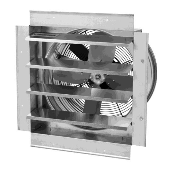
Exhaust Fan with Shutter
Owner's Manual
WARNING:
Read carefully and understand all ASSEMBLY AND OPERATION
INSTRUCTIONS before operating. Failure to follow the safety rules and other basic safety
precautions may result in serious personal injury.
Item # 52852, 52853, 52854
READ & SAVE THESE INSTRUCTIONS
Advertisement
Table of Contents

Related Manuals for Strongway 52852


Summary of Contents for Strongway 52852
- Page 1 Owner’s Manual WARNING: Read carefully and understand all ASSEMBLY AND OPERATION INSTRUCTIONS before operating. Failure to follow the safety rules and other basic safety precautions may result in serious personal injury. Item # 52852, 52853, 52854 READ & SAVE THESE INSTRUCTIONS...
- Page 2 Thank you very much for choosing a Strongway™ product! For future reference, please complete the owner’s record below: Serial Number/Lot Date Code: ________________________________ Purchase Date: ____________________________________________ Save the receipt, warranty, and this manual. It is important that you read the entire manual to become familiar with this product before you begin using it.
-
Page 3: Table Of Contents
Technical Specifications ........................4 Important Safety Information ....................... 4 Specific Operation Warnings ....................... 6 Installation ............................. 7 #52852, #52853, #52854 Wiring Diagram .................... 9 Before Each Use ............................ 9 Operating Instructions .......................... 9 Maintenance ............................9 #52852 & #52853 Parts Diagram ......................10 #52852 &... -
Page 4: Intended Use
Intended Use Strongway’s Exhaust Fan with Shutter is designed for exhaust and circulation of indoor air to the outdoors. Technical Specifications Item# Size Voltage Speeds Watts / Amps CFM / RPM 14″ 52852 230 Watt / 1.9 Amp 1400/1380 18″... - Page 5 ⚠WARNING WORK AREA SAFETY Inspect the work area before each use. Keep work area clean, dry, free of clutter, and well-lit. Cluttered, wet, or dark work areas can result in injury. Using the fan in confined work areas may put you dangerously close to cutting tools and rotating parts.
-
Page 6: Specific Operation Warnings
Disconnect the power from the fan and place the switch in the locked or off position before making any adjustments, changing accessories, or storing the fan. Such preventive safety measures reduce the risk of starting the fan accidentally. Surges in electrical power or excessive heat may cause the fan to turn off. -
Page 7: Installation
The unit has to be securely mounted in a rigid framework. See the following chart for the recommended wall hole sizes. Model # Size 16.9″ square 14″ 20.6″ 20.6″ 9.4″ 3.7″ 52852 16.2″ hole 18″ 24.1″ 24.1″ 10.2″ 3.7″ 20″ 52853 20.4″... - Page 8 hole 33.9″ square 30″ 37.6″ 37.6″ 3.7″ 52854 12.1″ 32.3″ hole 1. Use screws, nuts, and flat referrals to assemble the fan head to the shutter assembly and then firmly fasten the nuts and flat referrals to lock into place. Important: Use appropriate screws for framework and wall conditions.
-
Page 9: 52852, #52853, #52854 Wiring Diagram
Note: Be sure when the fan is mounted that the shutter louvers open upward and close downward. #52852, #52853, #52854 Wiring Diagram Before Each Use ⚠WARNING Be sure that both front and rear guard screws are completely tightened in locking position before operation. -
Page 10: 52852 & #52853 Parts Diagram
5. Allow the fan to completely dry before the next use. ⚠WARNING Disconnect power before servicing. Use OSHA approved lock-out tag-out devices on power supply to prevent shock and/or electrocution. #52852 & #52853 Parts Diagram #52852 & #52853 Parts List Part# Description Qty. Part# Description Qty. -
Page 11: 52854 Parts Diagram
Screw Motor Capacitor box Wind cabinet #52854 Parts Diagram #52854 Parts List Part# Description Qty. Part# Description Qty. Screw Cylinder Fan assembly Screw Motor Screw Fan assembly Capacitor box Wind cabinet Page 11 of 14... -
Page 12: Replacement Parts
Replacement Parts For replacement parts and technical questions, please call Customer Service at 1-800-222-5381. Not all product components are available for replacement. The illustrations provided are a convenient reference to the location and position of parts in the assembly sequence. ... -
Page 13: Limited Warranty
Northern Tool and Equipment Company, Inc. ("We'' or '"Us'') warrants to the original purchaser only ("You'' or “Your”) that the Strongway product purchased will be free from material defects in both materials and workmanship, normal wear and tear excepted, for a period of one year from date of purchase. - Page 14 Distributed by: Northern Tool & Equipment Company, Inc. Burnsville, Minnesota 55306 www.northerntool.com Made in China Page 14 of 14...
Need help?
Do you have a question about the 52852 and is the answer not in the manual?
Questions and answers