Table of Contents
Advertisement
Quick Links
Document #0023 Rev C
Whisper 500 Battery Charging Manual
Southwest Windpower, Inc.
Renewable Energy Made Simple
Owners Manual
Installation, Operation and Maintenance
For Battery Charging Applications
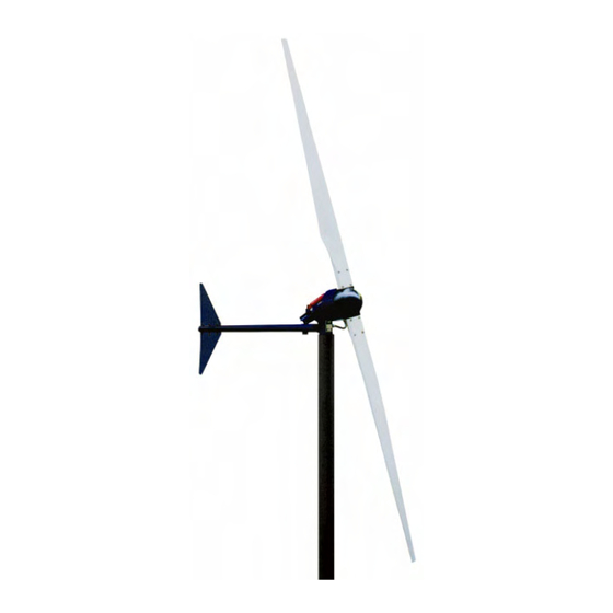
Whisper 500
Battery Charging
Wind Generator
Southwest Windpower, Inc.
1801 W Route 66
Flagstaff, Arizona 86001
Phone: (928)-779-9463
Fax: (928)-779-1485
Email: info@windenergy.com
Web page: http://www.windenergy.com
© 1 April 2006 Southwest Windpower , Inc
All Right Reserved
WIND GENERATOR SERIAL NUMBER ________________
SOUTHWEST WINDPOWER
April 2006
1
Advertisement
Table of Contents

Related Manuals for Southwest Windpower Whisper 500


Summary of Contents for Southwest Windpower Whisper 500
- Page 1 Wind Generator Southwest Windpower, Inc. 1801 W Route 66 Flagstaff, Arizona 86001 Phone: (928)-779-9463 Fax: (928)-779-1485 Email: info@windenergy.com Web page: http://www.windenergy.com © 1 April 2006 Southwest Windpower , Inc All Right Reserved WIND GENERATOR SERIAL NUMBER ________________ SOUTHWEST WINDPOWER April 2006...
- Page 2 Document #0023 Rev C Whisper 500 Battery Charging Manual BEFORE YOU BEGIN: Read this entire manual. Following the instructions and recommendations in this manual will help assure safe and enjoyable use of your new renewable energy system. SAFETY INFORMATION: These systems present mechanical, electrical and chemical (battery) hazards that can be life threatening.
-
Page 3: Table Of Contents
Document #0023 Rev C Whisper 500 Battery Charging Manual TABLE OF CONTENTS Section Page 1. Introduction 2. Controller and Diversion Load Installation 3. Wire Connections Controller to Battery Connections Controller to Wind Generator Wiring Brake Switch Diversion Load Wiring and Configuration Transformer 4. -
Page 4: Introduction
The Whisper 500 Wind Generator is designed to fit on a 5-inch schedule 40 steel pipe. The minimum recommended tower height is 7 meters (20 feet) above trees or obstacles within 100m (300ft). The lateral thrust load produced by the Whisper 500 at a wind speed of 45 m/s (100 mph) is 3.6 kN (800 lbs). - Page 5 Document #0023 Rev C Whisper 500 Battery Charging Manual Whisper 500 Battery Charging Schematic You will need to make the electrical connections as shown below. Whisper 500 Wind Generator Diversion Load Whisper Controller Transformer (HVLV only) Fuse External Brake Switch...
-
Page 6: Controller And Diversion Load Installation
Whisper 500 Controller and 4600 Diversion Load The Whisper 500 Controller MUST be mounted vertically on a wall as shown below. Even though the Whisper 500 Controller does not contain a diversion load, this mounting position is necessary to provide adequate cooling for the electronics and rectifier heat sink. -
Page 7: Wire Connections
Controller to Battery Connections Remove the Whisper Controller Electronic Cover and connect the battery and ground wires as shown in the accompanying figures. Caution: Southwest Windpower strongly recommends connecting the Controller to the batteries BEFORE making the wind turbine connections. -
Page 8: Controller To Wind Generator Wiring
Whisper 500 Battery Charging Manual Controller to Wind Generator Wiring Southwest Windpower strongly recommends connecting the controller to the batteries prior to connecting the wind generator to the controller. After connecting the controller to the batteries proceed by connecting the three wires from the wind generator to the controller as shown below. - Page 9 ▲ Distance (Meters) ** Note: The Whisper 500 High Voltage cannot be wired directly to the Whisper Controller. A step down voltage transformer is required to reduce the voltage to 24, 36 or 48 volts before connection to the Whisper Controller.
-
Page 10: Brake Switch
Document #0023 Rev C Whisper 500 Battery Charging Manual Install Brake Switch Mount the brake switch next to the Whisper Controller on 500LV applications or near the transformer with the 500HVLV. The brake switch should be connected in parallel with the three... -
Page 11: Diversion Load Wiring And Configuration
Red 1 Transformer ( High Voltage Only) Install transformer on heat resistant surface with adequate ventilation. The Whisper 500 voltage is “stepped” down to 24, 36 or 48 volts with utilizing the transformer. Refer to the chart on the following page for specific directions for configuring the transformer voltage. - Page 12 Whisper 500 Battery Charging Manual Transformer (Continued - High Voltage Only) Install transformer on heat resistant surface with adequate ventilation. The Whisper 500 voltage is “stepped” down to 24, 36 or 48 volts with utilizing the transformer. Refer to the chart below for spe- cific wiring directions for configuring the transformer voltage.
-
Page 13: Wind Generator Installation
Document #0023 Rev C Whisper 500 Battery Charging Manual 4. Wind Generator Installation Electrical Tests Complete these tests before mounting blades to rotor, and before installing turbine to top of tower. These tests confirm that the wind generator is functional and ready to install on the tower. -
Page 14: Install Tower Insert
Document #0023 Rev C Whisper 500 Battery Charging Manual Install Tower Insert on Yaw Shaft Part # Part Description IAC14A 5” tower insert IAR98 M10x55 Grade 10.9 zinc bolt IAR99 M10 zinc lockwasher IAR43 M8x30 SS set screw IAR17 M8 SS nylock hex nut... - Page 15 Document #0023 Rev C Whisper 500 Battery Charging Manual Connect Wires and Mount Wind Generator To Tower Mounting Instructions A) Use split bolts to make the electrical connec- tion between the yaw wires and the transmis- sion wires inside the tower. Any of the three yaw wires can go to any of the three transmis- sion wires.
- Page 16 Document #0023 Rev C Whisper 500 Battery Charging Manual Hardware Lay out the hardware contained in the Whisper 500 Hardware Kit and separate as appropriate. You will need metric sockets and wrenches to complete the installation. Item Part # Part Description...
-
Page 17: Install Tail Fin
Document #0023 Rev C Whisper 500 Battery Charging Manual Install Tail Fin and Strap Before installing the tail boom into the lower weldment, install the Tail fin and Tail strap as shown in the follow- ing pictures. The numbers with arrows refer to the item number in the table from Step 15. - Page 18 Document #0023 Rev C Whisper 500 Battery Charging Manual D) Note how one side of the tail strap has a hole and the other is a slot. Attach the side with the hole to the tail fin as show to the right. A stainless steel washer is used on the outside of the tail strap.
-
Page 19: Install Tail Boom
Document #0023 Rev C Whisper 500 Battery Charging Manual Install Tail Boom to Lower Weldment The numbers with arrows refer to the item number in the table from Step 15. Mounting Instructions Insert the tail boom into the lower weldment. Be sure the tail fins will be vertical when the tower is raised. -
Page 20: Install Blades And Nosecone
Document #0023 Rev C Whisper 500 Battery Charging Manual Install Blades, Blade Strap and Nosecone Blades as viewed from It is very important the blades are installed properly and upwind direction not backwards. When looking at the front of the tur- bine from an upwind position, the leading edge tape should be as shown in the picture to the right. - Page 21 IMPORTANT: Do not turn on the wind generator if the battery is not connected to the controller. Never operate the Whisper 500 without the battery properly connected to the Whisper Controller. IMPORTANT: The battery bank must have some charge on it for the wind generator to begin charging (ie do not connect a dead battery to the wind generator.
-
Page 22: Whisper Controller
Whisper 500 Battery Charging Manual Document #0023 Rev C 5. Whisper Controller Printed Circuit Board Introduction The Whisper Controller Printed Circuit Board is equipped with six switches that are used to set certain operating system parameters. The default switch settings are suitable for the majority of installations and should not be changed with the exception of two switches that MUST be changed to alter the system volt- age. - Page 23 It is not necessary to depress the Reset Switch after changing the switch setting. Note: Except in very special circumstances Southwest Windpower recommends Switch 3 remain in the “ON” position. Switch 4, Voltage Hysteresis, Default Setting “OFF”...
-
Page 24: Optional Equipment
Whisper 500 Battery Charging Manual Document #0023 Rev C Optional Equipment Display (Liquid Crystal Display - LCD Display Installation The optional LCD display may be mounted either on the Whisper Controller base unit, or in a standard 4” wall type switch receptacle. Mounting hardware is provided with the display. An ethernet CAT5 cable is provided to mount the display on the Controller base. - Page 25 Whisper 500 Battery Charging Manual Document #0023 Rev C Anemometer Connection The Whisper Controller has been designed to accommodate a Model #40 anemometer, manufactured by NRG. Other equivalent anemometers may work, compare manufacturers specifications. A terminal block on the circuit board is the connection point for the two anemometer signal wires. The terminal block connections are labeled +/- and the polarity should be observed since some anemometers require spe- cific polarity connections.
-
Page 26: Controller Operation
The diversion switch is located on the top of the controller to the left of the LEDs. Setting the switch to “OFF” causes the power produced by the generator to be diverted the Diversion Load. The Diversion Load is located with the controller enclosure for Whisper 100 and 200’s. Whisper 500’ s have an external Diversion Load. Note: •... - Page 27 Whisper 500 Battery Charging Manual Document #0023 Rev C LED Operation Steady illumination of the Green LED indicates that batteries are being charged by the wind generator. Steady illumination of the Red LED indicates that all available power produced by the wind generator is being diverted to the Diversion Load as a result of operator request.
- Page 28 Whisper 500 Battery Charging Manual Document #0023 Rev C LCD Display Operation Operational Overview The LCD Display adds a tremendous set of features to your wind generator system. Controller measure- ments can be monitored and operational parameters can be adjusted. Take the time to learn about your Whisper Controller Display to take advantage of its many features.
- Page 29 Whisper 500 Battery Charging Manual Document #0023 Rev C Main Page (1) When first connected, the Display begins with the Main Page. The Main Page displays all of the Controller’s measured parameters, including battery charging status, windspeed, charging voltage, battery charge cur- rent, and turbine power.
- Page 30 Whisper 500 Battery Charging Manual Document #0023 Rev C Display Menu Functions Page Display Menu Effect Select Main On or Off 00.0 mph “A” go to A ring 11.3V 00.0A 000W ”B” go to B ring A Ring Energy 0000 000.00...
- Page 31 Whisper 500 Battery Charging Manual Document #0023 Rev C Reset Reset “B” “B” “B” “B” Energy History “A” “A” “A” Main Display “B” “B” “B” Mode Regulation “A” “A” “A” “A” Charge On/Off “A” Regulation Regulation “B” “B” “B” “B”...
-
Page 32: Maintenance
Whisper 500 Battery Charging Manual Document #0023 Rev C 6. MAINTENANCE Monthly Maintenance 1. TEST BRAKE (This checks electrical wiring.) STOP THE WIND GENERATOR IN A MODERATE WIND (CHARGING BUT NOT FURLING) No unusual difficulty or noise should be experienced in Brake switch stopping the propeller. - Page 33 Whisper 500 Battery Charging Manual Document #0023 Rev C Annual Maintenance 1. CHECK THE BATTERY Check with battery manufacturer for care and maintenance Add only distilled water if low. Tighten battery connections Remove corrosion and protect terminals Wipe tops with baking soda solution.
- Page 34 Whisper 500 Battery Charging Manual Document #0023 Rev C Date Problem/Observation Action Taken SOUTHWEST WINDPOWER April 2006...
-
Page 35: Troubleshooting
If the wind generator starts, the problem is in the Whisper Propeller does not turn = Mechanical Problem Controller and contact Southwest Windpower. If the See Table: Symptoms of Mechanical Problems wind generator still does not start the problem is in the tower wiring or the wind generator. - Page 36 Whisper 500 Battery Charging Manual Document #0023 Rev C TABLE: SYMPTOMS OF MECHANICAL PROBLEMS Symptom Possible Cause Correction 1. Propeller is stationary, even in a. Ice in generator, or uneven ice on i. Wait for warm weather high winds propeller i.
- Page 37 Whisper 500 Battery Charging Manual Document #0023 Rev C TABLE: SYMPTOMS OF ELECTRICAL PROBLEMS Symptom Possible Cause Correction i. Turn WIND switch ON 1. Propeller turns slowly even in a. WIND switch is OFF (brake on) i. Charge batteries with external strong wind, but will not start b.
-
Page 38: Mechanical Repairs And Parts Replacement
Whisper 500 Battery Charging Manual Document #0023 Rev C Mechanical Repairs and Parts Replacement CHANGING THE SYSTEM BATTERY VOLTAGE You must complete all of the steps below to change the system voltage 1. Change the wind generator connection voltage (see figures below) 2. - Page 39 Whisper 500 Battery Charging Manual Document #0023 Rev C BRUSHES AND BRUSH HOLDERS Disconnect the wiring harness in the wiring box, disconnect cord grip nuts and remove the lower frame cord grip body. Remove the four screws retaining the brush card and pull the card and attached wiring harness away from its opening.
- Page 40 Whisper 500 Battery Charging Manual Document #0023 Rev C Balancing Blades 1. Set round side of blade on knife edge with leading edge parallel to table. Mark the balance point precisely. Balance point 2. Weigh each blade separately (use a grocery store scale) and mark weight on each blade.
- Page 41 Whisper 500 Battery Charging Manual Document #0023 Rev C Exploded View Parts List-Whisper 500 Use item # and description when ordering. Item Description Quantity Rotor Spindle Stator Yaw Housing Yaw Shaft Brush Card Assembly Brush Card Plate Wire Box and Gasket Spacer Hex Head Screw M8x40 CL10.9...
- Page 42 Whisper 500 Battery Charging Manual Document #0023 Rev C SOUTHWEST WINDPOWER April 2006...
Need help?
Do you have a question about the Whisper 500 and is the answer not in the manual?
Questions and answers