Table of Contents
Advertisement
Advertisement
Table of Contents

Related Manuals for Shini SPV-U Series

Summary of Contents for Shini SPV-U Series
- Page 1 SPV-U Proportional Valve Date: Sep, 2018 Version: Ver.C...
-
Page 3: Table Of Contents
Content General Description ..................5 1.1 Coding Principle ..................6 1.2 Feature ....................6 1.3 Technical Specifications ................8 1.3.1 External Dimension ............... 8 1.3.2 Specifications ................8 1.4 Safety Regulations .................. 9 1.4.1 Safety Signs and Labels ............... 9 1.5 Exemption Clause ................... - Page 4 6.2.2 Check after Installation ............... 19 Drawing and Parts List ................20 7.1 Assembly Drawing ................20 7.2 Parts List ....................21 Electrical Diagram ..................22 Table Index Table 2-1:Specifications ................... 8 Table 5-1:Working with SAL-U(-E)、SAL-UG parameter Settings ....12 Picture Index Picture 2-1:Proportional valve ................
-
Page 5: General Description
Read this manual carefully before operation to prevent damage of the machine or personal injuries. SPV-U series proportional valve mix regrind and new materials in a proper proportion, and then send them back to the molding machine to achieve a proportional mixing and loading effect. -
Page 6: Coding Principle
SPV - xxU - C Equipped with Control Box First two codes: Pipe Diameter (mm) U: European type Shini Proportional Valves 1.2 Feature 1) Standard configuration ● European type design, classy appearance, easy installation and operation. ● Unique design of valve body, make material conveying more smoothly. - Page 7 Chapter 6, which contains service instructions intended for service engineers. Other chapters contain instructions for the daily operator. Any modifications of the machine must be approved by SHINI in order to avoid personal injury and damage to machine. We shall not be liable for any damage caused by unauthorized change of the machine.
-
Page 8: Technical Specifications
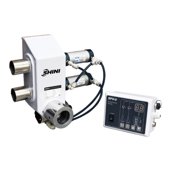
1.3 Technical Specifications 1.3.1 External Dimension Picture 1-1:Proportional valve Picture 1-2:Control box 1.3.2 Specifications Table 1-1:Specifications Compressed Air Driven Maximum Pipe Size Dimensions (mm) Model Ver. Weight (kg) Pressure Means Material Flow (inch) H×W×D 3kgf/cm SPV-38U-(C) Cylinders 350kg/hr 270 × 260 × 150 Compressed Air 3kgf/cm SPV-50U-(C) -
Page 9: Safety Regulations
Shini (including employees and agents). Shini is exempted from liability for any costs, fees, claims and losses caused by reasons below: 1. Any careless or man-made installations, operation and maintenances upon machines without referring to the manual prior to machine using. -
Page 10: Structure Characteristics And Working Principle
Structure Characteristics and Working Principle 2.1 Working Principle After set the material loading time and regrind material’s proportion, the cylinder drives the conical diaphragm valve 1 and conical diaphragm valve 2’s opening and closing time to control the proportional new material and regrind material entered in the hopper which to reach the purpose of proportional mixing. -
Page 11: Installation And Debugging
Installation and Debugging Read the instruction carefully before installation, must observe the installation steps as follows! When installing SPV, please connect to the compressed air tube according to the requirements. Notes for Installation and Positioning: 1) Machine just can be mounted in vertical position. Make sure there’s no pipe, fixed structure or other objects above the installing location and around the machine which may block machine’s installation, hit objects or injure human person. -
Page 12: Application And Operation
Application and Operation SAL-U(-E) or SAL-UG has integrated with the SPV-U single-layer control function. When SPV-U collocated with hopper loader SAL-U(-E) or SAL-UG, if users just need single-layer control mode, please according to the SAL-U(-E), SAL-UG operation manual to set the loading time; if users need double, three, four layers control mode, it should use SPV-U original control box to set the parameter. -
Page 13: Instruction Diagram About Connecting With Sal-Ug
4.1.3 Instruction Diagram about Connecting with SAL-UG Picture 4-2:Instruction diagram about connecting with SAL-UG 4.2 SPV-U with Independent Control Box 4.2.1 About the Control Panel Picture 4-3:About the control panel Name Function Description Power Power on to start the machine Loading time set Press this key to set loading time Regrind percentage set... -
Page 14: Start / Stop
4.2.2 Start / Stop 1. Power on to start the machine, it will display software version "XX" (about 1second). 2. Turn off the power to stop the machine. 3. Shut off the loading signal to stop mixing. 4.2.3 Settings Parameter Setting 1. - Page 15 Picture 4-4:Material loading diagram of hopper (single-layer working mode) 2. Working mode 2: (1-percentage)×half of the loading time is for new material + percentage × half of the loading time is for regrind material + (1-percentage) × half of the loading time is for new material + percentage × half of the loading time is for regrind material.
-
Page 16: Picture 5-5:Material Loading Diagram Of Hopper (Double-Layer Working Mode) 15 Picture 5-6:Material Loading Diagram Of Hopper (Three-Layer Working Mode)
Picture 4-6:Material loading diagram of hopper (three-layer working mode) 4. Working mode 4: (1-percentage) × one fourth of the Loading time is for new material + percentage × one fourth loading time is for regrind material + (1-percentage) × one fourth of the Loading time is for new material + percentage ×... -
Page 17: Connections
※At setting mode, if to adjust 【F01~F03】 , the software will automatically ensure regrind loading time be no less than 1sec 4.2.4 Connections Picture 4-8:Connections Name Function Description SPV-U will be receiving an activation Input loading signal signal when hopper loader starts SPV-U will be receiving an activation Power cable signal when hopper loader starts... -
Page 18: Maintenance And Repair
Maintenance and Repair 6.1 Maintenance All the repair work should be done by professionals in order to prevent personal injuries and damage of the machine. Keep the external valve body clean, pay attention to the solenoid valve's maintenance. 18(24) -
Page 19: Maintenance Schedule
6.2 Maintenance Schedule 6.2.1 About the Machine Model Manufacture date Voltage Ф Frequency Power 6.2.2 Check after Installation Make sure the pipe connecting is correct Make sure the connecting pipe is lock and tighten Make sure the mounting base is lock and tighten Electrical Installation Voltage check: Signal wire connecting... -
Page 20: Drawing And Parts List
Drawing and Parts List 7.1 Assembly Drawing Remarks: Please refer to material List 15.2 for specific explanation of the arabic numbers in parts drawing. 20(24) -
Page 21: Parts List
7.2 Parts List Part No. Name SPV-38U-(C) SPV-50U-(C) O sealing ring* YR20375300000 YR20503500000 Set screw M6×10 YW68061000000 YW68006600000 Set screw M4×5 YW68004500000 YW68004500000 Pipe sleeve for absorbing material BH13003800010 BH13005000010 Cross socket head cap screw M4×25 YW63042500000 YW63042500000 Solenoid valve* YE32421600000 YE32421600000 Feed-in pipe... -
Page 22: Electrical Diagram
Electrical Diagram 22(24) - Page 23 23(24)
- Page 24 24(24)
Need help?
Do you have a question about the SPV-U Series and is the answer not in the manual?
Questions and answers