Advertisement
Save these instructions for future use!
FAILURE TO READ AND FOLLOW ALL INSTRUCTIONS
CAREFULLY BEFORE INSTALLING OR OPERATING THIS
CONTROL COULD CAUSE PERSONAL INJURY AND/OR
PROPERTY DAMAGE.
APPLICATIONS
THERMOSTAT APPLICATION GUIDE
Description
Modulating PWM output, gas furnace
Heat Pump (with Aux. or Emergency Heat), 2 Stage
Systems with up to 3 Stages Heat, 2 Stages Cool
Heat Only Systems
Wired Remote Temperature Sensor (Indoor or Outdoor)
Dual Fuel Feature (Heat Pump Mode)
Compressor Fault Detection
Humidifi cation Control
Dehumidifi cation Control
Please refer to the system installation and operating
manual for more detailed instructions and options.
SPECIFICATIONS
Electrical Rating:
Battery Power . . . . . . . . . . . . . . . . . . . . . . . . . . mV to 30 VAC, NEC Class II, 50/60 Hz or DC
Input-Hardwire . . . . . . . . . . . . . . . . . . . . . . . . . 20 to 30 VAC
Terminal Load . . . . . . . . . . . . . . . . . . . . . . . . . . . . . 1.5A per terminal, 2.5A maximum all terminals combined
Setpoint Range . . . . . . . . . . . . . . . . . . . . . . . . . . . . 45 to 99°F (7 to 32°C)
Differential (Single Stage) . . . . . . . . . . . . . . . . . . . . Heat 0.6°F; Cool 1.2°F
Differential (Multi-Stage) . . . . . . . . . . . . . . . . . . . . . Heat 0.6°F; Cool 1.2°F
Differential (Heat Pump) . . . . . . . . . . . . . . . . . . . . . Heat 1.2°F; Cool 1.5°F
Operating Ambient. . . . . . . . . . . . . . . . . . . . . . . . . . 32°F to +105°F (0 to +41°C)
Operating Humidity . . . . . . . . . . . . . . . . . . . . . . . . . 90% non-condensing max.
Shipping Temperature Range . . . . . . . . . . . . . . . . . -4 to +150°F (-20 to +65°C)
Dimensions Thermostat. . . . . . . . . . . . . . . . . . . . . . 4.6"H x 5.9"W x 1.2"D
CAUTION
!
To prevent electrical shock and/or equipment damage,
disconnect electric power to system at main fuse or circuit
breaker box until installation is complete.
Index
Installation and Operating Instructions
for Hum/Dehum Modulating
Touchscreen Thermostat
Model
(-)HC-TST412MDMS
Modulating Touchscreen Thermostat
Yes
Yes
Yes
Yes
Yes
Yes
Yes
Yes
Yes
ATTENTION: MERCURY NOTICE
This product does not contain mercury. However, this
product may replace a product that contains mercury.
Mercury and products containing mercury must not be
discarded in household trash. Do not touch any spilled
mercury. Wearing non-absorbent gloves, clean up any
Page
spilled mercury and place in a sealed container. For prop-
2
er disposal of a product containing mercury or a sealed
2
container of spilled mercury, place it in a suitable shipping
container. Refer to www.white-rodgers.com for location
3
to send product containing mercury.
5
6
10
12
15
Programming Choices
7 Day
5/1/1 Day
Non-Programmable
(-)HC-TST412MDMS
PART NO. 37-6981A
0843
Advertisement

Related Manuals for protech HC-TST412MDMS Series

Summary of Contents for protech HC-TST412MDMS Series
-
Page 1: Table Of Contents
Installation and Operating Instructions for Hum/Dehum Modulating Touchscreen Thermostat Save these instructions for future use! FAILURE TO READ AND FOLLOW ALL INSTRUCTIONS Model Programming Choices CAREFULLY BEFORE INSTALLING OR OPERATING THIS CONTROL COULD CAUSE PERSONAL INJURY AND/OR (-)HC-TST412MDMS 7 Day 5/1/1 Day Non-Programmable PROPERTY DAMAGE. -
Page 2: Installation
INSTALLATION Battery Location WARNING 2 "AA" alkaline batteries are included in the thermostat at the factory with a battery tag to prevent power drainage. Remove Thermostat installation and all components of the the battery tag to engage the batteries. control system shall conform to Class II circuits per To replace batteries, set system to OFF, remove thermostat the NEC code. -
Page 3: Wiring Diagrams
WIRING DIAGRAM Modulating Touchscreen Thermostat Wiring Diagrams (-)HC-TST412MDMS Single Stage, Multi-Stage, Heat Pump Figure 2 – Typical Dual Fuel Application - Single Stage Heat Pump THERMOSTAT MODEL: (-)HC-TST412MDMS REMOTE SENSOR: F145-1378 (OUTDOOR), F145-1328 (INDOOR) PLENUM SENSOR: 47-21711-20 Figure 3 – Two Stage THERMOSTAT MODEL: (-)HC-TST412MDMS REMOTE SENSOR: F145-1378 (OUTDOOR), F145-1328 (INDOOR) PLENUM SENSOR: 47-21711-20... - Page 4 WIRING DIAGRAM Figure 5 – Two Stage THERMOSTAT MODEL: (-)HC-TST412MDMS REMOTE SENSOR: F145-1378 (OUTDOOR), F145-1328 (INDOOR) Figure 6 – Typical Wiring for 120V Humidifi er System Relay 90-290Q or equivalent 24 VAC 120 VAC NEUTRAL TRANSFORMER Humidifier 120 VAC NEUTRAL System (Refer to furnace instructions for humidity information) Figure 7 –...
-
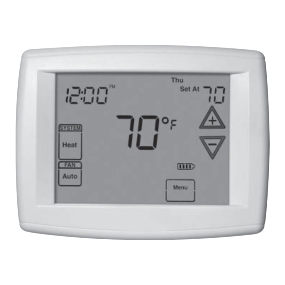
Page 5: Thermostat Quick Reference
THERMOSTAT QUICK REFERENCE Home Screen Description Figure 9 – Home Screen Display Room Temperature Day of Week Set Temperature Time of Day Temperature UP/Down used for System modifying set point Switch as well as to navigating the menus Enters comfort Switch temperature settings into the schedule... -
Page 6: Installer Confi Guration Menu
INSTALLER/CONFIGURATION MENU To enter the menu: Press the Menu touch key. Press and hold for 5 seconds the Installer Confi g touch key. When the key is released the display will show menu item #1 in the table below. Press to advance to the next menu item or to return to a previous menu item. - Page 7 INSTALLER/CONFIGURATION MENU AO (80) 79-35 Selects Auxiliary Heat cut out temperature. This item appears if HP1 or HP2 is selected and outdoor sensor is installed and enabled. Hd (OFF) Selects Humidity Display alternate with time. Humidity -20-20 Selects Humidity Display adjustment. H1, OD Hr (OFF) LO, HI...
- Page 8 INSTALLER/CONFIGURATION MENU accurately calibrated at the factory, however you have the will fl ash if an attempt is made to adjust the temperature option to change the display temperature value to match beyond the range selected. your previous thermostat, if you so prefer. 22.
- Page 9 INSTALLER/CONFIGURATION MENU pressing the keys to set desired humidity (range desire by using touch keys. Then, only the indoor remote temperature reading will be used for 40% to 95%) level followed by pressing Humidity key control. again. This dehumidifi cation feature uses less energy by maintaining temperature and dehumidifying only when a 26.
-
Page 10: Operating Your Thermostat
OPERATING YOUR THERMOSTAT Check Thermostat Operation 3. Adjust temperature setting to 3° above room temperature. Any additional stages of auxiliary heat should begin to operate NOTE and the display will show "System On +2". 4. Press to adjust the thermostat below room temperature. To prevent static discharge problems, touch side of The heating system should stop operating. - Page 11 OPERATING YOUR THERMOSTAT IMPORTANT! Special Test Mode for PWM (V) output 3. FAN On Prog. – Programmable Fan (Installer function only) FAN On Prog indicates that a time period has FAN Prog selected in the Set Schedule mode (see Programmable The PWM (V) output controls the modulating gas valve.
-
Page 12: Programming
PROGRAMMING Enter the Cooling Program Automatic Daylight Saving Calculation 1. Press the SYSTEM button until the Cool icon appears. The Real Time Clock will adjust automatically for daylight sav- ings time in the following manner: 2. Follow Enter Heating Program instructions for entering cooling times and temperatures. - Page 13 PROGRAMMING Energy Saving Factory Pre-Program The (-)HC-TST412MDMS thermostats are programmed with the energy saving settings shown in the table below for all days of the week. If this program suits your needs, simply set the thermostat clock and press the RUN button. The table below shows the factory set heating and cooling schedule for all days of the week.
- Page 14 PROGRAMMING Wired Remote Temperature Sensing The example shows that the weight selected would prioritize One remote temperature sensor can be installed indoor or the overall averaged temperature between the two sensors. outdoor and connected to the thermostat by a maximum The high weight selection caused the remote sensor to have cable length of 100 meters (300 feet).
-
Page 15: Troubleshooting
TROUBLESHOOTING Reset Operation Note: When thermostat is reset, installer confi guration menu settings and programming will reset to factory settings. If a voltage spike or static discharge blanks out the display or causes erratic thermostat operation, you can reset the thermostat by removing the wires from terminals R and C (do not short them together) and removing batteries for 2 minutes. - Page 16 HOMEOWNER HELP LINE: 1-800-284-2925...
Need help?
Do you have a question about the HC-TST412MDMS Series and is the answer not in the manual?
Questions and answers