Table of Contents
Advertisement
Quick Links
Advertisement
Table of Contents

Subscribe to Our Youtube Channel
Related Manuals for Delta-T SM150T


Summary of Contents for Delta-T SM150T
- Page 1 User Manual for the SM150T Soil Moisture Sensor Delta-T Devices Ltd...
- Page 2 Notices Copyright All parts of the SM150T design and documentation are the exclusive right of Delta-T Devices and covered under copyright law. Copyright © 2016 Delta-T Devices Ltd. Patents The SM150T is protected under international law by the following patents:-...
-
Page 3: Table Of Contents
Contents Introduction Description Features Dimensions Parts list Care and Safety How the SM150T works Operation Cable Connections Installation HH150 Meter HH2 Meter Logger connections and configuration GP1 Logger GP2 Logger Controller DL6 Logger DL2e Logger Other Data Loggers Logger Grounding... - Page 4 Appendix 2: The SM150 Temperature Sensor Global warming and climate studies Civil engineering Soil contamination and hydrogeology Agriculture SM150T Temperature Measurement Effect of Temperature on Water Permittivity Resistance to Temperature Lookup Table Technical Support Index Introduction SM150T User Manual 1.0...
-
Page 5: Introduction
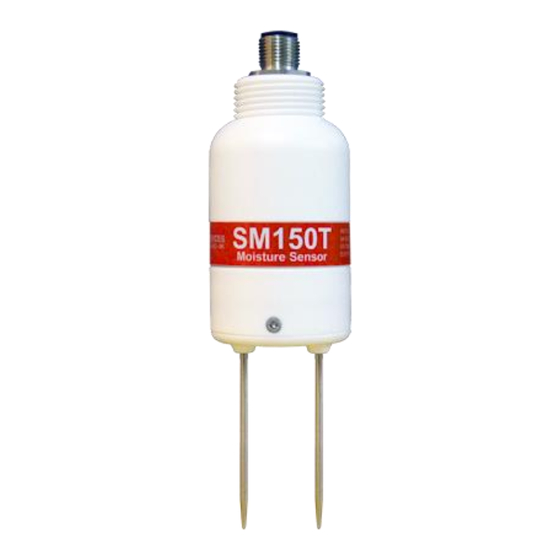
Introduction Description The SM150T measures soil moisture content and temperature. Its sealed plastic body is attached to two sensing rods which insert directly into the soil for taking readings. A waterproof plug connects to a choice of signal cables. Both extension cables and extension tubes can be used. -
Page 6: Dimensions
Dimensions Cable connector sealed to IP68 M12, 5 pin, male Thread ¾inch BSP for connecting to Extension Tube(s) 22mm 40 mm Introduction SM150T User Manual 1.0... -
Page 7: Parts List
Parts list Your shipment may include the following: SM150T soil moisture sensor HH150 +SM150T Kit HH150 includes 1m cable, Connects to SM150T SMCS/d-HH2 0.9m cable Connects SM150 to HH2 SMSC/lw-05 5m cable 200mm flying leads Connect to data logger Logger extension cables... -
Page 8: Care And Safety
Do not pull the SM150T out of the soil by its cable. If you feel strong resistance when inserting the SM150T into soil, it is likely you have encountered a stone. Stop pushing and re-insert at a new location. -
Page 9: How The Sm150T Works
4 and air 1) The permittivity of the soil has a strong influence on the applied field… …which is detected by the SM150T, resulting in a stable voltage output that… Soil Moisture ...acts as a simple, sensitive measure of... -
Page 10: Operation
Extension cables* can be joined up to a recommended maximum of 100m (for GP1 or GP2 data loggers) – see Specifications on page 33. *Note: for full accuracy, do not use extension cables with the HH150 ** Note The HH150 meter does not record temperature. Operation SM150T User Manual 1.0... -
Page 11: Installation
Note: The SM150T is not suitable for soil surface temperature measurements. For soil temperature near the surface dig a trench and install horizontally as shown below. Cover both SM150T and the first 30cm of cable with at least 5cm of soil. Installing at depth ... -
Page 12: Hh150 Meter
HH150 Meter Connect the SM150T to the HH150 meter. With the meter OFF, press the right Off – menu button. This wakes and allows you to set the meter to display readings - as % volumetric water content of either Mineral, Peat Mix, Coir, Mineral Wool or Perlite soils, or to show the sensor output in Volts. -
Page 13: Hh2 Meter
Esc to discard the reading. 20.3 %vol Remove the SM150T from the soil and move to a new location... If you have saved data, connect your HH2 to a PC and run HH2Read to retrieve the readings. -
Page 14: Logger Connections And Configuration
Using the DeltaLINK2 logger software, configure channel 1 or 2 as soil moisture sensor type SM150T channel 3 or 4 as SM150T Temperature. Two more SM150T sensors can be added, to Temp3 and/or Temp4 channels to measure soil moisture -if temperature readings are not required... -
Page 15: Gp2 Logger Controller
Fit wire link For configuration details see the DeltaLINK software sensor Info Panel and Help or the GP2 User Manual. Configure each soil moisture channel as sensor type SM150T and configure the temperature channel as sensor type SM150T Temperature. Operation ... -
Page 16: Dl6 Logger
DL6 Logger 6 SM150Ts can be connected to a DL6. Each soil moisture sensor is wired as a differential, powered sensor. A DL6 logger can only read one SM150T temperature sensor. These details illustrate connection to channels 6 & 7 SM150T... -
Page 17: Dl2E Logger
See also the DL2e User Manual and the Ls2Win online help You need a PC running Ls2Win version 1.0 SR10 or later. A free upgrade can be obtained from www.delta-t.co.uk or from the Software and manuals DVD. Operation SM150T User Manual 1.0... -
Page 18: Other Data Loggers
10 K thermistor, ±0.5⁰C over 0-40°C grey (Thermistor (5.8kΩ to 28kΩ - See Resistance Lookup connection) table) Low noise 0v (sensor 0v) Cable shield green (Can use power 0V if sensor 0V not (Noise shield) available) Operation SM150T User Manual 1.0... - Page 19 Polynomial conversion below (or on page 28) or Linearisation table conversion on page 29 Note: Output signals in the range 0 to 1.0 volts from the SM150T, corresponding to ~0 to 60% water content in mineral soils – see Linearisation table conversion on page 29.
- Page 20 1) Convert Volts V to using the following equation = 1 + 14.4396 V − 31.2587V + 49.0575V − 36.5575V + 10.7117V Where V is the SM150T soil moisture output converted from milliVolts to Volts. √ ε θ θ = ( √ ε − a...
-
Page 21: Logger Grounding
M12 connector of the SM150T. In addition, if used in an electrically noisy environment - such as a farm or greenhouse - then the presence of a ground loop can permit AC signals to inject noise and so disrupt readings. - Page 22 M12 connector on the SM150T. Figure 2 This diagrams shows that if the logger is not well grounded then a potential ground loop can exist between the sensor and the power supply and/or mains power.
- Page 23 Figure 4 This diagram shows a battery or high quality power supply with no leakage current to ground. The logger is grounded. The potential ground loop between logger and sensor is mitigated by the differential wiring of the SM150T. This is the best arrangement.
-
Page 24: Calibration
Delta-T loggers and moisture meters. This section explains how these calibrations work, how to adapt them for other soils and how to provide calibrations for other data loggers. -
Page 25: Soil Calibration
[ref 4.]. For a particular soil, the contribution from the soil particles can be assumed to be constant, so the refractive index measured by the SM150T is only affected by changes to the water content, . This relationship simplifies to: ... - Page 26 Appendix 1 on page 42. Soil specific calibration can significantly improve the accuracy of individual readings - but make less of an improvement to readings where installation and sampling errors are high. Operation SM150T User Manual 1.0...
-
Page 27: Sensor Calibration
This response can be approximated either by a polynomial (below) or by a linearisation table (see next page): Polynomial (for use over the full range of SM150T readings) √ �� = 1.0 + 14.4396�� − 31.2587�� + 49.0575�� − 36.5575��... -
Page 28: Soil Moisture Reading
Linearisation table (for use over the full range of SM150T readings) 0.000 1.000 0.300 3.576 0.600 5.101 0.900 6.778 1.200 8.924 0.075 1.942 0.375 3.964 0.675 5.503 0.975 7.232 1.275 9.743 0.150 2.620 0.450 4.337 0.750... - Page 29 Linearisation table conversion The conversion from SM150T reading (Volts) to soil moisture or %vol) can be accomplished by a look-up table. The following table lists the values used for the DL2e data logger: Mineral Organic Mineral Organic Soil Soil...
-
Page 30: Troubleshooting
Troubleshooting Always try to identify which part of the measurement system is the source of the difficulty. For the SM150T this may fall into one of the following areas: The measurement device What equipment is being used to read the probe output? ... - Page 31 With the pins half-immersed in tap water an HH2 set to read an SM150T with soil type set to Organic should give a reading in the range 80 to 100%vol. Troubleshooting ...
- Page 32 % vol (mineral) 20.00% moisture values %vol (organic) below 70%vol 10.00% 0.00% Conductivity EC (mS.m Graph: showing the effect of salinity on SM150T sensor output when fully immersed in water with no soil present. Troubleshooting SM150T User Manual 1.0...
-
Page 33: Technical Reference
See page 24. 7 See Appendix 2 on page 49. 8 Note: The DL6 has only one temperature channel. The DL6 error contribution to SM150T temperature measurement is negligible compared to the accuracy of the SM150T temperature sensor itself. The two only become comparable below -15C. - Page 34 Conductivity response This chart shows how salinity affects the output of the soil moisture sensor at various soil moisture levels. SM150T conductivity response at different water contents 100% (water) ~60% ~45% ~38% ~30% ~20% Conductivity EC (mS.m non- slightly moderately...
- Page 35 Temperature response of soil moisture readings The effect of temperature on the SM150T soil moisture readings in any particular soil will depend on a combination of effects: The SM150T soil moisture electronics has very low temperature sensitivity, and makes a negligible contribution to the overall sensitivity.
- Page 36 Sampling Volume The SM150T is most sensitive to signals very close to the two rods, but a small proportion of the signal reaches up to 50mm from the rods. SM150T field of sensitivity surrounding the rods 0.08 0.07 0.06 0.05 0.04...
- Page 37 If the SM150T is inserted too close to the wall of a plant pot the sensing field can “see” outside the pot. This behaviour is shown in the graph below. SM150T Error close to wall of plant pot. live pin nearest to pot wall...
- Page 38 Electromagnetic Compatibility (EMC) General information SM150T is a Class A product, intended for operation in non-residential environments. Only use cables and accessories authorised by Delta-T (sensor cables from other sources for example may adversely affect product performance and affect quality of results).
-
Page 39: Definitions
To convert from volumetric to gravimetric water content, use the equation where is the density of water (= 1g.cm is the bulk density of the sample ( Technical Reference SM150T User Manual 1.0... - Page 40 = 0.01 mS.cm = 10 µS.cm Soil salinity can be classified using the following descriptive categories: non- slightly moderately strongly extremely saline saline saline saline saline 1000 1200 1400 1600 mS.m dS.m Classification of salinity Technical Reference SM150T User Manual 1.0...
-
Page 41: References
Water Resour. Res., 28, 2345-2352 Or, D. and J.M. Wraith 1999 Temperature effects on soil bulk dielectric permittivity measured by time domain reflectometry: A physical model. Water Resour Res., 35, 371-383 References SM150T User Manual 1.0... -
Page 42: Appendix 1
Underlying principle Soil moisture content () is proportional to the refractive index of the soil () as measured by the SM150T (see Calibration section). The goal of calibration is to generate two coefficients (a ) which can be used in a linear equation to convert probe readings into soil moisture: ... -
Page 43: Laboratory Calibration For Non-Clay Soils
Measure the volume occupied by the sample. = 463.5ml Weigh the sample, including the beaker. = 743.3g Appendix 1 SM150T User Manual 1.0... - Page 44 Insert SM150T into the sample and record its output in Volts. = 0.350V Dry the sample thoroughly. With mineral soils this is usually achieved by keeping it in the oven at 105°C for several hours or days (the time required depends on the sample size and porosity).
- Page 45 = 1.66 = 8.51 In this example this soil is now calibrated. You can now use these two numbers in place of the standard mineral or organic calibration factors to convert SM150T readings into volumetric water content θ using: ...
-
Page 46: Laboratory Calibration For Clay Soils
Laboratory calibration for clay soils This technique is adapted to avoid the near-impossibility of inserting the SM150T into completely dry clay soil. It requires taking measurements at 2 significantly different, but still damp, moisture levels. Equipment you will need: ... - Page 47 Insert SM150T into the wet sample and record its output in Volts. = 0.349V Dry the sample until still moist, ~15% water content. Gentle warming can be used to accelerate the process, but take care not to over-dry in places, and allow time for the water content to equilibrate throughout the sample before taking a reading.
- Page 48 = 9.00 = 1.58 In this example this soil is now calibrated. You can now use these two numbers in place of the standard mineral or organic calibration factors to convert SM150T readings into volumetric water content θ using: ...
-
Page 49: Appendix 2
Temperature may be measured alongside soil water content for studies of evapotranspiration, soil water balance and irrigation. Soil strength and seedling emergence depend on soil moisture and temperature, and both need to be taken into account when deciding when to sow. Appendix 2: SM150T User Manual 1.0... -
Page 50: Sm150T Temperature Measurement
SM150T Temperature Measurement The SM150T Temperature sensor uses a thermistor with a 10K resistance at 25 ˚C. However: A. This sensor has a different response curve from the more widely used 10K3A1B type. The response curve is given in the Resistance to Temperature Lookup Table on page 53 B. - Page 51 50. Otherwise, correct the resistance reading before applying the response curve. You need to know the resistance of the Power 0V wire in the SM150T cable (Rc) and establish whether your logger uses voltage or current excitation for resistance measurement.
-
Page 52: Effect Of Temperature On Water Permittivity
R = a0 + a1 * Rmeas Where: a0 = – Ic.Rc.Rref / Vref a1 = 1 – Ic.Rc / Vref Ic = 18 mA (SM150T sensor supply current) For Delta-T EXT/5W-xx series cables: Rc = 0.066 Ω.m-1 For the SMSC/lw-05 5m logger cable Rc = 0.33 Ω... -
Page 53: Resistance To Temperature Lookup Table
Note: This table has been optimised for use as a look-up table. To minimise linear interpolation errors the data points fall either side of the manufacturers’ specified sensor response curve. This helps optimise the overall accuracy of readings. Appendix 2: SM150T User Manual 1.0... -
Page 54: Technical Support
Delta-T shall be under no liability in respect of any defect arising from fair wear and tear, and the warranty does not cover damage through misuse or inexpert servicing, or other circumstances beyond their control. - Page 55 No goods or equipment should be returned to Delta-T without first obtaining the return authorisation from Delta-T or our distributor. On receipt of the goods at Delta-T you will be given a reference number. Always refer to this reference number in any subsequent correspondence. The goods will be inspected and you will be informed of the likely cost and delay.
-
Page 56: Index
GP1, 14, 16, 30 volts to %vol, 19, 29 other, 18 Logger Grounding, 21 Definitions, 39 Description, 5 Dielectric performance, 27 Moisture content, 5, 9, 41, 42 refractive index, 24, 25, 42 Dimensions, 6 Index SM150T User Manual 1.0... - Page 57 25, 26, 39, 42, 43, 46 Technical Support Tel: +44 1638 742922 Delta-T Devices Ltd Fax: +44 1638 743155 130 Low Road E-mail: tech.support@delta-t.co.uk Burwell sales@delta-t.co.uk Cambridge CB25 0EJ Web: www.delta-t.co.uk England (UK) Index SM150T User Manual 1.0...
Need help?
Do you have a question about the SM150T and is the answer not in the manual?
Questions and answers