Table of Contents
Advertisement
Advertisement
Table of Contents

Related Manuals for Allot SG-9500 Series


Summary of Contents for Allot SG-9500 Series
- Page 1 Service Gateway SG-9500 Hardware Guide...
- Page 3 Operation of this equipment in a residential area is likely to cause harmful interference in which case the user will be required to correct the interference at his own expense. Changes or modifications not expressly approved by Allot Communication Ltd. could void the user's authority to operate the equipment.
-
Page 4: Version History
Document updates are released in electronic form from time to time and the most up to date version of this document will always be found on Allot’s online Knowledge Base. To check for more recent versions, login to the support area www.allot.com/support.html... -
Page 5: Table Of Contents
CHAPTER 5: PREPARATION AND INSTALLATION ........5-1 Unpacking the SG-9500 ......................5-1 Mounting the SG-9500 ....................... 5-2 Space and Airflow Requirements ..................... 5-2 Rack Mounting the Service Gateway ..................5-2 DC Power Source........................5-5 CHAPTER 6: DEPLOYING THE SG-9500 ............6-1 Allot SG-9500 Hardware Guide... - Page 6 Environmental Specifications ....................8-2 Safety Certifications ........................8-2 Laser Safety Requirements ......................8-3 Laser Classification........................8-3 Laser Information ........................8-3 Laser Safety Statutory Warning ....................8-3 Training for Laser Safety ......................8-3 Laser Device Operating Precautions ..................8-3 viii Allot SG-9500 Hardware Guide...
- Page 7 Figure 3-3: HD 24 Fiber Bypass Unit ..................3-5 Figure 3-4: Fan out Fiber Optic cable (Single Mode) ..............3-5 Figure 3-5: Allot USB Bypass Cable ..................3-7 Figure 4-1: IEC-320 C13 to C14 Power Cord ................4-2 Figure 5-1: AC Power Cable Anchors ..................5-4 Figure 6-1: Connecting to Network Traffic ..................
- Page 8 Figure 7-1: Battery Removal ......................7-3 Allot SG-9500 Hardware Guide...
-
Page 9: Chapter 1: Introducing The Sg-9500
Its small-footprint is equipped with the same rich features and functions as our chassis- based Allot Service Gateway, enabling you to roll out Security as a Service as well as other revenue-generating services rapidly and cost-effectively, while you lower your total cost of ownership and accelerate ROI. -
Page 10: Planning Your Deployment
2 SFP+ Optical Transceivers (either SR Fiber or LR Fiber) for Management Ports NOTE All Transceivers MUST be provided by Allot specifically for the SG-9500. Any other Transceivers will not function in the SG- 9500. BYPASS USB Control Cable(s) – number depends on number of... -
Page 11: Cabling And Transceivers
- Standard 9/125 SM Standard OM4 B.I (must be ordered 62/125 (must be separately, SG- ordered separately, CABLE-40G-10G- SG-CABLE-40G- SPLIT-SM). 10G-SPLIT-MM). MTP to 4 x Full MTP to 4 x Full Duplex LC Duplex LC Allot SG-9500 Hardware Guide... -
Page 12: Transceivers
Transceivers NOTE All Transceivers MUST be provided by Allot specifically for the SG-9500. Any other Transceivers will not function in the SG- 9500. The following transceivers (available from Allot) may be used with the SG-9500: 10G Fiber SG-TRNSCV-10G-SR ... -
Page 13: Figure 1-1 - Full Duplex Lc Connector
Single Mode fiber (SM) dual LC Connectors. The 24-port Fiber Bypass unit uses MTP Fiber connectors. The 8-port Copper Bypass Unit uses dual RJ45 connectors. Figure 1-1 – Full Duplex LC Connector NOTE Color and appearance of actual connectors may vary. Allot SG-9500 Hardware Guide... -
Page 15: Chapter 2: Connectors And Leds
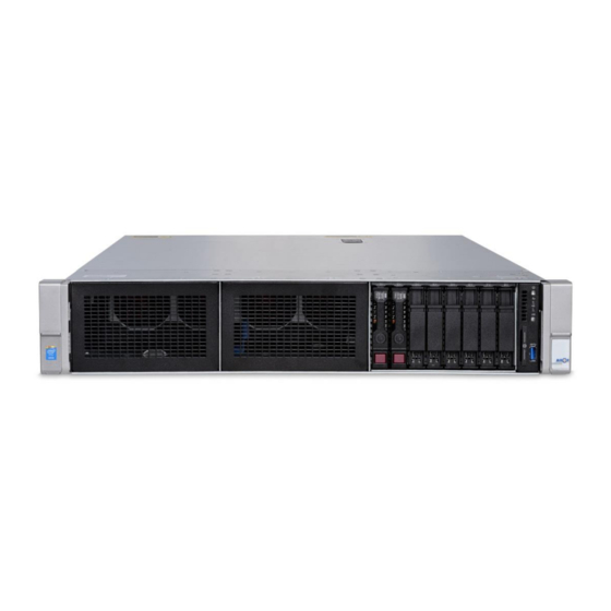
Chapter 2: Connectors and LEDs Allot Service Gateway 9500 (SG-9500) provides a high performance service delivery platform with rich functionality in an efficient, small-footprint appliance. With high- density 10 Gigabit Ethernet connectivity and 140 Gbps of throughput, the platform allows enterprises, cloud data centers and ISP networks to satisfy the ever-growing demand for Internet bandwidth and network-based services in cost-efficient manner. -
Page 16: Front Panel Buttons And Leds Description
1 Hz/cycle per sec = Remote management or firmware upgrade in progress • 4 Hz/cycle per sec = iLo manual reboot sequence initiated • 8 Hz/cycle per sec = iLo manual reboot sequence in progress Off = Deactivated Allot SG-9500 Hardware Guide... -
Page 17: Front Panel Connectors
Px.Ly where 'x' stands for the PCIe slot number and 'y' stands for the port number within that PCIe slot. For example, the second port on the third PCIe card (S3) will be identified as P3.L2. Allot SG-9500 Hardware Guide... -
Page 18: Power Supply
CAUTION The USB connectors should ONLY be connected to one or two Allot Bypass Units. The bypass cable should only be connected/disconnected when the system is powered down. Power Supply The SG-9500 contains two built in power supply modules and a dual line feed for Redundancy purposes. -
Page 19: Figure 2-6 - Sg-9500 Ac Power Feed
Chapter 2: Connectors and LEDs Figure 2-6 – SG-9500 AC Power Feed Figure 2-7 – SG-9500 DC Power Feed Allot SG-9500 Hardware Guide... -
Page 20: Figure 2-8 - Sg-9500 Dc Pem With Grounding Screw
Chapter 2: Connectors and LEDs Grounding Screw Figure 2-8 – SG-9500 DC PEM with Grounding Screw Allot SG-9500 Hardware Guide... -
Page 21: Chapter 3: Bypass
"connectivity insurance" in the event of a subsystems failure. Each Allot Bypass unit features low insertion loss (< 1dB) in both Normal mode and Bypass mode and fast switching time (< 10mSec) between modes. A Service Gateway unit Network ports must be connected to the appropriate External Bypass Unit. -
Page 22: Hd 8 Fiber Or Copper Bypass Unit
Chapter 3: Bypass HD 8 Fiber or Copper Bypass Unit The HD 8 Bypass Unit (previously known as the Allot Multi-Port Bypass) can work in conjunction with all SG-9500 Configuration and is available with Fiber or Copper interfaces. Links 1-4 to... -
Page 23: Hd 16 Fiber Bypass Unit
In addition, the HD 16 Fiber Bypass Unit includes two D-type 9-pin connectors (DB-9) for connection to the SG-9500 via special DB-9/USB cables (available from Allot). The HD 16 Fiber Bypass Unit is a passive optical device with no need for external power connection. - Page 24 Duplex LC connector on the Bypass unit’s front panel the Tx connector is the left LC connector and the Rx is the right LC connector. Primary connects to the USB port on the SG-9500 Secondary is not in use. Allot SG-9500 Hardware Guide...
-
Page 25: Hd 24 Fiber Bypass Unit
A single HD 24 Fiber Bypass unit supports up to 24 ports (12 links). For more links additional units are required. In addition, the HD 24 Fiber Bypass Unit includes two D-type 9-pin connectors (DB-9) for connection to the SG-9500 via special DB-9/USB cables (available from Allot) Allot SG-9500 Hardware Guide... - Page 26 MTP connectors are used with Fan-out patch cables which each handle 2 10G links (4 10G ports total). These cables are supplied with the bypass unit. Primary connects to a USB port on the SG-9500 Secondary is not used at this time. Allot SG-9500 Hardware Guide...
-
Page 27: External Bypass Control Cabling
Single USB Unit Cable (1:1) connected to the Primary port on the Bypass Unit and one of the two USB ports on the rear of the SG-9500. WARNING To avoid damage, use ONLY the cable provided with the Bypass Unit for connection to the SG-9500. Figure 3-5: Allot USB Bypass Cable Allot SG-9500 Hardware Guide... -
Page 29: Chapter 4: Power Connectivity Planning
DC and AC Cabling Requirements and Overcurrent Protection ATTENTION Allot does NOT provide DC cables. Power Source Requirements Installation of this equipment must comply with local and regional electrical regulations governing the installation of information technology equipment by licensed electricians. -
Page 30: Electrical Grounding Requirements
Because of the high ground-leakage currents associated with multiple servers connected to the same power source, Allot recommends the use of a PDU that is either permanently wired to the building’s branch circuit or includes a non detachable cord that is wired to an industrial-style plug. -
Page 31: Dc Cable Specifications
Connector unit end - The connectors that plug into the AC receptacle on the unit must be an approved IEC 320, C13 type female connector. DC Cable Specifications Allot does not provide DC power cables. WARNING OVER CURRENT PROTECTION FOR THE SYSTEM MUST BE PROVIDED AT THE INSTALLATION SITE FOR EACH SUPPLY CIRCUIT. - Page 32 The cord must have local safety approvals, and preferable additional approvals such as UL, CSA, TUV or VDE. For a cord set assembly, the cords must be protected against physical damage and arranged in appropriate cable ducts. Allot SG-9500 Hardware Guide...
-
Page 33: Chapter 5: Preparation And Installation
Remove all items from the box. If any items listed on the purchase order are missing, notify Allot customer service immediately. Inspect the product for damage. If there is damage, notify Allot customer service immediately. Save the box and packing material for possible future shipment. -
Page 34: Mounting The Sg-9500
The leveling jacks are extended to the floor. The full weight of the rack rests on the leveling jacks. The stabilizing feet are attached to the rack if it is a single-rack installation. The racks are coupled together in multiple-rack installations. Allot SG-9500 Hardware Guide... - Page 35 Chapter 5: Preparation and Installation Only one component is extended at a time. A rack may become unstable if more than one component is extended for any reason. AVERTISSEMENT Pour limiter les risques de blessure ou de détérioration du matériel, vérifiez les points suivants : Les pieds de mise à...
-
Page 36: Figure 5-1: Ac Power Cable Anchors
Plug the power cord into a grounded (earthed) electrical outlet that is easily accessible at all times. Unplug the power cord from the power supply to disconnect power to the equipment. Allot SG-9500 Hardware Guide... -
Page 37: Dc Power Source
Chapter 5: Preparation and Installation Do not route the power cord where it can be walked on or pinched by items placed against it. Pay particular attention to the plug, electrical outlet, and the point where the cord extends from the server. AVERTISSEMENT Pour limiter les risques d'électrocution ou de détérioration du matériel : Ne désactivez pas la prise de terre du cordon d'alimentation. - Page 38 (0.138 in); the diameter of a screw type terminal must be 4.0 mm (0.157 in). Stack each same-colored pair of wires and then attach them to the same power source. The power cord consists of three wires (black, red, and green). Allot SG-9500 Hardware Guide...
-
Page 39: Chapter 6: Deploying The Sg-9500
See Chapter 3: Bypass on page 3-1 for details concerning connecting HD 8, HD 16 and HD 24 Bypass units to the SG-9500 and the network. CAUTION The bypass cable should only be connected/disconnected when the system is powered down. Allot SG-9500 Hardware Guide... -
Page 40: Powering Up The Sg-9500
During the initial boot it is possible to modify the server configuration ROM default settings, press the F9 key in the POST screen to enter the UEFI System Utilities screen. By default, the System Utilities menus are in the English language. Allot SG-9500 Hardware Guide... -
Page 41: Initial Configuration
Chapter 6: Deploying the SG-9500 Initial Configuration The iLO System The iLO system is a standard component of the SG-9500 that simplifies initial server setup, server health monitoring, power and thermal optimization, and remote server administration. The iLO subsystem includes an intelligent microprocessor, secure memory, and a dedicated network interface. -
Page 42: Figure 6-2: Connecting Ilo To A Dedicated Switch
Chapter 6: Deploying the SG-9500 Connecting iLO to the Network It is recommended to connect the iLO ports on each SG-9500 to the network through a dedicated switch. Figure 6-2: Connecting iLO to a Dedicated Switch Allot SG-9500 Hardware Guide... -
Page 43: Figure 6-3: Initial Screen
Chapter 6: Deploying the SG-9500 Setting the IP for the iLO Connect a keyboard, mouse and display to the SG-9500 to set the iLo's IP address via the BIOS/UEFI. Power up the SG-9500 When the initial screen appears press F9 to open “System Utilities”. -
Page 44: Figure 6-4: System Utilities Screen
Chapter 6: Deploying the SG-9500 Figure 6-4: System Utilities Screen The System Configuration Screen opens. On the System Configuration screen select “Network Options” Figure 6-5: System Configuration Screen Allot SG-9500 Hardware Guide... -
Page 45: Figure 6-6: Network Options Screen
Chapter 6: Deploying the SG-9500 NOTE It is possible to change the default user name and password for the iLO by selected User Management on the System Configuration screen, selecting Edit/Remove User > Action and entering the desired values when prompted. Define your iLO parameters such as IP address and Subnet Mask Figure 6-6: Network Options Screen Press F10 to save your settings... -
Page 46: Figure 6-7: Ilo Login Information
> Action and entering the desired values when prompted. Enter the IP address for the ILO into a web browser (Internet Explorer or Edge recommended). NOTE If you are using Safari or Chrome you must use the Java based option. Allot SG-9500 Hardware Guide... -
Page 47: Figure 6-8: Ilo Login Screen
Chapter 6: Deploying the SG-9500 Enter the iLO User Name and Password and click Log In. Figure 6-8: iLO Login Screen The ILO Overview Screen opens. Select Remote Console from the list of options on the left of the screen. Figure 6-9: iLO Overview Screen... -
Page 48: Figure 6-10: Ilo Remote Console Screen
Figure 6-10: iLO Remote Console Screen NOTE It is also possible to download the iLO Mobile App from this page, for use on Apple and Android based mobile devices. 6-10 Allot SG-9500 Hardware Guide... -
Page 49: Figure 6-11: Ilo Remote Console
Chapter 6: Deploying the SG-9500 The Remote Console opens where you can log in to the Allot CLI for device configuration. Figure 6-11: iLO Remote Console Configuring the SG-9500 After entering the Remote Console, enter sysadmin for the login and sysadmin for the password. - Page 50 Reboot the SG-9500 by entering the following command: ac_reboot After the SG-9500 has rebooted, configure the 1G Copper ports as auto/auto using the following command: go config nic <nic's label>:auto:auto For example, go config nic P1.L1:auto:auto 6-12 Allot SG-9500 Hardware Guide...
- Page 51 IP. The IP is moved to the selected ports. Changing the AOS Passwords Allot provides end-users with CLI access to the system via a user privilege called “sysadmin”. The sysadmin user can access all of the CLI commands outlined in...
- Page 52 NetXplorer Operator wishes to add a new In-line Platform to the NetXplorer the admin password of that In-line Platform must be entered. In addition, no policy changes can be saved without the correct admin password. The default admin password is allot. NOTE Allot STRONGLY recommends that the default passwords are changed to ensure a minimum level of security.
-
Page 53: Chapter 7: Maintenance
System Cooling Fans System RTC Battery For information concerning how to replace any element in the SG-9500, contact Allot Customer Support at support@allot.com. Power Modules Two pluggable redundant Power Supplies are located at the rear bottom side of the SG- 9500. -
Page 54: System Rtc Battery
Replace only with the spare designated for this product. • To remove the battery: Power down the server. Remove all power: Disconnect each power cord from the power source. Disconnect each power cord from the server. Allot SG-9500 Hardware Guide... - Page 55 Chapter 7: Maintenance Remove the server from the rack Remove the top access panel Remove the secondary PCIe riser cage Locate the battery Remove the battery. Figure 7-1: Battery Removal To replace the battery, reverse the removal procedure.
-
Page 57: Chapter 8: Technical Information
EMC CERTIFICATIONS 55022:2010/AC:2011, EN 55032:2012/AC:2013, EN 55024: 2010, EN 61000-3-2:2014 & EN 6100-3- 3:2008 FCC CFR 47 Part 15 Subpart B, Industry Canada ICES-003, Issue 5 VCCI Technical Requirements, V-3/2013.04: Member no.: 1798 (C3775, R-3404, G-620, T1630) Allot SG-9500 Hardware Guide... -
Page 58: Environmental Specifications
9144 m (30,000 ft) altitude Safety Certifications FCC Rating Class A Normative CISPR 22; EN55022; EN55024; FCC CFR 47, Pt 15; ICES- 003; CNS13438; Standards GB9254; K22;K24; EN 61000-3-2; EN 61000- 3-3; EN 60950-1; IEC 60950-1 Allot SG-9500 Hardware Guide... -
Page 59: Laser Safety Requirements
As long as the Equipment is operated in accordance with the applicable safety instructions, the Hazard Level in Equipment access locations is inherently Class 1. Allot provides product and installation information in order that the products may be installed and serviced safely. - Page 60 ópticos cuando no haya ningún cable de fibra conectado. Evite la exposición y no mire fijamente a las aberturas. Varning: Osynlig laserstrålning kan spridas från öppningen på optiska portar om ingen fiberoptikkabel är ansluten. Undvik exponering och stirra inte in i öppningarna. Allot SG-9500 Hardware Guide...
- Page 61 Allot SG-9500 Hardware Guide...
Need help?
Do you have a question about the SG-9500 Series and is the answer not in the manual?
Questions and answers