Table of Contents
Advertisement
OPEratING MaNual
for flow meters of the product line:
"VSI High Definition Flow Meter"
Grey cast iron version
Stainless steel version
VSE Volumentechnik GmbH
Hönnestraße 49
58809 Neuenrade / Germany
Phone
+ 49 (0)23 94 /616 30
Fax
+ 49 (0)23 94 /616 33
E-Mail
info@vse-flow.com
Internet www.vse-flow.com
1
Advertisement
Chapters
Table of Contents

Related Manuals for vse VSI 0.04

Summary of Contents for vse VSI 0.04
- Page 1 OPEratING MaNual for flow meters of the product line: “VSI High Definition Flow Meter“ Grey cast iron version Stainless steel version VSE Volumentechnik GmbH Hönnestraße 49 58809 Neuenrade / Germany Phone + 49 (0)23 94 /616 30 + 49 (0)23 94 /616 33 E-Mail info@vse-flow.com...
-
Page 2: Table Of Contents
Table of Contents Page Important basic information . . . . . . . . . . . . . . . . . . . . . . . . . . . . . . . . . . . . . . . . . . . . . . . . . . . . . 3 General function description of flow meter . -
Page 3: Important Basic Information
The installation, commissioning and testing are to be performed by trained and qualified personnel only. These ope- rating instructions must be read and applied carefully to ensure proper, trouble-free and safe operation of the flow meter. VSE is not liable for any damage incurred resulting from not complying with the instructions in this operating instruction. -
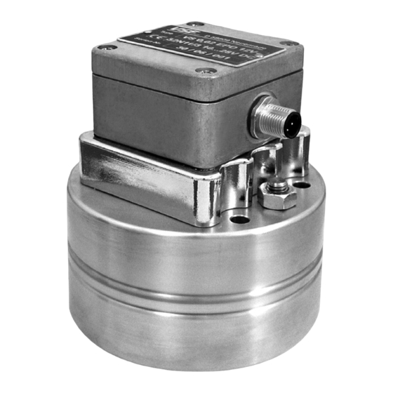
Page 4: General Function Description Of Flow Meter
Please follow all instructions in this operating manual; only this guarantees Opening the devices during the term of guarantee is only authorised after trouble-free operation of the flow meters . VSE is not liable for any damage consultation and approval of VSE . -
Page 5: Maximum Operating Pressure
= 450 bar /6500 psi Important: Please consult VSE for all operating pressures > 450 bar / 6500 psi and for special versions. • Statement to EU-Directive 97/23/EG, Pressurized devices VSE flow meter are pressurized devices according to article 1, paragraph The technical requirements for VSE flow meters therefore are limited to the 2 . -
Page 6: Flow Meter Range
(see flow meter total system . dimension sheet) . VSE supplies subplates for all flow meters of the “VSI” product line; they table 1: torque of fastening screws have various pipe threads and side or rearside connection (see subplates Flow meter, size (cast iron and 1.4305) -
Page 7: Cleaning And Flushing Of Pipe Lines Before Initial Start-Up
. You is in the pipe line, you can mount the flow meter and commence the initial can consult the suppliers and manufacturers of the fluid or contact VSE for start-up . -
Page 8: Flow Meters With High Definition Of Volume Measurement
90° (see fig . 3) . ved even more than is the case with conventional preamplifiers . VSE has In addition to the signal emission, a zero signal emission is provided, which... - Page 9 The preamplifier of the “VSI” product line has a programmed interpolation volume measurement V . The frequency multiplication “f*” lies between 1 factor (IPF) with which you can program new, different resolutions . Hence and 16 (see table 3) . you can program a resolution of 4 to 64 angular steps (see fig .
- Page 10 one measurement volume Vm 360° angle degrees channel 1. pulse Vm /1 channel channel Vm /2 channel 1. pulse 2. pulse 3. pulse 4. pulse channel Vm /4 channel channel Vm /8 channel channel 10 11 12 13 14 15 16 Vm /16 channel °...
- Page 11 500 000 16 .666 .7 0 .00166667 600 000 20 000 .0 0 .00125 800 000 26 666 .7 VSI 0.04… 0.04 ml/pulse 0 .04 25 000 4 l/min 1 666.7 Hz 1 666 .7 (= 4 000 ml/min 0 .02 50 000 3 333 .3...
- Page 12 Flow meter Vol. measurement Interpol. Vol. measure- K-factor* IPF* ment V (pulse/l) (Hz) (ml/pulse) VSI 1… 1 ml/pulse 1 .0 1 000 80 l/min 1 333.3 Hz 1 333 .3 (= 80 000 ml/min 0 .5 2 000 2 666 .7 = 1 333.3 ml/s) 0 .33333333 3 000...
-
Page 13: Technical Specifications Of Preamplifier
Example of flow meter “VSI 0.1/10 …” 1 . Column : Flow meter, version VSI and size 0.1 VSI 0 . 1 … physical volume measurement V 2 . Column: 0 . 1 ml/pulse (corresponds to the volume measurement V at interpolation factor IPF* = 1) 3 . -
Page 14: Plug Assignment Of Preamplifier
• Plug assignment of preamplifier Fig . 4 shows the plug assignment of the preamplifier . As you can see, this to the preamplifier housing and the meter . The cable shielding should al- plug has five pins, the outer four assigned exactly as the ones in standard ways be laid continuously as far as the flow meter and not interrupted in preamplifiers . -
Page 15: Sending Back Of Repairs And Sample Devices
. you must include a security sheet, which informs unambiguously, which fluid When returning flow meters to VSE Volumentechnik GmbH, please note that inspection and repair will only be performed if the safety specifica- was run with the flow meter and how dangerous this fluid is . -
Page 16: Flow Response Curves Vsi 0 .02 - Vsi 4
• Flow response curves VSI 0.02 – VSI 4 Flow Q Flow Q Flow Q Flow Q Flow Q Flow Q Flow Q Flow Q Flow Q Flow Q Flow Q Flow Q Flow Q Flow Q Flow Q Flow Q... -
Page 17: Dimensions Vsi 0 .02 - Vsi 4
• Dimensions VSI 0.02 – VSI 4 Cast iron version Stainless steel version Connection diagram View X Housing without milled edge Plug position for VSI 0 .02 to VSI 0 .4 and VSI 4 Centring bore hole Cast iron version Connection diagram Earth View X... -
Page 18: Dimensions, Subplates Ap . 02 - 4
• Dimensions, subplates AP. 02 - 4 Connection position, side Flow meter Subplate Size Connection øH thread / depth Weight thread 0.02 G 1/4“ 0.04 G 3/8“ M6/12 1 .8 G 1/2“ G 1/2“ M8/15 2 .7 G 3/4“ G 1/2“ G 3/4“... -
Page 19: Technical Specifications Vsi 10 / Ipf
• Technical specifications VSI 10 / IPF Size Measuring range Frequency Pulse value K-factor l/min /pulse pulse/litre VSI 10 1 .5 … 525 7 .50 * IPF … 2625 .67 * IPF 3 .333 / IPF 300 * IPF Adjustable interpolation factors IPF: 1; 2; 3; 4; 5; 8; 10; 12; 16 Measurement accuracy : up to 0 .5% of measurement value (with viscosity >... -
Page 20: Dimensions, Subplate Apg 10
• Dimensions VSI 10 View X Connection diagram O-ring Bar handle Lifting eye bolt Earth Weight 70 kg Lifting eye bolt Dimensions in mm • Dimensions, subplate APG 10. aPG 10 SG0N / 1 View X Connection surface VSI 10 Weight 21 kg aPG 10 SW0N / 1 View X... -
Page 21: Type Key
• Type key Flow meters VSI Type Codes VSI . . . (interpolation) Interior Example... -
Page 22: Plug Assignment
Subplates aP … Example • Plug assignment • Preamplifier-block wiring diagram... -
Page 23: Connection Diagram
CE-Déclaration de Conformité Wir, Nous, VSE Volumentechnik GmbH, Hönnestraße 49, 58809 Neuenrade/Germany erklären in alleiniger Verantwortung, dass die Produkte „Volumensensor“ mit der Typenbezeichnung: hereby declare in our sole responsibility, that the product “volumetric sensor“ with the type codes: déclarons de notre responsabilité, que le produit capteur volumétric type:... - Page 24 VSE Volumentechnik GmbH Hönnestraße 49 58809 Neuenrade / Germany Phone + 49 (0)23 94 /616 30 + 49 (0)23 94 /616 33 E-Mail info@vse-flow.com Internet www.vse-flow.com...
- Page 25 FU 252 Signal Converter Frequency-to-Analogue and Frequency-to-Serial • Input frequency range from 0.1 Hz to 1 MHz for full scale analogue output • Conversion time only 1 msec. (f > 3 kHz) • Analogue outputs +/- 10 V, 0 - 20 mA und 4 - 20 mA •...
- Page 26 Safety Instructions • This manual is an essential part of the unit and contains important hints about function, correct handling and commissioning. Non-observance can result in damage to the unit or the machine or even in injury to persons using the equipment! •...
- Page 27 Table of Contents 1. Compatibility Hint ..................4 2. Introduction ....................5 2.1. Impulse input formats and input levels..............5 2.2. Operating range ....................6 2.3. Suitable encoders and sensors ................6 3. Terminal Assignments and Connections..........7 3.1. Example for use of TTL encoders................ 7 3.2.
-
Page 28: Compatibility Hint
1. Compatibility Hint This product is a successor model of the thousandfold approved converter type FU251. The new product is suitable for a 100% replacement of the previous model, however some differences must be observed with DIL switch and parameter settings. Some essential advantages of FU252 compared to FU251 are: •... -
Page 29: Introduction
2. Introduction FU 252 is a small and low-cost, but highly performing converter for industrial applications, where one frequency or two different frequencies need to be converted into an analogue signal or a serial data format. The unit has been designed as a compact module with 12 screw terminals and a 9-position SUB-D connector (female). -
Page 30: Operating Range
Operating range 2.2. The full scale frequency (i.e. the input frequency where the analogue output reaches 10 V or 20 mA) can be set in a range from –1 MHz to +1 MHz. The operating range of the unit can be assigned to any frequency window inside this frequency range. -
Page 31: Terminal Assignments And Connections
3. Terminal Assignments and Connections We recommend connecting the Minus wire of the power supply to earth potential. Please observe that, under poor earthing and grounding conditions, multiple earth connections of screens and GND terminals may cause severe problems. In such cases it may be better to have only one central earthing point for the whole system. -
Page 32: Example For Use Of Htl Encoders
Example for use of HTL encoders 3.2. The encoder may be supplied from the same source as the converter, or from another source. +24V HTL encoder FU 252 Screen 12 (GND) Proximity switches, photocells etc. 3.3. These connections are fully similar to a HTL incremental encoder. With single channel operation, input B remains unconnected or can be used to select the output polarity. -
Page 33: Serial Interface
Serial interface 3.5. The unit provides a RS232 interface and a RS485 interface, however only one of the two can be used at a time. Serial communication allows to read out conversion results and to set parameters and variables by PC, according to need. GND int. -
Page 34: Dil Switch Settings
4. DIL Switch Settings There is one 8-position switch located on the top side (DIL1), and another 8-position switch is located on the bottom side of the unit (DIL2). These switches provide major settings of the desired properties of the unit. Changes of switch settings will become active only after cycling the power supply of the unit! Teach button... -
Page 35: Impulse Levels And Symmetric / Asymmetric Input Formats
Impulse levels and symmetric / asymmetric input formats 4.2. Positions 5 and 7 of DIL1 together with positions 3 to 6 of DIL2 allow setting of all imaginable combinations of levels and formats. • All subsequent tables use the following definitions: „0“... -
Page 36: Analogue Output Format
4.2.2. Settings for special applications Where you find that the standard settings shown before are not suitable for your application, please go through the following setting options and find out the input levels and characteristics you need. DIL1 DIL2 Characteristics of input A Characteristics of input B 5 6 7 3 4 5 6... -
Page 37: Selecting The Rs232 Or The Rs485 Serial Interface
Selecting the RS232 or the RS485 serial interface 4.4. Position 1 of switch DIL1 selects between the RS232 interface and the RS485 interface. All conection details have already been explained in section 3.5. DIL1 / 1 Serial Interface RS232 interface is active (RS485 is switched off) RS485 interface is active (RS232 is switched off) Teach function, Test function, Loading of default settings 4.5. -
Page 38: Commissioning
5. Commissioning With all basic applications, you can use the Teach feature for commissioning of the unit. Extended functions need a PC for setup and are described under section 7. As a first step it is advisable to check the input frequencies by means of the LED marked “Status”. -
Page 39: Conversion Of One Only Frequency (Single Channel Or Dual Channel With Direction Signal)
Conversion of one only frequency 5.1. (single channel or dual channel with direction signal) Make sure that the DIL switches are set according to the encoder you use, and that position 6 of switch DIL1 is OFF (Teach function active). Self test: Upon power up, both front LED’s must be lit first, and the yellow status LED must switch off after the self test has been concluded successfully (approx.1 sec.). -
Page 40: Pc Setup With Use Of The Operator Software Os3.X
6. PC Setup with Use of the Operator Software OS3.x You can apply the full set of functions when you use a PC and our operator software OS3.x for setup of the unit (at this time the actual version is OS3.2). Connect your PC to the converter, using a serial RS232 cable like shown in section 3.5 of this manual. - Page 41 Ex factory, all units use the following serial default settings: Unit No. 11, Baud rate 9600, 1 start/ 7 data/ parity even/ 1 stop bit If the serial settings of your unit should be unknown, you can run the „SCAN“ function from the „TOOLS“...
-
Page 42: Parameter Description
7. Parameter Description Parameter Description Register Setting These operands allow converting the result to the desired engineering (.8): units. This conversion affects the numeric value for serial read out from Multiplier register (:8) only, but not the scaling of the analogue output. Divisor With settings Multiplier... - Page 43 Parameter Description Frequency Control Frequency control and response characteristics to frequency gaps for channels A and B. This setting is taken as a 4 bit binary value. Range 00 – 15, default setting 10 (only to be changed in special case)*) Input Filter Programmable hardware filter for the impulse inputs...
- Page 44 Parameter Description Channel B Setting Sampling Time B Time base for measuring the frequency on input B Range 0 – 9,999 seconds Setting 0 provides a sampling time of 750 sec. Wait Time B Zero setting time for missing frequency on input B. Range 0.01 –...
- Page 45 Parameter Description Teach Mode This parameter is only important when your application provides a combination of the two inputs (e.g. A + B). The setting determines how to scale the total result of the selected A/B calculation Teach Mode = 0: The unit will automatically calculate a new “full scale”...
- Page 46 Parameter Description Serial Communication: Serial Unit No.: Especially with RS 485 applications it is necessary to attach a specific address to each unit, since up to 32 units can be connected to the same bus. You can choose any address number between 11 and 99. The address must however not contain a “0“...
- Page 47 Parameter Description Serial Timer: This register determines the cycle time in seconds for cyclic transmission when the Printer Mode is switched on. Range 0.001 to 9.999 seconds. With setting “0” all cyclic transmission is switched off and the unit will only send data upon request (PC mode *) Serial Value: Sets the code of the register of which the content should be sent with...
- Page 48 Parameter Description Both Channel Setting: These settings provide a final scaling of the calculation result from Multiplier: the combined operation modes A / B Divisor: Offset: Linearisation Setting: Interpolation points for linearisation (initial values) P1_x bis P16_x: Interpolation points for linearisation (substitute values) P1_y bis P16_y: (For clarification see section 9.) FU25201a_e_A5 / Nov-07...
-
Page 49: Free Programmable Linearisation
8. Free Programmable Linearisation This programmable feature allows the user to convert a linear input signal to a non- linear analogue output. There are 16 programmable x/y coordinates available, which can be set in any desired distance over the full conversion range. Between two coordinates, the unit uses linear interpolation. - Page 50 You can visualize your curve on the PC screen or by means of an external oscilloscope. For this, select TOOLS, then TEST and there „Analogue Voltage Function“. The unit will now simulate a repeating frequency course over the full range and generate the analogue signal accordingly.
-
Page 51: Monitor Functions
9. Monitor Functions The monitor function of the OS3.2 PC software allows to display some important data on the PC screen with a continuous refresh cycle. Select „Monitor“ from the „Tools“ menu to open the basic view of the monitor window. Click to “Define”... - Page 52 Click to the Status field, next to the desired register code (where you read ON or OFF). Now you can toggle this position between ON and OFF by touching any key. Set all of the register codes to ON which you afterwards would like to trace on the monitor. Switch all unused register codes to OFF.
-
Page 53: Data Readout Via Serial Interface
10. Data Readout via Serial Interface All register codes from section 9. are also available for serial readout by PC or PLC. For communication the FU252 converter uses the Drivecom Protocol according to ISO 1745. All protocol details can be found in our manual SERPRO_2a.doc To request for a data transmission you must send the following request string to the converter: C1 C2 ENQ EOT = control character (Hex 04) -
Page 54: Dimensions
11. Dimensions 91mm (3.583’’) 40 mm (1.575’’) 74 mm (2.913’’) Front view Side view Top view FU25201a_e_A5 / Nov-07 Page 30 / 33... -
Page 55: Specifications
12. Specifications Power supply 18...30 V DC Current consumption about 85 mA with 18 V, about 60 mA with 30 V (input voltage 24 V, aux. output unloaded) Aux. encoder supply +5.5V +/- 5% (max.: 250mA) Inputs (RS422/TTL differential) RS422 compatible (differential level min. 1 V) or TTL differential, f = 1 MHz Inputs TTL single-ended... -
Page 56: Internal Registers And Serial Codes
13. Internal Registers and Serial Codes Name Code CmdBit SerStatus BusStatus ExtStatus FreezeBoth 0040 FreezeB 0020 FreezeA 0010 ResetBoth 0008 ResetB 0004 ResetA 0002 ActivateData 1000 StoreEEProm 0001 Parameters Menu Name Code Default Register-Setting(:8) Multiplier -1000000 1000000 10000 Divisor 1000000 Offset -1000000 1000000... - Page 57 Menu Name Code Default Input-Setting InputConfiguration InputFunction Both-Channel-Setting Multiplier -1000000 1000000 10000 Divisor 1000000 10000 Offset -1000000 1000000 Linearisation-Setting P1(x) -100000 100000 100000 P1(y) -100000 100000 100000 P2(x) -100000 100000 100000 P2(y) -100000 100000 100000 P3(x) -100000 100000 100000 P3(y) -100000 100000 100000...
Need help?
Do you have a question about the VSI 0.04 and is the answer not in the manual?
Questions and answers