
Related Manuals for Sartorius Combics 2 CAIXS2


Summary of Contents for Sartorius Combics 2 CAIXS2
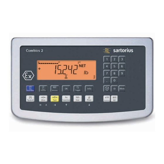
- Page 1 Operating Instructions Sartorius Combics 2 Ex Indicator Explosion protected scales for hazar for Use in Areas at Risk to Explosion Model CAIXS2 • F • A • A • V • V • N • S 98648-019-74 98648-019-74...
-
Page 2: Table Of Contents
Contents Contents Data Interfaces ..............99 Notes on Using these Instructions ........3 Communications Interface Configuration ....100 Warnings and Safety Precautions ..........4 Data Input Format ............101 Device Description ............... 5 Intended Use ................. 5 Printer Interface Configuration (Printer) ....103 General View of the Equipment .......... -
Page 3: Notes On Using These Instructions
Observe the safety instructions. These instructions are part of the product. Keep it in a safe and easily accessible location. If the instructions should be lost or misplaced, please contact Sartorius for a replacement or download the latest version from our website: www.sartorius.com... -
Page 4: Warnings And Safety Precautions
The operator shall be responsible for any modifications to the equipment and for any connections of cables or equipment not supplied by Sartorius and must check and, if necessary, correct these modifications and connections. -
Page 5: Device Description
It is robust electrical equipment and suitable for use in daily quality control in industry for the tasks previously specified. The Combics 2 CAIXS2 Ex-Indicator is designed for use with suitable scales or weighing platforms that correspond to the described technical specifications. To do this, the CAIXS2 and accessories must be used within the parameters of the specifications (see Appendix). -
Page 6: General View Of The Equipment
10 digit keypad for entering values Additional function keys (see “Operating Design") • Allows the connection of one analogue Sartorius platforms Combics IFXS4, IUXS4, or one IS-X precision platforms, Signum Ex scale or lo cells with suitable specifications to be connected in Zone 1, 21, 20 •... -
Page 7: Installation
Installation Installation When a CAIXS2 indicator is ordered with special equipment, the desired options come pre-loaded from the factory. Storage and Shipping Conditions Excessive vibrations may compromise the safety of the equipment. – Do not expose the equipment to unnecessarily extreme temperatures, moisture, shocks, blows or vibration. -
Page 8: Getting Started
5.) Carry out an alignment: Adjustment. Connecting Weighing Platforms You can connect any intrinsically safe, analog Sartorius platform to your CAIXS2 Indicator. Refer also to the Verification of Intrinsic Safety, the EC Type Examination Certificate for the CAIXS2 and the load cell or analog weighing platform to be connected. -
Page 9: Connecting A Weighing Platform
Getting.Started Preparing the Cable Strip approx. 14 cm from the end of the cable. Shorten the shielding to approx. 2 cm and pull back over the insulation. Strip approximately 5 mm of the insulation from the wires of the connecting cable and affix ferrules to the wire ends. - Page 10 Getting Started Instead of an analog/digital converter (ADC), you could also install a data interface to connect an intrinsically safe digital weighing platform or balance (e.g. an IS..-X). Connection using RS232 (Option A16) green brown yellow white gray Connection using RS485 (Option A19) RxD-TxD-P white RxD-TxD-N...
-
Page 11: Pin Assignment Chart
Getting Started Pin Allocations on the CAIXS2 Data Outputs (COM1) Option RS232 + RS422 RS485 + Pin*) Pin**) Digital I/Os Digital I/Os TxD-RxD_P TxD_N TxD_RxD_N TxD_P DRT_P RxD_N DTR_N UNI_IN UNI_IN CTS_N CTS_P RxD_P * 14-pin plug on adapter cable: ** 12-pin terminal block on the data adapter board: Plug the 12-pin connection cable into the corresponding type of data output (see data sheet External Data Interface). -
Page 12: Connecting The Device To Ac Power
If the voltage specified on the label or the plug design of the AC adapter do not match the rating or standard you use, please contact your Sartorius office or dealer. Check the voltage rating and plug design. -
Page 13: Operating Design
II 2D Ex ia IIIC T80° C Db Keys with no function Zero key Tare key • Allows the connection of one analogue Sartorius Function key unit conversion IFXS4, IUXS4, or one IS-X precision platforms, Si Start calibration or adjustment... -
Page 14: Key Functions
Operating Design Explosion protected scales for hazardous areas Key Functions • For use in Zones • ATEX: II 2G Ex II 2D Ex • Allows the conne IFXS4, IUXS4, or cells with suitable s • Verifiable class II • Very easy to read •... -
Page 15: Stored Settings
Operating Design Info key: Used to display application parameters and manual tare values (Info after pressing a follow-up key, e.g. )) Number block: Used to enter numeric values To apply the value, press the corresponding function key (e.g. key ) to save the entry as a manual tare value. -
Page 16: Display
Operating Design The Display There are two display modes: – display for weighing (weighing values and calculated values) – display in “Menu mode" (device settings). Display in Weighing Mode Appl. 1 Appl. 2 Appl. 3 Bar graph showing 10% intervals –... -
Page 17: Menu Operating Design
Operating Design Symbols for applications: An active application is identified by a line above and below the symbol ( Appl. 1 Appl. 2 Appl. 3 Application 1: “Counting"/ “Neutral Measurement" “Weighing in percent" “Averaging" (animal weighing) Application 2: “Checkweighing" “Classification" “Checkweighing toward zero"... - Page 18 Operating Design Entering Numbers and Letters (without a Number Block) – Press the key for less than 2 seconds: Activate character to the left of the currently active character (when first character is active: exit the input mode without saving changes) –...
-
Page 19: Configuration
Operating Design Configurations Basic settings are made in the Menu mode by selecting the desired parameters. These are divided into the following groups (first menu level); for menu structure see page 136: – Application parameter APPLIC. – Function key fn-key –... -
Page 20: Setting Up Password Protection
Operating Design y The small circle indicates that the setting has been saved. ° Use the ( key to exit the menu level to make additional settings if required. Press the ) key longer than 2 seconds to exit the menu. Setting Up Password Protection Turn on the device. - Page 21 Operating Design To apply a character, press the ) key. Enter all additional characters of the password as described above. Press and hold the ) key to save the password. Use the ( key to exit the menu level to make additional settings if required. Press the ) key longer than 2 seconds to exit the menu.
-
Page 22: Service Mode
Configuring Weighing Platforms Configuring Weighing Platforms Service mode Purpose The Service mode enables access to additional menu items in the Setup menu (setup) which are not displayed when the Service mode is not active. The most important calibration and adjustment work for the indicator and for the connected weighing platform can be carried out in the Service menu, e.g. -
Page 23: Configuring Weighing Platforms
Configuring Weighing Platforms Activating the Service Mode Switch to the Menu mode. Access the Setup menu. Select Setup. If a password is requested at this point, enter the service password (see Appendix) and continue with “Saving the service password." Access menu item U-CODE. Select ben.Code. -
Page 24: Analog/Digital Converter (Adc)
Configuring Weighing Platforms Analog/Digital Converter (ADC) Purpose Adjust the parameters of the analog/digital converter to the connected load cell or weighing platform. After ADC configuration, the ADC in connection with the load sensor is defined as a scale. Once the ADC configuration has been locked, the indicator can no longer be used to influence weighing results. - Page 25 Configuring Weighing Platforms CAL.UNIT Calibration/Adjustment unit 11.8 User-defined /o 11.8.1 FREE Grams /g 11.8.2 Kilograms/kg 11.8.3 Tons/t 11.8.21 SAVE Save configuration parameters 11.10 11.10.1 11.10.2 Operating Instructions Combics CAIXS2...
- Page 26 Configuring Weighing Platforms Setting Parameters for ADC Configuration Standard or verifiable configuration In ADC configuration, you must first select whether the weighing platform should be configured as a standard or verifiable (for use in legal metrology) weighing platform. – Standard configuration STANDRD (9.1.3) –...
- Page 27 Configuring Weighing Platforms Minimum load (min. load) When “Standard configuration” is used, this menu item is not displayed. The minimum load of the connected weighing platform is entered under this menu item. The minimum load for scales of class l is 20 e and 10 e for class m. Attention: The function of the minimum load setting is to warn operators that below this limit, the summation of tolerances might lead to significant measure- ment errors.
-
Page 28: Configuring An Adc
Configuring Weighing Platforms Configuring the A/D Converter (ADC) The weighing platform must already be connected. Opening the Menu Access Switch The menu access switch is located on the back of the indicator, behind the cover. Remove the cap. Slide the switch to the right (= “open" position). Menu Access Switch/Calibration Switch Cover Switch off and restart the device. -
Page 29: Geographical Data
Configuring Weighing Platforms The A/D converter can now be treated like a standard weighing platform in connection with the load sensor. Close the menu access switch (left position) and reattach the cap. Once ADC configuration has been completed, an adjustment of the weighing platform (calibration/adjustment and linearization) must be carried out (see “Calibration/Adjustment without Weights"). - Page 30 Configuring Weighing Platforms Procedure Open menu access switch. If the device is part of a verified weighing facility, this will only be possible if the verification seal is broken. The weighing equipment must then be verified again. Activate the Service mode. Select the weighing platform.
-
Page 31: Entering Adjustment And Linearization Weights
Configuring Weighing Platforms Entering Adjustment and Linearization Weights Purpose Entering adjustment and linearization weights. Setup information – The Service mode must be activated in order for linearization weights to be entered under menu items 1.18.2 to 1.18.5 (see page 17). Adjustment and linearization weights are entered in the Setup menu under –... -
Page 32: External Linearization
Configuring Weighing Platforms External Linearization Setup information – External linearization when weighing in legal metrology is only possible when the menu access switch is open. The “external linearization" function must be allocated to the J key – (menu item 1.9.6 or 1.9.7). Once linearization has been completed, the J key must be reallocated back to its original function in the Setup menu, e.g. -
Page 33: Setting The Preload
Configuring Weighing Platforms Set preload Setup information – Setting the preload when weighing in legal metrology is only possible using the “Zero at Power On" menu item. The “Set Preload" function (menu item 1.9.8) must be allocated to the J key. –... -
Page 34: Deleting The Preload
Configuring Weighing Platforms Clearing the Preload Setup information – Clearing the preload when weighing in legal metrology is only possible using the “Zero at Power On" menu item. – The “Clear Preload" function (menu item 1.9.9) must be allocated to the J key. -
Page 35: Adjustment Without Weights
Configuring Weighing Platforms Adjustment without Weights In the Service menu, adjustment without weights can be carried out by entering the characteristic data of the load cells. Adjustment without weights may not be carried out on weighing equipment used in legal metrology. Setup information –... -
Page 36: Operation
Operation Operation Weighing This application is always available during operation. Zeroing by pressing ( Features: – Storing the weight on the platform as a tare by pressing ) – – Taring container weight automatically – Using a 10-key keypad to enter tare weight Deleting tare values by entering 0 and ) / c and ) –... - Page 37 Operation Automatic printing (PROTOC menu item 7.15): When the menu item (7.15.2) is active, the first weight value that exceeds the minimum load is printed. If the menu item is also activated for automatic taring, it is only tared when the minimum load is exceeded.
-
Page 38: Adjustment/Configuration Counter
Operation Adjustment/Configuration Counter for Standard cales Purpose Automatically record changes to adjustment and weighing parameters using two independent counters. The values remain saved for the life of the device. To display both counters, press and hold the ( key for longer than 2 seconds. -
Page 39: Device Parameters
Operation Device Parameters Password Protection Access to the Setup device parameters and the APPLIC application parameters can be password-protected against unauthorized changes in the Setup menu under U-CODE (see page 38). Keypad The keypad can be blocked and released for entry (menu item 8.3) in the SETUP menu under UTILIT / PARAMETER / KEYS. - Page 40 Operation Place the container on the weighing platform. y The container weight is displayed. Press the ) key to tare the scale. y The display for a tared scale with a container appears. Place a sample in the container (in this example, 120.2 g). y The display for a tared scale with weighing results appears.
- Page 41 Operation Press the p key to print a report. EISENSCHMIDT GOETTINGEN 8/12/2013 3:10 PM -------------------- 170.2 g 50.0 g 120.2 g -------------------- Example Weighing: Enter value for tare using the numeric keys; print results. Turn on the device. All display segments appear (display test). y The display for no load on the scale appears.
- Page 42 Operation y The gross value is displayed. You can toggle between the gross and net display using the L key. Press the p key to print a report. GMP header (only if GMP-compliant -------------------- printout is configured, menu 7.13) 8/12/2013 3:15 PM Type CAIXS2...
-
Page 43: Calibration, Adjustment
Operation Calibration and Adjustment Purpose Calibration determines the difference between the value displayed and the actual weight on the platform. Calibration does not entail making any changes within the weighing equipment. During adjustment, the difference between the measured value displayed and the true weight of a sample is corrected, or is reduced to an allowable level within maximum permissible error limits. - Page 44 Operation Example 1 External calibration and manual adjustment with default weights (weighing parameters: factory settings). 1.) Zero the scale. 2.) Start calibration (e.g. when adjustment prompt flashes WP symbol). cal.Ext. is displayed for two seconds. You are prompted to place the required weight on the platform (e.g.
- Page 45 Operation A GMP-compliant printout is generated. -------------------- 02/24/2013 10:15 Type CAIXS2 Ser.no. 12345678 Vers. C2 100.280810 Software versions 01-26-03 to 01-26-30 can be printed. BVers. 01-26-03 -------------------- Ext. Calibrate Targ. 10000 g Diff. + Ext. Adjustment Diff. + -------------------- 02/24/2013 10:15 Name: --------------------...
-
Page 46: Sqmin Function
Operation 4.) Position the calibration/adjustment weight on the weighing platform. The adjustment weight is displayed once adjustment is finished. Remove the adjustment weight from the weighing platform. SQmin Function Purpose To display the allowable minimum sample quantity “SQmin" (sample quantity minimum) in accordance with the United States Pharmacopoeia (USP). - Page 47 Operation SQmin Operation Example Determining sample weights while monitoring the minimum sample quantity (in this example, SQmin: 100 g). Default setting: The SQmin display must be turned on. Place the container for the sample on the scale and tare. Place the sample on the scale. y The minimum sample quantity is not reached (symbol k).
-
Page 48: Data Id Codes
Operation Individual ID Codes (Identifiers) You can assign codes (such as product name, batch number, etc.) for identification of measured values on printouts. Features – You can assign up to six ID codes. – One name and one value can be assigned to each ID code. Displaying individual IDs: press the d key. - Page 49 Operation Using Individual ID Codes Example Enter ID code names. “Batch number" and “Customer" should be entered for ID 1 and ID 2. Open the menu. Select and open SETUP. Select and open PRINT. Open PROTOC.. Open HEADLIN. Select and open INDENT. 1. Enter the name for the first identification (use the k and p keys or the number block), e.
-
Page 50: Application Programs
Operation Application Programs Overview of Applications and Functions Usage Basic weighing Send print job/data record to peripheral device X Label printer Second scale connection option optional (WP-2 using COM1) Counting Neutral measurement Averaging (animal weighing) Weighing in percent Verification Classification Totalizing Batching/counting to target value Product data memory... -
Page 51: Counting Z
Operation Counting With the Counting application, you can determine the number of parts to each have approximately equal weight (menu APPLIC.1). Features – Save the reference weight “wRef" from the weighing platform. – Enter the reference sample weight “wRef" using the keypad. –... - Page 52 Operation Entering the Reference Piece Weight The reference piece weight (i.e. the weight of one piece) can be entered using the keypad and saved with the O key. The entered value remains active until deleted by pressing the c key or overwritten by a new value.
- Page 53 Operation Resolution The resolution indicates the accuracy used to determine the reference weight. The default setting is “display resolution." The resolution is increased when “10-fold" or “100-fold" is selected. “10-fold" increases the resolution of the net value by one step (display resolution x 10), “100-fold" increases it two steps (display resolution x 100).
- Page 54 Operation The system can be configured to switch automatically to the reference platform for initialization (the measured value line shows Ref). Following initialization, you can switch to the counting platform. Setting: APPLIC./APPLIC.1/COUNT./REF.WP menu item 3.13. If automatic reference sample updating is enabled, the update is performed on the active platform;...
- Page 55 Operation y The result is displayed. y If automatic reference sample updating is enabled, Opt appears in the display. Print results (Configuring Printouts see page 96). nRef 38 pcs wRef + 0.003280 kg 0.373 kg 0.248 kg 0.125 kg 38 pcs -------------------- Operating Instructions Combics CAIXS2...
-
Page 56: Neutral Measurementz Nm
Operation Neutral Measurement Z nM With this application you can measure the length, surface and volume of parts that have roughly the same specific weight. The o symbol is displayed as the unit (menu APPLIC.1). Features – Save the reference weight “wRef" from the weighing platform. –... - Page 57 Operation How the reference weight is calculated depends on the application setting for resolution. The resolution settings are either display resolution, display resolution 10-fold or display resolution 100-fold. Entering the Reference Weight The reference weight (e.g. the weight of one meter of electrical cable) can be entered using the keypad and saved by pressing the O key.
- Page 58 Operation Minimum load for initialization You can set the minimum load here, i.e., the load that must be placed on the weighing platform in order to carry out the application. If the load on the platform is too light, the following will occur: –...
- Page 59 Operation Following initialization, you can switch to the counting platform. Example: 25 m of electrical cable is to be measured. Configuration: The “Neutral Measurement" application is selected, and printout has been set up (see “Configuration"). Place empty container on the scale. Tare the scale.
-
Page 60: Averaging (Animal Weighing) V
Operation Averaging (Animal Weighing) With this application, you can calculate averages from several weighing operations. It is used when either the object to be weighed (e.g. animals) or the environment during weighing are unstable. Selection and settings in the Applic. / Applic.1 / ANIM.WG menu. - Page 61 Operation – Manual start with user-defined number of subweighing operations: Place the sample on the platform and enter the number of weighing operations using the keypad. Press the r key to save the number entered and begin weighing. – Automatic start with preset number of subweighing operations: Measurement begins when you place the first sample on the platform, provided the start conditions are met.
- Page 62 Operation The minimum load can be set in 10 steps, from 1 to 1000 digits (see Available parameters). The “digits" here refer to the scale intervals in the connected weighing platform. If the interval of the connected platform is 1 g, for example, and 1000 digits are required, you must place at least 1000 g (= 1000 intervals = 1000 digits) on the weighing platform for initialization.
- Page 63 Operation Set the number of reference parts using r: 1, 2, 5, 10, 20, etc. Start the calculation of the reference piece weight. The averaging routine does not begin until the fluctuation in weight value remains below a defined threshold over three consecutive measurements. The number of subweighing operations remaining is shown in the numeric display.
-
Page 64: Weighing In Percentl
Operation Weighing in Percent With this application, you can use your weighing platform to obtain weight readouts in percent which are in proportion to a reference weight. L is displayed as the weight unit. Selection and settings in the Applic. / Applic.1 / PERCENT menu. - Page 65 Operation Entering the Reference Percentage Value The reference weight for 100% is entered using the keypad and the O key is pressed to initialize the application. The entered value remains active until deleted by pressing the c key or overwritten by a new value. It remains saved after the scale is switched off. Preparation Open the APPLIC./APPLIC.1/PERCENT menu.
- Page 66 Operation Setting: Applic./Applic.1/PERCENT/Min.init menu item 3.6. The minimum load can be set in 10 steps, from 1 to 1000 digits (see Available parameters). The “digits" here refer to the scale intervals in the connected weighing platform. If the interval of the connected platform is 1 g, for example, and 1000 digits are required, you must place at least 1000 g (= 1000 intervals = 1000 digits) on the weighing platform for initialization.
- Page 67 Operation Example: 100% of a sample material should be weighed. Configuration: The “Weighing in percent" application is selected, and printout has been set up. Place empty container on the scale. Tare the scale. This is not required if the automatic tare function is active. The tare weight is saved automatically when you place the container on the platform.
- Page 68 Operation Print the results. Printout Configuration, see page 96. pRef 20 % wRef 0.085 kg 1.080 kg 0.675 kg 0.423 kg 100 % ------------------- Operating Instructions Combics CAIXS2...
-
Page 69: Checkweighing
Operation Checkweighing With this application, you can check whether the sample on the weighing platform matches a target value or lies within a given tolerance range. Checkweighing also makes it easy to fill sample materials to a specified target weight. Selection and settings in the Applic. - Page 70 Operation A tare value entered manually overwrites a stored tare value (weight value). If you enter a tare value manually, a tare value (weight value) stored later overwrites the manually entered value. Setting: Applic./TARE.FNC menu item 3.25.2. Restore factory default settings: Applic./Reset menu item 9.1. Target value Checkweighing entails comparing the current weight value to a defined target value.
- Page 71 Operation CTRL.SET Activate SET control output “SET" output 4.3.1* OUTPUT Ready to operate 4.3.2 OP.READY OUTP.ACT Port lines 4.4.1 Always on. 4.4.2 ALWAYS On at stability 4.4.3 STABIL On within checkweighing range 4.4.4* CHECK.RG On at stability within checkweighing STAB.CHK range 4.4.5 INPUT Parameter input...
- Page 72 Operation In the Applic./Applic.2/CHECK.WG/OUTP.ACT menu, menu item 4.4, you can choose the following settings for the control outputs: – – always on – activated at stability – on within the checkweighing range – on at stability within checkweighing range. Checkweighing range Checkweighing range 30 % Target weight...
- Page 73 Operation Example 1: Checkweighing samples with a target weight of 1250 g and a tolerance range from -10 g to +30 g. The tolerance values should be entered as absolute values (lower and upper tolerance limit). Configuration: The “Checkweighing" application is selected using the setting INPUT / TAR.MN.MX, a printout has been set up (see “Configuration").
- Page 74 Operation y The LEDs next to the display indicate the results: yellow LED: sample too heavy green LED: sample in tolerance range red LED: sample too light. Print the results. Note: If automatic printout of results is enabled, you do not need to press the p key.
- Page 75 Operation Enter the maximum lower deviation (in this example, 10 g). Save the lower limit value. y The maximum symbol flashes at the top of the display. Enter the maximum upper deviation (in this example, 30 g). Save the upper limit value. Proceed as described in example 1.
- Page 76 Operation Save the upper limit value. Remove the sample with the target weight from the weighing platform. The samples can now be checked one after the other. y The LEDs next to the display indicate the results: yellow LED: sample too heavy green LED: sample in tolerance range red LED: sample too light.
-
Page 77: Classification
Operation Classification With this application, you can determine whether the weight of a given sample lies within the limits of a defined weight class (Applic.2 menu). Features – Classification with 3 or 5 weight classes. Setting: Applic./Applic.2/CLASS./PARAM.2/QTY. menu item 4.8. –... - Page 78 Operation By entering a percentage: The upper value of Class 1 is entered using the keypad or by saving the value indicated. Upper limits for the other classes are defined by entering a percentage of deviation from the upper limit of Class 1, using the keypad.
- Page 79 Operation Minimum load for initialization You can set the minimum load here, i.e., the load that must be placed on the weighing platform in order to carry out the application. If the load on platform is too light, then this is class 0. Setting: Applic./Applic.1/Count./Min.init menu item 3.6.
- Page 80 Operation In the Applic./Applic.3/CLASS./Param.2/OUTP.ACT menu, menu item 4.7, you can choose the following settings for the control outputs: – – always on – activated at stability. The “SET” output normally changes its voltage level when the current weight exceeds the minimum load. Alternatively, you can assign the “Ready for use” function to this port.
- Page 81 Operation y The result is displayed. Print the results. Note: If automatic printout of results is enabled, you do not need to press the p key. The results are printed automatically. Printout Configuration, see page 96. Lim1 0.110 kg Lim2 0.130 kg 0.118 kg 0.000 kg...
-
Page 82: Totalizings
Operation Totalizing With this application, you can add weights to the totalizing memory. In addition to weight values, the number of separate values added to memory is also saved (APPLIC.3 menu). Features – You can weigh up to 999 items. –... - Page 83 Operation – Value saved automatically when the weighing platform is stable and the defined minimum load is exceeded. If the defined minimum load is not exceeded, you can save the item manually by pressing the O key. Regardless of these settings, the current value cannot be saved automatically unless the platform is unloaded before the next sample is placed on it.
- Page 84 Operation Example: Totalizing weight values. Configuration: The “Totalizing" application is selected, and printout has been set up. Setting: SETUP / PRINT/PROTOC. menu item 7.6. Component log: menu item 7.7. Total data record: menu item 7.8. Place the first weight on the weighing platform. y The weight value is displayed.
- Page 85 Operation Toggle the display between individual value and total. End totalizing. y Configured total data record is printed. 1.346 kg 0.346 kg 1.000 kg ------------------ Operating Instructions Combics CAIXS2...
-
Page 86: Net Total Formulation R
Operation Net Total Formulation With this application, you can weigh in different components up to a defined total. Each component is saved in the net-total memory (Applic.3 menu). Features – Weigh in up to 999 components in series. Net total formulation cannot be combined with level 1 and 2 applications –... - Page 87 Operation Minimum load The minimum amount that a component must weigh before it can be saved in net- total memory. Setting: APPLIC/ APPLIC.3/NET.TOT. Menu item 3.6. Once the limit is exceeded by the load, the value can be saved. If the load on platform is too light, the following will occur when you try to save a value: –...
- Page 88 Operation Tare scale. This is not required if the automatic tare function is active. The tare weight is saved automatically when you place the container on the platform. y The prompt to fill and save the first component is shown. Place the first component into the container (in this example, 1100 g).
- Page 89 Operation y The value displayed equals the weight of components added up to now plus the current weight on the platform. Place the third component into the container until the desired total weight is reached (in this example, 2000 g). y The total weight is displayed.
-
Page 90: Combining Application Programs
Operation Combining Application Programs The following table shows how the applications described can be combined. The basic weighing function is available at all times; it does not need to be combined with a computational function. Select programs one after the other: Toggle using the D key. Application 1 Application 2 Application 3... - Page 91 Operation Place any number of parts in the container for the reference quantity (in this example, 10 pcs). Start the calculation of the reference piece weight. y If the weight is too light, an error code is shown in the main display Inf 29. Reduce the minimum load setting or increase the reference sample quantity setting and the number of parts in the container.
- Page 92 Operation y The number of pieces is saved automatically. Unload the scale: Remove the samples. Perform further counting operations as desired. Toggle display from individual value to total. End the portioning options and print the final evaluation. Configured printout: Total. -------------------- nRef 10 pcs...
-
Page 93: Configuring Printouts
Operation Configuring Printouts Purpose You can individually define each measurement printout. This should be carried out after setting the applications since some data in the printout is application- dependent. In the “Print parameters" menu, single, component, and total data records can be configured, which contain the available print items for the respective applications. - Page 94 Operation Result interface 2 7.12 TOTAL 2 ISO/GMP 7.13 gmp.prot Date without time 7.14 DAT/TIM Automatic printout after stability 7.15 AUT.ONCE Flex print 7.16 FLEX. PRN Decimal separator 7.17 DEC.SEP. Alibi memory 7.18 ALIB.MEM RESET Restore factory default settings Setting the factory settings –...
- Page 95 Operation Example: Standard printout for data output from the “Counting" application. Configuration: – Application: Application 1: Counting Then access Setup: Printout: Printer 1: “Individual: print by pressing p" – Select the Setup menu. Select and open the Printsubmenu. PROTOC. submenu should be selected and opened. Press the ) key until header appears in the display.
- Page 96 Operation Press the ) key to save the selection. . y The counter value is increased by one. Press the k key until the “reference weight" entry is displayed..Press the ) key to save the selection. You can now select additional print items in the same way. To exit print item entry, press the ( key until APPLIC.
-
Page 97: Product Data Memory
Operation Product Data Memory Purpose The product data memory stores initialization data and user data (product and tare values). Features – The product data memory has 100 memory cells for product or tare values. This means that e.g. 80 application memories and 20 tare memories are available. –... - Page 98 Operation Example: Using the Counting application with a stored average piece weight. Configuration: Application: Counting (COUNT.) Saving the Average Piece Weight Start the application. Determine the average piece weight using one of the methods described above. Enter the memory cell number using the keypad, and press and hold the R key (min 2 seconds).
-
Page 99: Data Interfaces
The interface can be configured in the Setup menu for different input and output functions (e.g. printer, 2nd weighing platform, PC). Warning when using third-party RS-232 connecting cables: the pin assignments may not be compatible with Sartorius equipment. Specifications Serial interface:... -
Page 100: Communications Interface Configuration
Data interfaces Configuring the Data Interface as a COM Port datprot You can configure the interface as a COM port in either COM1 or UniCOM, “Data Protocol" (datprot) menu item. SBI communication This is a simple ASCII interface. Data output is configured under menu items 6.1 and 6.3: –... -
Page 101: Data Input Format
Data interfaces Data Input Format You can connect a computer to your scale to send commands controlling weighing instrument functions and applications via the interface port. All commands use the same data input format. They begin with the character ESC (ASCII: 27) and end with a carriage return CR (ASCII: 13) and LF (ASCII: 10). - Page 102 Data interfaces Each line in a print job can contain up to 22 characters (up to 20 printable characters plus two control characters). The first 6 characters, called the “data header”, identify the subsequent value. You can suppress the header under menu item 7.2 in the “Printouts”...
-
Page 103: Printer Interface Configuration (Printer)
Data interfaces Example: Output weight value of +1255.7 g Position 1 10 11 12 13 14 15 16 CR LF Position 1: Plus +, or minus - or space Position 2: Space Positions 3-10: Weight value with decimal point. leading zeros are output as spaces. - Page 104 Data interfaces Error Message 4 5 6 7 8 9 10 11 12 13 14 15 16 17 18 19 20 21 22 t a t * * * * * U * * # # * * CR LF t a t * * * * * U * # # #...
- Page 105 Data interfaces If the weight value is output with 10-fold increased resolution, this value is not permitted to be printed or saved in a weighing instrument operated in legal metrology in the SBI mode. In this case, the unit symbol is not included with output.
-
Page 106: Configuring A Printout
Data interfaces Configuring a Printout Printouts are configured in the Setup menu under “Printouts" (setup / print / protoc.). This should be carried out after configuring the application since some data in the printout is application-dependent. You can configure a separate printout for each interface. Each printout is comprised of different information blocks that can be activated or deactivated via multiple selection in the menu. - Page 107 Data interfaces Weighing platform WP 1: Dash line -------------------- Date/time 14.01.2013 09:43 Combics Type Type CAIXS2 Combics serial no. Ser.no. 12345678 Software version Application Vers. C2 100.280810 Software version Basic software BVers. 01-62-03 Dash line -------------------- Weighing platform WP 2 (xBPI printout): Dash line -------------------- Date/time...
-
Page 108: Sample Printouts
Data interfaces Sample Printouts For details on the individual information blocks, see “Configuring Printouts" above. For details on configuring the header lines, refer to the chapter of the respective application. “Weighing” application: If selected, an empty line will be printed. HEADER LINE1 HEADER LINE2 1/14/2013... - Page 109 Data interfaces “Neutral Measurement” Application: “Checkweighing” Application: The initialization data block contains the reference The initialization data contains the target weight, the min. weight, sample quantity and reference weight. The results block and the max. weight. The results data always contains the gross, contains gross, net and tare weight and the piece count net and tare weight.
- Page 110 Data interface GMP-Compliant Printouts Example with 2 transactions: Clearing the preload printout HEADER LINE1 -------------------- "Linearization" printout HEADER LINE2 1/14/2013 1:50 PM -------------------- 1/14/2013 9:43 AM Type CAIXS2 1/14/2013 1:00 PM -------------------- Ser.no. 12345678 Type CAIXS2 1.400 kg Vers. C2 100.280810 Ser.no.
-
Page 111: Error Messages
Err 54 Weighing pan is not in place Position the weighing pan Key is stuck Release key or contact your local Sartorius Service Center ERR 101–104 Key pressed when switching on Operating program memory faulty Contact your local Sartorius Service Center... -
Page 112: Care And Maintenance
Care and Maintenance Care and Maintenance Service Regular servicing by a Sartorius technician will extend the service life of your equipment and ensure its continued weighing accuracy. Sartorius offers its customers service contracts with regular maintenance intervals ranging from one month to two years. -
Page 113: Safety Inspection
Disconnect the power supply to the device (unplug the power cord from the mains supply) and make sure the device cannot be used for the time being. Notify your nearest Sartorius Service Center. Maintenance and repair work may only be carried out by service technicians: –... -
Page 114: Disposal
In Germany and several other countries, Sartorius itself assumes responsibility for the return and conformant disposal of its electronic and electrical products. Such equipment may not be thrown out with household waste or brought to collection centers run by local public disposal operations –... -
Page 115: Specifications
Storage temperature -20°C to +60°C, operating temperature -10°C to +40°C Power supply Only via suitable and where applicable country-specific EX power supply provided by Sartorius model YPS02-X.. / YPS02-Z.. / YPSC01-X / YPSC01-Z: 100-240Vac (± 10%), 50/60Hz; max. 25VA or 40-80VA with YPSC01-. or via Ex battery pack YRB02-X... -
Page 116: Dimensions (Scale Drawings)
CAIXS2 Dimensions CAIXS2 Dimensions Kabellänge 200mm / cable length 200mm 26.5 146.5 All dimensions are given in millimeters Operating Instructions Combics CAIXS2... -
Page 117: Accessories
Interface converter made of stainless steel for installation in non-hazardous area, for connection of peripheral devices in non-hazardous area, in version RS-232-RS-232 or RS-422-RS-232 YDI05-Z 2 dust covers for CAIXS2 YDC01CI-X SNLE Sartorius Nice Label Express YAD02IS WinScale YSW03 SartoCollect YSC02 Sartorius GMP Connect... - Page 118 AC adapter outside explosive atmospheres 24 V ATEX YPS02-XV24 ATEX Zone 20/1/21/2/22 Safe Area: Only use cables and cable lengths approved by Sartorius, cables not provided by Sartorius are the responsibility of the operator. YPS02-XV24 AIS to con ATEX Operating Instructions | Betriebsanleitung Sartorius YRB02-X...
-
Page 119: Declaration Of Conformity
“Installation” Service in Germany Our “Installation" service package provides the following services: – Installation – Commissioning – Inspection – Training If you would like Sartorius to install the indicator, please request this service from a customer service employee. Operating Instructions Combics CAIXS2... -
Page 120: Declaration Of Conformity
Declarations of Conformity Operating Instructions Combics CAIXS2... - Page 121 Declaration of Conformity Operating Instructions Combics CAIXS2...
-
Page 122: Ex Safety Notes
EX conformity and in the forfeiture of all claims under the manufacturer's warranty. Only authorized specialists may open the equipment by working to Sartorius rule. Modifications, including those to be carried out by Sartorius employees, may be permitted only after the express written authorization has been obtained from Sartorius. - Page 123 Operating Instructions Combics CAIXS2...
-
Page 124: Menu Structure
Menu Structure Menu Structure Overview of the complete menu structure; the individual setting parameters are listed on the following pages. The indicator only displays the menus that correspond to the available hardware. Set and select applications (see page 137) APPLIC. Basic weighing function, Counting applications z , Neutral measurement znM, Animal weighing j, - APPLIC.1 Weighing in percent %... - Page 125 Menu Structure Menu Applications * = Factory setting Weighing APPLIC./ APPLIC.1 WEIGH. Counting APPLIC./APPLIC.1/ COUNT. MIN.INIT Minimum load for application 1 scale interval 3.6.1* 1 DIGIT 2 scale intervals 3.6.2 2 DIGIT ... see “Weighing" 1000 scale intervals 3.6.10 1000 d RESOLUT Resolution for calculation of reference value DISP.ACC.
- Page 126 Menu Structure REF.WP Reference weighing instrument 3.13 No weighing platform selected 3.13.1* NO WP Weighing platform 1 3.13.2 WP 1 Weighing platform 2 3.13.3 WP 2 Neutral Measurement APPLIC/APPLIC.1 neutr.m MIN.INIT Minimum load for application 1 scale interval 3.6.1* 1 DIGIT 2 scale intervals 3.6.2 2 DIGIT...
- Page 127 Menu Structure DEC.PLCS Decimal place in displayed result 3.10 none 3.10.1 WITHOUT 1 decimal place 3.10.2 1 Dec.Pl 2 decimal places 3.10.3 2 Dec.Pl. 3 decimal places 3.10.4 3 Dec.Pl. SAVE WT. Parameter for saving weight values 3.11 With stability* 3.11.1 STABIL ACC.STAB With increased stability*...
- Page 128 Menu Structure PRINT Automatic printing 4.10 manual 4.10.1* MANUAL automatic 4.10.2* AUTOMAT Applic.3 NET.TOT. Net-Total APPLIC/ APPLIC.3 MIN.INIT Minimum load for application 1 scale interval 3.6.1* 1 DIGIT 2 scale intervals 3.6.2 2 DIGIT ... see “Weighing" 1000 scale intervals 3.6.10 1000 d PRT.SAV.
- Page 129 Menu Structure Resets all applications to factory settings APPLIC. / RESET RESET Restore all applications to factory default settings Yes (restore factory settings) 9.1.1 No (retain user-defined settings) 9.1.2* Menu Key Assignment for the k key not assigned * = Factory settings fn-key 2ND.UNIT Display 2nd unit*...
- Page 130 Menu Structure Tola/tol 1.7.18 TOLA Baht/bat 1.7.19 BAHT Mesgahl/MS 1.7.20 MESGHAL tons/t 1.7.21 1.DIS.DIG. Display accuracy all digits 1.8.1* -1.WT.CHA reduced by one digit 1.8.2 10-fold increased resolution 1.8.14 RES.*10 Increase resolution by 2 scale intervals 1.8.15 +DIV. 2 Increase resolution by 1 scale interval 1.8.16 +DIV.
- Page 131 Menu Structure setup / WP-1 / intern. Param.2 2ND.UNIT 2nd weight unit (depends on the weighing platform type) not for use in legal metrology gram/g 3.1.2* GRAM Kilograms/kg 3.1.3 KILOGR. carats/ct 3.1.4 CARAT pounds/lb 3.1.5 POUND ounces/oz 3.1.6 OUNCE troy ounces/ozt 3.1.7 TROY.OZ.
- Page 132 Menu Structure dat.prot Data protocols setup /com-1 SBI* Config. BAUD Baud rate 5.1.1 5.1.2 5.1.3 1200 5.1.4 1200 2400 5.1.5 2400 4800 5.1.6 4800 9600 5.1.7* 9600 19200 5.1.8 19200 PARITY Parity Space SPACE Only if 7 data bits is selected 5.2.2 5.2.3* Even...
- Page 133 Menu Structure PRINTER Printer configuration SETUP /COM-1 YDP20 CONFIG. BAUD Baud rate 1200 5.1.4* 1200 2400 5.1.5 2400 4800 5.1.6 4800 9600 5.1.7 9600 19200 5.1.8 19200 PARITY Parity Space SPACE Only if 7 data bits is selected 5.2.2 5.2.3* Even 5.2.4 EVEN...
- Page 134 Menu Structure setup / CTRL IO Input Paramet. EXT.KEYB Function for external key Trigger p key function* 8.4.1 PRINT PRNT.LNG. Trigger p key function (press and hold) 8.4.2 Trigger ) key function 8.4.3 TARE ISO.TEST Trigger J key function 8.4.4 Trigger k key function 8.4.5 SCALE.NR Trigger n key function...
- Page 135 Menu Structure setup / print PROTOC. Printouts HEADLIN. Header entry Line 1 7.4.1 LINE 1 Line 2 7.4.2 LINE 2 Identifier 1 7.4.3 IDENT. 1 Identifier 2 7.4.4 IDENT. 2 Identifier 3 7.4.5 IDENT. 3 Identifier 4 7.4.6 IDENT. 4 Identifier 5 7.4.7 IDENT.
- Page 136 Menu Structure setup / UTILIT. 8 PARAMET Keys Unblock keys Release all 8.3.1* ALL + All blocked 8.3.2 - ALL -NUM.PAD Number pad locked 8.3.3 -SCALE.N n key locked 8.3.4 key ( locked 8.3.5 - ZERO key ) locked 8.3.6 - TARE key k locked 8.3.7...
- Page 137 Menu Structure setup / SQmin DISPLAY SQmin value display GMP PRT. GMP-compliant printout setup / alib.mem Deletes the Alibi memory (Service only) CLEAR Entry of the save intervals in days (0 to 255) PERIOD Menu Info (Device Information) * = Factory setting Service date INFO / SERVICE Input: day.month.year (e.g.
- Page 138 Menu Structure ADC Settings Menu ADC.CON standrd Standard configuration 9.1.3 RANGE Ranges 11.3 Single-range scale 11.3.1 SINGLE Multi-interval scale 11.3.2 MULT.INT Multiple-range scale 11.3.3 MULT.RNG Single-range scale 11.4 SINGLE Scale interval d 11.4.1 Max. load 11.4.4 MULT.INT Multi-interval scale 11.5 Scale interval d 11.5.1 Range 1...
- Page 139 Menu Structure WT.UNIT Available weight units 11.7 User-defined /o 11.7.1 FREE Grams /g 11.7.2 Kilograms/kg 11.7.4 … Tons/t 11.7.21 Pound:ounces/lb oz 11.7.22 CAL.UNIT Calibration/Adjustment unit 11.8 User-defined /o 11.8.1 FREE Grams /g 11.8.2 Kilograms/kg 11.8.3 Tons/t 11.8.21 SAVE Save configuration parameters 11.10 11.10.1 11.10.2...
-
Page 140: External Data Interface 66015-741-50
External Data Interface Hazardous area Non-hazardous area 3m** (100 -240 Vac) YPSC01-X CAIXS2 EX Power Supply DC Input Cable (100 -240 Vac) YPS02-X.R EX Power Supply 0.2m (24 Vdc) YPS02-XV24 8-contact EX Power Supply male connector YRB02-X EX Rechargeable Battery Pack 20m* YPS02-Z.R (100 -240 Vac) - Page 141 External Data Interface Hazardous area Non-hazardous area CAIXS2 IS..-.X... weighing module or Data Adapter Board EX power supply FC/FCA..-.X... Option M13 * with RS-232 or RS-485 Option A21: RS232 EX rechargeable data interface Option A23: RS485 for data transfer see battery pack;...
- Page 142 External Data Interface Hazardous area Non-hazardous area CAIXS2 YDI05-Z YDP12IS-0CEUV YCC02-XR14F02 (interface Data Adapter (Option M14) YDP12IS-0CEUVTH converter) Board 69Y03142 with Options YDP04IS-0CEUV 0.2m M52, 1.5m 9-pin data printer with external D-SUB power supply included YDI05-Z YCC01-0016M3 YDP03-0CE power (interface data printer supply converter)
- Page 143 External Data Interface Hazardous area Non-hazardous area CAIXS2 12-contact male 4b) 4a) connector Data 69QC0010 YDI05-Z PC or SPS with RS- Adapter with Option 485 data output Board A24, port 14-contact female Option M50: CAIXS2 4b) 4a) connector of data output 12-contact port of FC/FCA/IS-.X..
- Page 144 External Data Interface Country-specific power supply YDI05-Z interface converter Option M55 Option M50 Option A25 12-contact female connector Cable gland RS-422 to scale M16x1.5 RS-422 <------------> RS-232 Option M53 (cable 65710-856-00) Option M56 (cable 65710-807-00) 9-contact RS-232 connection to YDP03-0CE printer (instead of 9-contact female YCC01-0019M3) or a PC...
-
Page 145: Verification Of Intrinsic Safety
Alternative II 1 D T135°C IP65 connections II 2 G Ex ib IIC T4 Gb Sartorius cable; permanently mounted on the II 2 D Ex ib IIIC T80°C Db power supply / explosion-protected (EX) YRB02-X rechargeable battery pack; cable can be flexibly installed;... - Page 146 Verification of Intrinsic Safety Zone 1, 2, 21, 22 Gas: IIC T4 Dust: IIIC Uo = 11.8 V 13 V Io = 147 mA 425 mA Po = 1.49 W 2.0 W Co = 900 nF 4 nF Lo = 300 µH 6 µH CAPXS.-..-..
- Page 147 Verification of Intrinsic Safety Safety barrier 8.6 V 9001/01-086-050-101 50 mA Safety barrier 107.5 mW (supplied by Stahl) 6.2 µF 15 mH Non-hazardous area Zone 1, 2, 21, 22 Hazardous area Cable with up to 10 wires and with max. 250nF/km and 1.1mH/km: maximum cable Gas: IIC T4 length 1000m (flexibly installed).
- Page 148 36 µH/ * / 36µH/ ** Lo/Ro 147 µH/ 57 µH/ Non-hazardous area Data cable: Hazardous area Up to 7 additional Recommended: Sartorius cable CIXS3 or CAIXS2 / YCC485-X with approx. 10µH/ohm and 120pF/m (wire/wire) SIWXS…-3-..-... / up to 1000m flexibly installed. CAIXS2 ISX...-..-...
- Page 149 Operating Instructions Combics CAIXS2...
-
Page 150: Fm Certificate
FM.Certificate FM Approvals 1151 Boston Providence Turnpike P.O. Box 9102 Norwood, MA 02062 USA T: 781 762 4300 F: 781-762-9375 www.fmapprovals.com CERTIFICATE OF COMPLIANCE HAZARDOUS LOCATION ELECTRICAL EQUIPMENT PER CANADIAN REQUIREMENTS This certificate is issued for the following equipment: CAIXS2-ab Intrinsically Safe Indicator IS / I, II, III / 1 / ABCDEFG / T4 –... - Page 151 FM.Certificate ±12.4 V 12 V 7.2 V 130 mA*** 164 mA*** 3.3A*** Rmin 95.4 Ω 73.2 Ω 2.2 Ω RS485 (Rmin = Ui / Ii is the minimum output resistance of the combined circuits of the associated apparatus connected to the CAIXS2-.…) Output parameters of the CAIXS2-….
- Page 152 Locations per Entity concept in accordance with 66015-751-07. Intrinsically safe for Class I, Zone 1, Group IIC Hazardous (Classified) Locations per Entity concept in accordance with 66015-751-07. FM Approved for: Sartorius Industrial Scales GmbH & Co. KG Leinetal 2, 37120 Bovenden Germany To verify the availability of the Approved product, please refer to www.approvalguide.com...
- Page 153 FM.Certificate This certifies that the equipment described has been found to comply with the following Approval Standards and other documents: FM Class 3600 2011 FM Class 3610 2010 FM Class 3810 2005 ANSI/IEC 60529 2004 ANSI/ISA 60079-0 2009 ANSI/ISA 60079-11 2011 Original Project ID: Approval Granted: December 23, 2013...
- Page 154 FM.Certificate FM Approvals 1151 Boston Providence Turnpike P.O. Box 9102 Norwood, MA 02062 USA T: 781 762 4300 F: 781-762-9375 www.fmapprovals.com CERTIFICATE OF COMPLIANCE HAZARDOUS LOCATION ELECTRICAL EQUIPMENT PER CANADIAN REQUIREMENTS This certificate is issued for the following equipment: CAIXS2-ab Intrinsically Safe Indicator IS / I, II, III / 1 / ABCDEFG / T4 –...
- Page 155 FM.Certificate ±12.4 V 12 V 7.2 V 130 mA*** 164 mA*** 3.3A*** Rmin 95.4 Ω 73.2 Ω 2.2 Ω RS485 (Rmin = Ui / Ii is the minimum output resistance of the combined circuits of the associated apparatus connected to the CAIXS2-.…) Output parameters of the CAIXS2-….
- Page 156 Intrinsically safe for Zone 21 Group IIIC Hazardous (Classified) Locations per Entity concept in accordance with 66015-751-07 FM Approved for: Sartorius Industrial Scales GmbH & Co. KG Leinetal 2, 37120 Bovenden Germany To verify the availability of the Approved product, please refer to www.approvalguide.com...
- Page 157 FM.Certificate This certifies that the equipment described has been found to comply with the following Approval Standards and other documents: CAN/CSA C22.2 No. 0-M91 2006 CAN/CSA C22.2 No. 142-M1987 2004 CAN C22.2 No.157-92 1992 (2006) CSA C22.2 No. 1010.1 2004 Original Project ID: Approval Granted: December 23, 2013 0003049923...
- Page 158 FM.Certificate CAIXS2-…. torius Industrial Scales GmbH & Co. KG einetal 2 37120 Bovenden Germany 3049923 23 December, 2013 EN 60079-0:2012, EN 60079-11:2012 and EN 60529:1991+ A1: 2000 II 2 G Ex ia IIC T4 Gb -10°C � Ta � +40°C II 2 D Ex ia IIIC T80°C Db -10°C �...
- Page 159 FM.Certificate ANLAGE Beschreibung des Gerätes oder Schutzsystems: CAIXS2-ab Eigensicherer Indikator a = U o Anschlüsse an das DC-Stromadapterkabel Schaltkreis 12.6 V 133 mA 1.46 W 188 nF 0.0 mH 12.6 V 133 mA 1.46 W 3 nF 0.0 mH 8.6 V 187 mA 1.51 W 391 nF...
- Page 160 FM.Certificate ANLAGE Eingangs-/Ausgangsparameter für die WP-Karte Circuit Lo/Ro RS485 5.4 V 74 mA*** 183 mW 50 �F 600 �H 135 �H/� ±12.4 V 130 mA*** † 260 nF 0 mH 12.0 V 164 mA*** 6.0 V 3.3 A*** † ±12.4V 12.0V 6.0V Rmin 95.4�...
- Page 161 FM.Certificate Prüf- und Beurteilungsverfahren sowie Bedingungen: Schedule Drawings Date Description December 2013 Original Issue. THIS CERTIFICATE MAY ONLY BE REPRODUCED IN ITS ENTIRETY AND WITHOUT CHANGE FM Approvals Ltd. 1 Windsor Dials, Windsor, Berkshire, UK. SL4 1RS T: +44 (0) 1753 750 000 F: +44 (0) 1753 868 700 E-mail: atex@fmapprovals.com www.fmapprovals.com F ATEX 020 (May/12) Page 4 of 4...
- Page 162 3049923 Class: 3610 Product Name: CAIXS2-…. Product Type: Intrinsically Safe Indicator Name of Listing Company: Sartorius Industrial Scales GmbH & Co. KG Address of Listing Company: Leinetal 2, 37120 Bovenden Germany Customer ID: 146319 Customer website www.sartorius.com Prepared by Reviewed by...
- Page 163 FM APPROVALS PROJECT NO: 3049923 INTRODUCTION Sartorius Industrial Scales GmbH & Co. KG requested Approval of the apparatus listed in Section 1.4 for compliance with the standards listed in; 1.1.1 Section 1.3.1 as Intrinsically Safe for Class I, II, III Division 1, Groups A, B, C, D, E, F, and G hazardous (Classified) locations in accordance with drawing 66015-751-07,...
- Page 164 FM.Certificate FM APPROVALS PROJECT NO: 3049923 1.3.3 ATEX Standards Title Number Issue Date Electrical apparatus for explosive gas EN 60079-0 2012 atmospheres. Part 0: General Requirements Explosive atmospheres Part 11: Equipment EN 60079-11 2012 protection by intrinsic safety “i” Degrees of protection provided by enclosures (IP EN 60529 1991 Code)
- Page 165 FM.Certificate FM APPROVALS PROJECT NO: 3049923 For the RS485 communication ±12.4 V 12 V 7.2 V 130 mA*** 164 mA*** 3.3A*** Rmin 95.4 Ω 73.2 Ω 2.2 Ω RS485 (Rmin = Ui / Ii is the minimum output resistance of the combined circuits of the associated apparatus connected to the CAIXS2-.…) Output parameters of the CAIXS2-….
- Page 166 FM.Certificate FM APPROVALS PROJECT NO: 3049923 CAIXS2-ab Intrinsically Safe Indicator IS / I, II, III / 1 / ABCDEFG / T4 – Entity 66015-751-07 I / 1 / AEx ia IIC / T4 Entity 66015-751-07 a = U or V or blank b = blank or up to three numbers (not relevant to safety) Specific Conditions of Use The front panel of the intrinsically safe indicator type CAIXS2-….
- Page 167 FM.Certificate FM APPROVALS PROJECT NO: 3049923 ***: resistively limited †; Any. The input power from the SIWXS… or ISX… is not critical to the CAISX2-…. as the circuit is resistively limited at the input. A consideration only need to be taken for the cable parameters and that will be defined by the SIWXS…...
- Page 168 FM.Certificate FM APPROVALS PROJECT NO: 3049923 12.6 V 133 mA 1.46 W 3 nF 0.0 mH 8.6 V 187 mA 1.51 W 391 nF 0.0 mH 12.6 V 150 mA 1.68 W 223 nF 0.1 mH Connections to the Data Adapter Board (COM1) Circuit RS232 12.6 V*/25.2 V**...
- Page 169 FM.Certificate FM APPROVALS PROJECT NO: 3049923 †; Any. The input power from the SIWXS… or ISX… is not critical to the CAISX2-…. as the circuit is resistively limited at the input. A consideration only need to be taken for the cable parameters and that will be defined by the SIWXS… or ISX…. DMS Front End Board Uo = 11.8 V Io = 147mA...
- Page 170 Approved. A Form 797 shall be submitted to FM Approvals for requesting to manufacture product at any additional or alternate manufacturing facilities which are not listed below. Design Manufacturing Sartorius Industrial Scales GmbH & Co. KG Sartorius Industrial Scales GmbH & Co. KG Leinetal 2, Leinetal 2, 37120 Bovenden...
- Page 171 FM.Certificate FM APPROVALS PROJECT NO: 3049923 MANUFACTURER’S RESPONSIBILITIES Documentation that is applicable to this approval is on file at FM Approvals and listed in the Documentation File, Section 8, of this report. No changes of any nature shall be made unless notice of the proposed change has been given and written authorization obtained from FM Approvals.
- Page 172 IECEx.Certificate Operating Instructions Combics CAIXS2...
- Page 173 IECEx.Certificate Operating Instructions Combics CAIXS2...
- Page 174 IECEx.Certificate Operating Instructions Combics CAIXS2...
- Page 175 IECEx.Certificate Operating Instructions Combics CAIXS2...
- Page 176 IECEx.Certificate Operating Instructions Combics CAIXS2...
-
Page 177: General Password
General Password Appendix: General Password After selecting the “Setup" menu item a request to enter the access password “Code" will be displayed for 2 seconds. y The first digit in the display flashes. Numbers and the point can be entered via the number pad. Select characters using the k and p keys. - Page 178 Operating Instructions Combics CAIXS2...
- Page 179 Operating Instructions Combics CAIXS2...
- Page 180 Sartorius Industrial Scales GmbH & Co. KG Leinetal 2 37120 Bovenden, Germany Phone: 49.551.308.0 Fax: 49.551.309.83.190 www.sartorius-intec.com Copyright by Sartorius, Bovenden, Germany. No part of this publication may be reprinted or translated in any form or by any means without prior written permission from Sartorius.
Need help?
Do you have a question about the Combics 2 CAIXS2 and is the answer not in the manual?
Questions and answers