
Related Manuals for Beckman Coulter Biomek 4000

Summary of Contents for Beckman Coulter Biomek 4000
- Page 1 Hardware Manual Biomek 4000 Laboratory Automation Workstation A99498AD April 2019 Beckman Coulter, Inc. 250 S. Kraemer Blvd. Brea, CA 92821 U.S.A.
- Page 2 © 2019 Beckman Coulter, Inc. All rights reserved. Trademarks Beckman Coulter, the stylized logo, and the Beckman Coulter product and service marks mentioned herein are trademarks or registered trademarks of Beckman Coulter, Inc. in the United States and other countries.
-
Page 3: Revision History
This document applies to the latest software listed and higher versions. When a subsequent software version affects the information in this document, a new issue will be released to the Beckman Coulter website. For labeling updates, go to www.beckman.com/techdocs... - Page 4 Revision History A99498AD...
-
Page 5: Overview,
Beckman Coulter, Inc. urges its customers and employees to comply with all national health and safety standards such as the use of barrier protection. This may include, but is not limited to, protective eyewear, gloves, and suitable laboratory attire when operating or maintaining this or any other automated laboratory instrumentation. - Page 6 • This equipment is used in a manner other than specified. Operate the instrument as instructed in the Product Manuals. • You introduce software that is not authorized by Beckman Coulter into your computer. Only operate your system’s computer with software authorized by Beckman Coulter.
-
Page 7: Electrical Safety
Safety Notice Electrical Safety concerning the product. If you purchased this product from a third party and would like further information concerning this topic, contact Electrical Safety To prevent electrically related injuries and property damage, properly inspect all electrical equipment prior to use and immediately report any electrical deficiencies. Contact a Beckman Coulter Representative for any servicing of equipment requiring the removal of covers or panels. - Page 8 Safety Notice Chemical and Biological Safety Disposal of Electronic Equipment It is important to understand and follow all laws regarding the safe and proper disposal of electrical instrumentation. The symbol of a crossed-out wheeled bin on the product is required in accordance with the Waste Electrical and Electronic Equipment (WEEE) Directive of the European Union.
- Page 9 Observe all warnings and cautions listed for any external devices attached or used during operation of the instrument. Refer to applicable external device user’s manuals for operating procedures of that device. NOTE For Safety Data Sheets (SDS/MSDS) information, go to the Beckman Coulter website at www.beckman.com. A99498AD...
- Page 10 It is your responsibility to decontaminate components of the instrument before requesting service by a Beckman Coulter Representative or returning parts to Beckman Coulter. Beckman Coulter will NOT accept any items which have not been decontaminated where it is appropriate to do so. If any parts are returned, they must be enclosed in a sealed plastic bag stating that the contents are safe to handle and are not contaminated.
- Page 11 Safety Notice China RoHS Caution Label China RoHS Caution Label This logo indicates that this electronic information product contains certain toxic or hazardous substances or elements, and can be used safely during its environmental protection use period. The number in the middle of the logo indicates the environmental protection use period for the product.
- Page 12 Safety Notice CSA/International Certified Label CSA/International Certified Label 169502 — This label indicates recognition by a Nationally Recognized Testing Laboratory (NRTL) that the instrument has met the relevant product safety standards. A99498AD...
-
Page 13: Table Of Contents
Contents Overview, v Alerts for Warning, Caution, Important, and Note, v Instrument Safety Precautions, vi Electrical Safety, vii High Voltage, vii Laser Light, vii Disposal of Electronic Equipment, viii Chemical and Biological Safety, viii Moving Parts, x Cleaning, x Maintenance, x China RoHS Caution Label, xi Mark, xi... -
Page 14: Table Of Contents
Contents Optional Devices, 1-11 1 x 1 Standard ALP, 1-11 Auto-Latching Tip Rack Holder, 1-12 Circulating Reservoir, 1-12 Deck Mounted Barcode Reader, 1-12 Filtration System, 1-12 Handheld Barcode Reader, 1-12 Orbital Shaker ALP, 1-12 Shaking Peltier ALP, 1-12 Static Peltier ALP, 1-13 Thermal Exchange Unit, 1-13... -
Page 15: Table Of Contents
Contents Preventive Maintenance, 3-7 Tool Racks and Gripper Tool Racks, 3-8 Installing Tool Racks, 3-9 Framing Instructions, 3-10 Removing Tool Racks from the Worksurface, 3-10 Storing Tool Racks, 3-10 Preventive Maintenance, 3-11 Collar Holder, 3-11 Installing Collar Holders, 3-11 Framing Instructions, 3-12 Installing Collars on a Collar Holder, 3-12... -
Page 16: Table Of Contents
Contents Restoring Pod Settings, 6-9 Deleting Pod Settings, 6-10 Adding and Removing Tools and Devices, 6-11 Adding Tools and Devices, 6-11 Removing Tools and Devices, 6-14 Configuring Tools, 6-14 Configuring Pipette Tools, 6-14 Configuring the Gripper Tool, 6-18 Configuring Wash Tools, 6-19 Configuring External Devices, 6-20... - Page 17 Contents Performing Absolute Moves of the Pod, 8-11 Glossary, A-1 Terms and Definitions, A-1 Abbreviations Index Beckman Coulter, Inc. Warranty and Returned Goods Requirements Related Documents xvii...
-
Page 18: Table Of Contents
Illustrations Illustrations Biomek 4000 Laboratory Automation Workstation, 1-3 Biomek 4000 Laboratory Automation Workstation — Base Instrument, 1-6 Biomek 4000 Laboratory Automation Workstation — Base Instrument With Integration Deck, 1-7 Connections on the Right Side of Rear Support Assembly, 1-8 Close-up of the... -
Page 19: Table Of Contents
Tool, 6-19 6.15 Hardware Setup for an External Device, 6-20 Installing the Framing Tool on the Pod, 7-2 Deck Editor for Biomek 4000 Laboratory Automation Workstation, 7-3 Position Properties for a Labware Positioner, 7-4 Manual Teaching Warning, 7-4 Framing Adapter is Not... -
Page 20: Table Of Contents
Illustrations 7.25 Gripper Framing Plate, 7-25 7.26 Manual Control for Moving Gripper Tools During Framing, 7-26 7.27 Moving Pod into Gripping Position, 7-26 7.28 Incorrect and Correct Gripper Tool Framing Alignment, 7-27 7.29 Hardware Setup for Gripper Tool, 7-28 7.30 Grippers Warning, 7-28 7.31... -
Page 21: Table Of Contents
Accessory Dimensions, 2-5 Weights of Workstation Components, 2-6 Electrical Requirements for the Workstation, 2-7 Troubleshooting the Biomek 4000 Laboratory Automation Workstation, 2-17 Type and Rating of Fuses for Replacement, 2-20 Tip Compatibility and Volume Ranges on Pipette Tools, 4-5 Labware and Tool/Tip... - Page 22 Tables xxii...
-
Page 23: Introduction,
Overview is a multi-axis liquid-handling instrument Biomek 4000 Laboratory Automation Workstation designed for benchtop use and to fit in a laminar flow or fume hood for sterile or hazardous operations. The open architecture design, along with the extensible operating software, provides a foundation for integrating current and future specific use components. - Page 24 Introduction Overview • Static Peltier ALP Instruction Manual For Biomek 4000 Instruments (PN B20569) • Shaking Peltier ALP Instruction Manual For Biomek 4000 Instruments (PN B20570) • Biomek 4000 Laboratory Automation Workstation ALPs and Accessories Manual (PN A99501) • Biomek 4000 Laboratory Automation Workstation Preinstallation Manual (PN A99499) •...
-
Page 25: System Components,
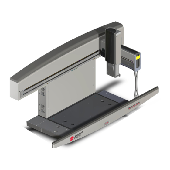
• • Optional Devices Main Components Refer to Figure 1.1 for an example of how a Biomek 4000 can be set up. Figure 1.1 Biomek 4000 Laboratory Automation Workstation 1. Rear Support Assembly 7. Tip Rack Holder 13. Off Deck Platform 2. -
Page 26: Options,
Configuration Options has numerous available configuration options Biomek 4000 Laboratory Automation Workstation and accessories, allowing you to customize your workstation to the specific needs of your laboratory. Table 1.1 shows a configuration matrix of the components that can be installed on your workstation. -
Page 27: Configuration Matrix,
Table 1.1 Biomek 4000 Laboratory Automation Workstation Configuration Matrix Base Instrument Integration Deck Side Module, Left Side Module, Right Mount, Off-Deck, Left Mount, Off-Deck, Right None Integration Deck Side Module, Left Side Module, Right Mount, Off-Deck, Left Mount, Off-Deck, Right... -
Page 28: Instrument,
Introduction System Components Figure 1.2 Biomek 4000 Laboratory Automation Workstation — Base Instrument Item ALP Alternative for Location • Auto-Latch • SPE • Tool Rack 1. Left Side • Manual Latch • SPE Holder • Tool Rack with Gripper Module •... -
Page 29: Instrument With Integration Deck,
Introduction System Components Figure 1.3 Biomek 4000 Laboratory Automation Workstation — Base Instrument With Integration Deck Item ALP Alternative for Location • Orbital Shaker ALP • AutoLatch • SPE Holder • Peltier, Shaking • Disposal ALP • Tool Rack 1. 1 x 1 ALP •... -
Page 30: Assembly,
Introduction System Components Front Rail runs along the front of the workstation. Built into the front rail is an emergency STOP Front Rail button that stops movement of the bridge and pod when pressed. Rear Support Assembly is the rear upright of the instrument that provides the X-axis travel Rear Support Assembly mechanism. -
Page 31: Indicator Lights,
Introduction System Components Bridge is the structure that moves in the X-axis along the rear support and front rail. The bridge Bridge holds the pod and enables movement of the pod in the Y- (front to back) and Z-axis (up and down). Built into the bridge is an indicator light that displays the current operational status of workstation. -
Page 32: Side Modules,
Introduction System Components Side Modules Optional can be added to either the left or right side of the deck to increase the Side Modules available worksurface on the deck. Each module provides additional two deck positions, allowing the deck to be expanded by up to four positions. NOTE Refer to CHAPTER 2, Installing Side... -
Page 33: Tip Rack Holder,
Optional devices can be added to the workstation to accommodate specific operations, such as tip and labware disposal, plate heating and cooling, and microplate filtration. Refer to the Biomek 4000 Laboratory Automation Workstation ALPs and Accessories Manual (PN A99501), Static Peltier ALP Instruction Manual For Biomek 4000 Instruments (PN B20569), and Shaking Peltier ALP Instruction Manual For Biomek 4000 Instruments (PN B20570) for more information about these optional devices. -
Page 34: Circulating Reservoir,
The ALP can be installed to any of the four positions of the integration deck. A maximum of two Shaking Peltier ALPs can be used at one time. Refer to the Shaking Peltier ALP Instruction Manual For Biomek 4000 Instruments (PN B20570) for more information on the Shaking Peltier ALP. -
Page 35: Alp,
The ALP can be installed to any of the four positions of the integration deck. A maximum of two static peltier ALPs can be used at one time. Refer to the Static Peltier ALP Instruction Manual For Biomek 4000 Instruments (PN B20569) for more information on the Static Peltier ALP. - Page 36 Introduction System Components Disposal Accessories The single and double provide a waste receptacle for disposing of tips and Disposal Accessories labware from the deck using the gripper tool. Tip boxes or other labware may be deposited directly to the disposal accessory, eliminating the need to manually dispose of waste. Off-Deck Gripper Tool Rack holds one gripper tool.
-
Page 37: Moving And Installing The Biomek Laboratory Automation Workstation,
Overview Installation of the Biomek 4000 is initially performed by a Laboratory Automation Workstation Beckman Coulter Representative. However, the instrument may need to be relocated after initial installation. Relocating the workstation to a new location includes: • Preparing the site (Preparing the Site). - Page 38 Moving and Installing the Biomek Laboratory Automation Workstation Overview Table 2.1 System Specifications (Continued) Item Description Altitude Restriction up to 2000 m (6562 ft) Installation Category Category II Pollution Degree Communications to AccuFrame and Orbital Shaker Communications to Auto-Latch RS-485 port Communications to Barcode Reader RS-232 port Communications to Biomek Controller...
-
Page 39: Requirements,
Moving and Installing the Biomek Laboratory Automation Workstation Overview Weight and Space Requirements The workstation and all accessories must be installed on a level and stable working surface that can support the workstation and accessories without bowing by more than 1/8 inch. A minimum of 1 foot (0.35 m) of additional space should be available to the left, right, and above the instrument. -
Page 40: Dimensions Required,
• Minimum dimensions required for the work area. • Minimum size and weight load the bench top must support. • Accessory sizes (that extend beyond the envelope of the Biomek 4000 workstation) and weights (for appropriate system weight load). • Location for the Biomek Controller and stand near the instrument bench. -
Page 41: Accessory Dimensions,
Overview Table 2.3 Accessory Dimensions Component Dimensions (approx.) width x depth x height Biomek 4000 Workstation 122.5 x 50.5 x 67.5 48.2 x 19.9 x 26.6 1 x 1 ALP 16.8 x 10.2 x 16.3 6.6 x 4.0 x 6.4 AccuFrame 12.7 x 8.4 x 5.6... -
Page 42: Weights Of Workstation Components,
Table 2.4 to determine the bench load requirements for the approximate installed weight of the workstation. Table 2.4 Weights of Workstation Components Component Weight (approx.) Biomek 4000 Workstation 40.8 1 x 1 ALP Accuframe AccuFrame Deck Adapter AccuFrame Framing Adapter... -
Page 43: Electrical Requirements,
Electrical Requirements CAUTION The Biomek 4000 should be connected to an uninterruptible power source to avoid exposure to an erratic power supply. An erratic power supply could damage the power supply of the instrument or other electrical components. Consult with your local UPS Supplier to determine the proper model for your system. -
Page 44: Moving The Workstation,
CAUTION Two people are needed to lift the Biomek 4000 Laboratory Automation Workstation. Failure to do so could result in bodily injury and/or damage to the workstation. Always lift the workstation by grasping the front rail and bottom of the rear support. -
Page 45: Workstation,
Overview CAUTION Two people are needed to lift the Biomek 4000 Laboratory Automation Workstation. Failure to do so could result in bodily injury and/or damage to the workstation. Always lift the workstation by grasping the front rail and bottom of the rear support. -
Page 46: Connectors,
• AccuFrame Refer to Biomek 4000 Laboratory Automation Workstation ALPs and Accessories Manual (A99501), Static Peltier ALP Instruction Manual For Biomek 4000 Instruments (PN B20569), and Shaking Peltier ALP Instruction Manual For Biomek 4000 Instruments (PN B20570) for more information. - Page 47 Refer to the Biomek 4000 Laboratory Automation Workstation ALPs and Accessories Manual (PN A99501) for more information on the off-deck platform. Install any other devices or accessories, as needed. Refer to the Biomek 4000 Laboratory Automation Workstation ALPs and Accessories Manual (PN A99501), Static Peltier ALP Instruction Manual For Biomek 4000 Instruments (PN B20569), and Shaking Peltier ALP Instruction Manual For Biomek 4000 Instruments (PN B20570) for more information.
-
Page 48: Attaching A Side Module To The Left Side Of The Deck,
Moving and Installing the Biomek Laboratory Automation Workstation Overview Figure 2.4 Attaching a Side Module to the Left Side of the Deck 1. Location Holes 2. Locating Pins Using a 3/16” Allen wrench, secure the side module to the deck with the two large socket-head cap screws. -
Page 49: Fastening The Side Module To The Front Rail,
Moving and Installing the Biomek Laboratory Automation Workstation Overview Figure 2.5 Fastening the Side Module to the Front Rail 1. Small Button-Head Socket Screw 2. Locating Holes Secure the front of the side module to the front rail by fastening a small button-head socket screw through the two locating holes using a 1/8”... -
Page 50: Installing The Spill Tray And Mounting Plate,
Moving and Installing the Biomek Laboratory Automation Workstation Overview Figure 2.6 Installing the Spill Tray and Mounting Plate 1. Mounting Plate 2. Spill Tray 3. Side Module Place the mounting plate on top of the spill tray. If installing side modules on both sides, repeat Steps 1 to 6 to install the other side module. 2-14 A99498AD... -
Page 51: Preventive Maintenance,
Moving and Installing the Biomek Laboratory Automation Workstation Preventive Maintenance Removing Installed Side Modules To remove a side module: Remove the mounting plate and spill tray from the side module (Figure 2.6). Using a 1/8” Allen wrench, remove the small button-head socket screw from the locating holes on the front rail and side module (Figure 2.5). -
Page 52: Cleaning Spill Trays,
WARNING Risk of personal injury. When cleaning spill trays, wear protective gloves and safety goggles if any dangerous chemicals have been used with the Biomek 4000 Laboratory Automation Workstation. Using the large finger grip holes on the deck or side module mounting plate, lift the mounting... - Page 53 Perform the troubleshooting techniques provided in Table 2.6 when necessary. In the case of any other instrument-related problems, contact Table 2.6 Troubleshooting the Biomek 4000 Laboratory Automation Workstation If... Then... All indicator lights are out Verify the instrument is plugged in and turned on.
- Page 54 Moving and Installing the Biomek Laboratory Automation Workstation Troubleshooting the Workstation Table 2.6 Troubleshooting the Biomek 4000 (Continued)Laboratory Automation Workstation If... Then... Tools not picked up by pod Make sure the tool in the tool rack matches the tool expected in the Biomek Software.
-
Page 55: Location Of Fuse Carrier,
Moving and Installing the Biomek Laboratory Automation Workstation Troubleshooting the Workstation Figure 2.8 Location of Fuse Carrier 1. Fuse Holder Cover 2. Power Input 3. Power Switch To change fuses: Turn off power to the workstation. NOTE The power plug serves as the Disconnecting Device and must remain easily accessible. Unplug the power cable from the back of the workstation. -
Page 56: Removing Fuses From Fuse Carrier,
Use the same type of fuses for replacement (see Table 2.7). Spare fuses are shipped in the Biomek 4000 Ship Kit and are available through your local Beckman Coulter Representative. Replace the fuse holder cover on the workstation (Figure 2.8). - Page 57 Refer to the Biomek 4000 Laboratory Automation Workstation ALPs and Accessories Manual (PN A99501) for more information on installing and using the optional off-deck platform on the workstation.
-
Page 58: Holders,
Setting Up the Worksurface Standard Labware Holders Standard Labware Holders Labware holders are used to hold standard and deep-well microplates, 24-position tube racks, and reservoirs on the deck. Each labware holder occupies a single deck position and may hold one piece or stack of labware. -
Page 59: Holder,
Setting Up the Worksurface Standard Labware Holders Figure 3.1 Installing Labware Holder on the Deck 1. Front Label 2. Locating Pins-Not visible, on bottom of labware positioner. 3. Locating Holes Firmly press down on the labware holder until it clicks into position to secure the labware holder to the deck. - Page 60 Setting Up the Worksurface Standard Labware Holders Removing Labware Holders from the Worksurface Labware holders may be removed from the deck to accommodate other labware positioners. To remove a labware holder from the deck: Remove any labware in the labware holder. Carefully but firmly lift the labware holder straight up so that the locating pins are completely removed from the predrilled locating holes on the deck.
-
Page 61: Tip Rack Holders,
There are two types of tip rack holders available for use on the workstation: • Manual Tip Rack Holder ( ManualLatch Deck Editor • Auto-Latching Tip Rack Holder ( - refer to the Biomek 4000 Laboratory AutoLatch Deck Editor Automation Workstation ALPs and Accessories Manual (PN A99501) for more information) NOTE When adding the tip rack holder to the Deck Editor in Biomek Software, be sure to add the correct type, as indicated above. - Page 62 Setting Up the Worksurface Tip Rack Holders Inserting Tip Racks into Manual Tip Rack Holders Tip boxes must be inserted into a manual tip rack holder correctly for pipette tools to be able to load and unload tips. To insert a tip rack into a manual tip rack holder: Push the sliding latch on the bottom left of the tip rack holder from right to left.
- Page 63 Setting Up the Worksurface Tip Rack Holders Removing Manual Tip Rack Holders from the Worksurface Manual tip rack holders may be removed from the deck to accommodate other labware positioners. To remove a manual tip rack holder from the deck: Remove the tip box from the manual tip rack holder.
-
Page 64: Racks,
For the off-deck platform, off-deck tool racks can hold up to two tools. The off-deck gripper tool rack for this platform holds one gripper tool (Figure 3.3). Refer to the Biomek 4000 Laboratory Automation Workstation ALPs and Accessories Manual (PN A99501) for additional information on the off-deck platform. -
Page 65: Installing Tool Racks,
Setting Up the Worksurface Tool Racks and Gripper Tool Racks Installing Tool Racks A tool rack can be installed on any position on the deck or side module. NOTE After physically installing the tool rack or gripper tool rack, it must be placed on the deck in the Deck (refer to the Biomek Software User's Manual Version 4.1 (PN B30026) or the Biomek Software Editor... -
Page 66: Framing Instructions,
Setting Up the Worksurface Tool Racks and Gripper Tool Racks Framing Instructions Tool racks must be framed so the workstation pod can accurately position itself above the tool rack to load and unload tools. Because of the size and shape of the tool rack, it is necessary to frame the tool rack position using a standard labware holder in the desired position. - Page 67 NOTE Refer to the Biomek 4000 Laboratory Automation Workstation ALPs and Accessories Manual (PN A99501) for more information on the vacuum manifold filtration system. NOTE When not holding a vacuum manifold collar, the collar holder may be used as a standard labware holder.
- Page 68 Setting Up the Worksurface Collar Holder Figure 3.5 Installing Collar Holder on the Deck 1. Locating Holes 2. Locating Pins Firmly press down on the collar holder until it clicks into position to secure the collar holder to the deck. Framing Instructions Frame collar holders using the position target according to the instructions in CHAPTER 7, Manually...
-
Page 69: Worksurface,
Setting Up the Worksurface Collar Holder Figure 3.6 Installing Collar on Collar Holder 1. Collar 2. Holding Pins Removing Collar Holders from the Worksurface Collar holders may be removed from the deck to accommodate other labware positioners. To remove a labware holder from the deck: Remove any installed collar or labware from the collar holder. - Page 70 Setting Up the Worksurface Collar Holder Storing Collar Holders Return collar holders to their original packing materials and store in a dry, dust-free, environmentally-controlled area when not in use. NOTE It is desirable to allow the collar holders to air-dry before returning them to the original packing materials.
- Page 71 CHAPTER 4 Pipetting Tools Overview A variety of single-channel and multi-channel pipetting tools are available to perform liquid aspirate and dispense actions from a single well or eight wells simultaneously. Each tool is designed to optimize pipetting operations for specific volume ranges. Pipette tools can be used for liquid transfers from plate-to-plate, tube-to-plate, or tube-to-tube.
-
Page 72: Pipetting Tools,
Pipetting Tools Overview Figure 4.1 shows a MP200 eight-channel tool Figure 4.1 MP200 Eight-Channel Tool 1. Holding Pins 2. Front Label 3. Connector ID Pins IMPORTANT The Connector ID Pins are fragile. Use care when handling the pins. NOTE Pipette tools must be added and configured in and placed on a tool rack in an Hardware Setup step (refer to the Biomek Software User's Manual Version 4.1 (PN B30026) or the... -
Page 73: Liquid Level Sensing,
Pipetting Tools Installing Pipette Tools on the Tool Racks that bounces back when it contacts liquid. The receiver detects the wave as it bounces back past the end of the tip. NOTE For best results with liquid level sensing, it is recommended to use P250 tips on the P200L Single-Tip Pipette Tool, or P1000 Span-8 tips on the P1000SL Single-Tip Pipette Tool. - Page 74 Pipetting Tools Installing Pipette Tools on the Tool Racks Figure 4.2 Installing Pipette Tools into Tool Rack 1. Holding Pins (One on opposite 2. Front Label side not shown.) A99498AD...
- Page 75 Pipetting Tools Tip Compatibility Tip Compatibility Interchangeable pipette tools installed on the pod aspirate and dispense liquid using disposable tips. The compatible tip types and the volumes that may be aspirated and dispensed with those tip types varies for each tool type, as described in Table 4.1.
-
Page 76: Tip Compatibility,
Pipetting Tools Tip Compatibility Table 4.2 Labware and Tool/Tip Compatibility Tool Tip Type Labware Type Modular Reservoir Flat Deep Flat Deep 10 mm 12 mm 13 mm 15 mm Microfuge Tubes Tubes Tubes Tubes P250 P200L P250 P1000SL P1000 P1000 Wide Bore MP20 P250... - Page 77 Pipetting Tools Storing Pipette Tools Storing Pipette Tools Return the pipette tool(s) to the original packing materials and store in a dry, dust-free, environmentally controlled area when not in use. NOTE It is desirable to allow the pipette tool(s) to air-dry before returning to the original packing materials. Preventive Maintenance WARNING Risk of personal injury.
- Page 78 Pipetting Tools Troubleshooting Pipette Tools Troubleshooting Pipette Tools Do not attempt to repair the pipette tools without first contacting your Beckman Coulter Representative. If experiencing problems with a pipette tool, consult Table 4.3. Table 4.3 Troubleshooting Pipette Tools If... Then...
-
Page 79: Tools,
Make sure liquid level sensing tool is being used and LLS is enabled. Make sure tips are compatible with LLS (non-barrier tips). Contact Clogged tip Use new Beckman Coulter tips when liquid level sensing. Make sure appropriate tip type is being used. NOTE Barrier tips cannot be used for liquid level sensing. - Page 80 Pipetting Tools Troubleshooting Pipette Tools 4-10 A99498AD...
-
Page 81: Gripper Tool,
Overview is a specialized tool that, when loaded onto the Gripper Tool Biomek 4000 Laboratory Automation pod, allows the workstation to grasp and move labware around the deck. Workstation The gripper tool has two finger pads in front and one finger pad in back for grasping labware or stacks of labware securely. -
Page 82: Installing Gripper Tool In Gripper Tool Rack,
NOTE Make sure the label and arrow point toward the front of the Biomek 4000 workstation. FRONT NOTE The tool rack is keyed so that the gripper tool only fits in the correct orientation. - Page 83 Gripper Tool Removing the Gripper Tool from the Tool Rack Removing the Gripper Tool from the Tool Rack CAUTION Bending the tool ID or alignment pins that are along the top of the gripper tool may cause them to break off or become damaged. Take care not to bend the tool ID or alignment pins.
-
Page 84: Tool,
• To ensure proper gripping of labware, replace finger pads on a regular basis (refer to Replacing Gripper Finger Pads). Troubleshooting the Gripper Tool IMPORTANT Do not attempt to repair the gripper tool without first contacting your Beckman Coulter Representative. If experiencing problems with a gripper tool consult Table 5.1. -
Page 85: Replacing Finger Pad On The Rear Finger Assembly,
Gripper Tool Troubleshooting the Gripper Tool Use a single-edged razor blade to carefully slit the finger pads on both sides and remove them from the pad supports. Scrape the pad/adhesive residue from the pad supports using a razor, and then wipe the support pads clean with the an emory cloth or soft tissue. -
Page 86: Replacing Finger Pads On The Front Finger Assembly,
Gripper Tool Troubleshooting the Gripper Tool WARNING Risk of personal injury. The adhesive used when replacing gripper finger pads has a short set-up time and has a very strong bonding agent. Do not get any adhesive on your fingers. Carefully wipe any excess adhesive from the outside surfaces of the pad with a soft tissue. Repeat Steps 5-9 to bond the other two finger pads to the pad support. -
Page 87: Hardware Setup,
This connection is established by installing, configuring, and removing devices in Hardware Setup Once a device has been physically installed, the device is detected on the Biomek 4000 Laboratory and must be properly installed and configured in . -
Page 88: Hardware Setup For Biomek 4000 Laboratory Automation Workstation,
To access Hardware Setup Select appears. Start All Programs Beckman Coulter Biomek Software Biomek Software > > > From the menu, select appears (Figure 6.1). Instrument Hardware Setup Hardware Setup Figure 6.1 Hardware Setup for Biomek 4000 Laboratory Automation Workstation A99498AD... -
Page 89: Configuring The Workstation,
Biomek 4000 Laboratory Automation Workstation In Biomek Software, select from the menu. appears. Hardware Setup Instrument Hardware Setup Select Biomek 4000 from the left pane of . The configuration view appears in the Hardware Setup right pane (Figure 6.1). A99498AD... -
Page 90: Hardware Setup Showing The Configuration View For A Pod,
Hardware Setup Configuring the Workstation Ensure the serial number listed in corresponds to the serial number on the Hardware Setup workstation. , select the serial communications port on the Biomek Controller that is connected to the Port workstation. In the left pane of , select to display the pod configuration (Figure... -
Page 91: Troubleshooting Homing Instrument Cautions,
Most of the properties, including pod settings and axis limits, of a Biomek 4000 Laboratory Pod are initially configured by a Beckman Coulter Representative in Automation Workstation and should not be modified without specific instructions from your Beckman Coulter Hardware Setup Representative. NOTE Some of the fields listed in Table 6.3... -
Page 92: Device Has Been Modified,
However, other devices may be configured when the workstation is configured, and may be chosen after all devices have been configured. Accept Table 6.3 Biomek 4000 Laboratory Automation Workstation Pod Properties Property Description Additional Roving Height Margin above the default height for the pod as it moves over everything on the deck. -
Page 93: Settings,
Hardware Setup Configuring the Workstation Calibrating the X- and Y-Axis The drive cables of the workstation stretch and change over time. These changes in the drive cables can cause the movements estimated by Biomek Software to position the pod in a desired location to require slight corrections. -
Page 94: Save Configuration,
Hardware Setup Configuring the Workstation Figure 6.5 Save Configuration , enter a name for the settings. Name If desired, enter a of the configuration. Description Click . The settings are saved. A99498AD... - Page 95 Hardware Setup Configuring the Workstation Restoring Pod Settings To load the saved settings: , select from the left pane to access the configuration area in the right Hardware Setup Pod 1 pane. Click appears (Figure 6.6). Restore Settings Load Settings Figure 6.6 Load Settings Click .
- Page 96 Hardware Setup Configuring the Workstation Deleting Pod Settings To delete settings: , select the from the left pane to access the configuration area in the Hardware Setup Pod 1 right pane. Select appear (Figure 6.8). Delete Settings Delete Settings Figure 6.8 Delete Settings Click .
-
Page 97: Devices,
Hardware Setup Adding and Removing Tools and Devices Adding and Removing Tools and Devices Any accessories used with the instrument — devices that use an RS-485 communications link to the workstation, such as an or other external device — must be added in Auto-Latch Controller Hardware . -
Page 98: Adding A Device,
Hardware Setup Adding and Removing Tools and Devices Figure 6.10 Adding a Device Select the desired tool or device. The tool or device is added to the list of installed tools or devices in the appropriate category in the left pane. Select from the top of displays all tools, CAN, RS-485... -
Page 99: New Devices Displaying All Tools, Can Devices, Rs-485 Devices And External Devices,
Configure the installed tool or device: • CAN and RS-485 devices require no additional configuration, except for the wash system. Refer to the Biomek 4000 Laboratory Automation Workstation ALPs and Accessories Manual (PN A99501) for more information. • Refer to Configuring Tools, for information on configuring tools. -
Page 100: Configuring Tools,
Hardware Setup Configuring Tools Removing Tools and Devices If a tool or device is no longer used with the workstation, it should be removed from Hardware . A tool or device that has been removed from may not be used in Biomek Setup Hardware Setup Software. -
Page 101: Hardware Setup Configuration For A Pipetting Tool,
Beckman Coulter Representative in Tool Unload Z Offset Hardware Setup and should not be modified without specific instructions from your Beckman Coulter Representative. displays the conversion factor for the tool between microliters dispensed Tool Conversion Slope and centimeters of movement by the tool plunger in the D-axis (μL/cm). -
Page 102: Tip Loading Troubleshooting,
Beckman Coulter Representative in Tip Load Settling Time Hardware Setup and should not be modified without specific instructions from your Beckman Coulter Representative. , displays the position along the D-axis the pod returns to after unloading Tip Unload D Position tips from the tool. - Page 103 Hardware Setup Configuring Tools Click . Hardware Setup closes. Accept NOTE must be chosen after the instrument has been configured to allow Accept Hardware Setup accept the configurations. However, other devices may be configured when the workstation is configured, and may be chosen after all devices have been configured.
- Page 104 NOTE is configured by a Beckman Coulter Representative in Tool Unload Z Offset Hardware Setup and should not be modified without specific instructions from your Beckman Coulter Representative. Make sure the box is enabled (i.e., checked). Enable Plate Sensor Frame the gripper tool and calibrate the sensor according to the procedure described in CHAPTER 7, Manually Framing Deck Positions.
- Page 105 Beckman Coulter Representative in Tool Unload Z Offset Hardware Setup and should not be modified without specific instructions from your Beckman Coulter Representative. , display the number of motors steps per μL for the wash Calibration Slope Calibration Offset system.
- Page 106 Hardware Setup Configuring External Devices Click closes. Accept Hardware Setup NOTE must be chosen after the instrument has been configured to allow Accept Hardware Setup accept the configurations. However, other devices may be configured when the workstation is configured and may be chosen after all devices have been configured.
- Page 107 Hardware Setup Configuring External Devices Click closes. Accept Hardware Setup NOTE must be chosen after the instrument has been configured to allow Accept Hardware Setup accept the configurations. However, other devices may be configured when the workstation is configured and may be chosen after all devices have been configured.
- Page 108 Hardware Setup Configuring External Devices 6-22 A99498AD...
-
Page 109: Framing,
WARNING The Biomek 4000 instrument should be reframed following a crash. Failure to reframe the instrument can result in additional crashes. A Beckman Coulter Representative frames the workstation during system installation. It may be necessary to repeat the framing if: •... -
Page 110: Installing The Framing Tool On The Pod,
Framing Attaching the Manual Framing Tool Attaching the Manual Framing Tool To manually frame the workstation requires installing the framing tool on the pod. The framing tool is a tool with a single probe used to precisely teach the Biomek Software the locations of all labware positioners on the deck. -
Page 111: Deck Editor For Biomek 4000 Laboratory Automation Workstation,
Manual Teach Select to open the Biomek Software. Start All Programs Beckman Coulter Biomek > > > From the menu, select appears (Figure 7.2). Instrument Deck Editor Deck Editor Figure 7.2 Deck Editor for Biomek 4000 Laboratory Automation Workstation A99498AD... -
Page 112: Position Properties For A Labware Positioner,
(Figure 7.3). Position Properties Figure 7.3 Position Properties for a Labware Positioner , verify that the position is assigned a unique name. Name Select . Biomek 4000 opens with a warning (Figure 7.4). Manual Teach Manual Framing Wizard NOTE On the left side of... -
Page 113: Framing Adapter Is Not Required,
Framing Manually Framing Deck Positions Address the warning, then click to continue. The Next Adapter appears NOTE The appearance of depends on the type of position being framed. If no framing adapter Adapter is required to frame the position, Figure 7.5 appears. -
Page 114: Loading Tool During Manual Teach,
Framing Manually Framing Deck Positions Figure 7.7 Loading Tool During Manual Teach If necessary, install the framing tool and tip onto the pod (refer to Attaching the Manual Framing Tool). Select the type of tip loaded on the framing tool from the drop-down box in Load the tip of type Click Next to continue. -
Page 115: Teaching Instructions,
Teach Z • Refer to Framing the Z-Axis. The pod moves up to its maximum height in the Z-axis, closes, Biomek 4000 Manual Teaching appears. Teaching Instructions Figure 7.9 Teaching Instructions Select from , or for the appropriate teaching instructions. -
Page 116: Target,
Properties Click to save the framing information and close Position Properties Repeat the procedure to frame additional deck positions using Biomek 4000 Manual Teach Click to save framing information for all positions and close the (Figure 7.2). Save... -
Page 117: Wells,
Since tip height is set in the next step in the process, it is safe to move Biomek 4000 Manual Teach the pod to any height to make aligning the tips with the target position easier. Adjust the position of the tip to align it with the target position by either: •... -
Page 118: Framing To The Corner Of Four Wells,
Z-axis until it is approximately 1 mm above the top of the microplate. NOTE Since tip height is set in the next step in the Biomek 4000 process, it is safe to move Manual Teach the pod to any height to make aligning the tips with the target position easier. - Page 119 Framing Manually Framing Deck Positions Using the Graphic Alignment Tool The graphic alignment tool (Figure 7.13) is used to instruct the Biomek Software of the current position of the framing tool tip to the target position on the labware positioner or microplate. The Biomek Software uses the information it is given to move the pod so the framing tool tip is directly above the target position.
-
Page 120: Buttons,
The tip may also be aligned with the position using the delta value and directional buttons (refer Using the Delta Value and Directional Buttons). Once the tip is aligned with the target position on the labware positioner or microplate, click to continue. Biomek 4000 displays (refer to Framing the Z-Axis). - Page 121 The tip may also be aligned with the position using the graphic alignment tool (refer to Using the Graphic Alignment Tool). Once the tip is aligned with the target position on the labware positioner or microplate, click to continue. Biomek 4000 displays (refer to Framing the Z-Axis).
-
Page 122: Manual Teaching The Z-Axis,
Framing Manually Framing Deck Positions Framing the Z-Axis After the X- and Y-axis are framed, the Z-axis must be framed to ensure aspirate and dispense operations are performed at the desired height (Figure 7.15). Figure 7.15 Manual Teaching the Z-Axis , select the magnitude of change applied to the framing tool tip each time a directional Delta button is selected... - Page 123 Framing Manually Framing Deck Positions Select the representing the motion required to physically move the tip down directional button until the tip just touches the top of the feeler gauge or the bottom of the well. NOTE Each time a directional button is selected, the pod and tips move the distance specified in Delta in the indicated direction.
- Page 124 Framing Attaching the Framing Adapter to the Manual Framing Tool Attaching the Framing Adapter to the Manual Framing Tool To frame the workstation with the requires installing the framing tool and framing AccuFrame adapter on the pod. The framing tool is a tool with a single probe used to precisely teach the Biomek Software the locations of all labware positioners on the deck.
-
Page 125: Installing The Accuframe,
Some labware positioners need a deck adapter to use the AccuFrame. The positioners are the Manual Tip Rack Holder and Auto-latching Tip Rack Holder. Refer to the Biomek 4000 Laboratory Automation Workstation ALPs and Accessories Manual (PN A99501) for more information on the Auto- latching Tip Rack Holder. -
Page 126: Installing The Deck Adapter,
Framing Installing the Deck Adapter Figure 7.17 Installing the Deck Adapter 1. AccuFrame 2. Deck Adapter 3. Manual Tip Rack Holder Open the sliding latch on the manual tip rack holder. Firmly position the deck adapter in the tip rack holder. NOTE Ensure that the arrow marked is pointing toward the front of the deck. -
Page 127: Deck,
Auto Teach Select to open the Biomek Software. Start All Programs Beckman Coulter Biomek > > > From the menu, select appears (Figure 7.18) Instrument Deck Editor Deck Editor Figure 7.18 Deck Editor for Biomek 4000 Laboratory Automation Workstation 7-19 A99498AD... - Page 128 Framing Installing the AccuFrame on the Deck Double-click on the deck position to open for the desired deck positions Position Properties (Figure 7.19). Figure 7.19 Position Properties for a Labware Positioner Select . The pod moves to the position that is being taught. The framing tool should Auto Teach be above the AccuFrame in that position.
- Page 129 Framing Installing the AccuFrame on the Deck If necessary, address the warning, then click to continue. • The pod lowers and automatically moves around within the AccuFrame until it breaks both light beams. The pod stops after framing has completed, and the two light beam indicators are illuminated.
-
Page 130: Framing Troubleshooting,
After all positions have been framed, remove the framing tool by pressing the tool release button. WARNING Turn off power to the Biomek 4000 Laboratory Automation Workstation before attaching or removing AccuFrame. Failure to do so can cause electrical shock or equipment damage. - Page 131 The gripper tool is framed using the framing plate. A Beckman Coulter Representative frames the gripper tool during system installation; however, it may be necessary to repeat the framing procedure if: •...
-
Page 132: Hardware Setup For Gripper Tool,
Framing Framing the Gripper Tool Under in the left pane, select the desired gripper tool to frame. The Tools Configuration to Frame appears on the right (Figure 7.22). the Grippers Figure 7.22 Hardware Setup for Gripper Tool Select . The following warning appears (Figure 7.23): Frame Gripper... -
Page 133: Pick Previously Framed Deck Position To Frame The Gripper Tool,
Framing Framing the Gripper Tool Address the warning appropriately and click to continue. appears (Figure 7.24). Pick Position Figure 7.24 Pick Previously Framed Deck Position to Frame the Gripper Tool , select a previously framed deck position and frame the gripper tool to that Pick Position location. - Page 134 Framing Framing the Gripper Tool Click . The pod moves to the selected position and extends the gripper tool. Manual Control (Figure 7.26) and (Figure 7.27) appear side by side. Frame Gripper NOTE The gripper tools are extended a little high and opened a little wide at the end of the move initiated by Step 9.
-
Page 135: Sensor,
Before calibrating the sensor, make sure the gripper tool has been properly framed (refer to Framing the Gripper Tool). To calibrate the gripper sensor: Select to start the Biomek Software. Start All Programs Beckman Coulter Biomek > > > 7-27 A99498AD... -
Page 136: Grippers Warning,
Framing Framing the Gripper Tool From the menu, select appears. Instrument Hardware Setup Hardware Setup Under in the left pane, select the desired gripper tool to frame. The Tools Configuration to Frame screen appears on the right (Figure 7.29). the Grippers Figure 7.29 Hardware Setup for Gripper Tool Select . -
Page 137: Pick Previously Framed Deck Position To Calibrate Gripper Sensor,
Framing Framing the Gripper Tool If necessary, address the warning, then click to continue. appears (Figure 7.31). Pick Position Figure 7.31 Pick Previously framed Deck Position to Calibrate Gripper Sensor , select a previously framed deck position. Pick Position Place the gripper tool framing plate on the deck position selected in . -
Page 138: Accuracy,
Framing Framing the Gripper Tool Click to confirm that the gripper tool is holding the framing plate. The gripper tool unsqueezes by one unit and the message appears again. Confirm Click if the gripper tool is no longer holding the framing plate. NOTE If the gripper does not pick up the framing plate, reframe the gripper. -
Page 139: Control,
An information dialog Manual Control Manual Control Instrument appears briefly as the connection is made with the Biomek 4000 Laboratory Automation Workstation immediately followed by (Figure 8.1). Manual Control NOTE is available only when a method is not being executed. If manual control is necessary... -
Page 140: Version,
Manually Controlling the Workstation Using Manual Control Using Manual Control Manual Control • Homing all Axis of the Pod Moving the Pod to a Specific Deck Position • • Stopping a Pod • Viewing the Firmware Version Accessing Advanced Manual Control •... -
Page 141: Pod,
Manually Controlling the Workstation Using Manual Control Figure 8.2 Homing Instrument Warning Table 8.1 Troubleshooting Homing Instrument Cautions Ensure Otherwise No liquid is present in the tips. Liquid will eject from the tip as part of the homing operation at an arbitrary location on the deck. -
Page 142: Height,
Manually Controlling the Workstation Using Manual Control Stopping a Pod To stop a pod once a movement has started: From the menu, select appears (Figure 8.1). Instrument Manual Control Manual Control Select . The pod stops its movement. Viewing the Firmware Version shows the current firmware version for the workstation and any installed devices. - Page 143 Manually Controlling the Workstation Using Manual Control Accessing Advanced Manual Control To access Advanced Manual Control From the menu, select appears (Figure 8.1). Instrument Manual Control Manual Control Select Select a device from the menu. for the selected device appears. Advanced Manual Control A99498AD...
-
Page 144: Performing Absolute Moves Of The Pod
Manually Controlling the Workstation Using Advanced Manual Control with the Pod Using Advanced Manual Control with the Pod for the pod for: Advanced Manual Control • Viewing the Current Position of the Pod Moving the Pod to a Safe Roving Height •... - Page 145 Manually Controlling the Workstation Using Advanced Manual Control with the Pod Table 8.2 Advanced Manual Control Selection Areas for the Pod Area Description Absolute Move Builds a vector to an absolute coordinate from the current coordinate. Auto Clear When checked, the Movement Vector resets to the 0 vector (no movement) each time Go is selected.
- Page 146 Manually Controlling the Workstation Using Advanced Manual Control with the Pod Select for the pod appears (Figure 8.4). The current position is Pod1 Advanced Manual Control shown in Current Position Click to close Close Advanced Manual Control Click to close Exit Manual Control Moving the Pod to a Safe Roving Height...
- Page 147 Manually Controlling the Workstation Using Advanced Manual Control with the Pod Performing Relative Moves Using the Vector Builder The use of for the pod centers around the building and applying of Advanced Manual Control movement vectors. A movement vector simply indicates the magnitude and direction of motion applied to the pod.
- Page 148 Manually Controlling the Workstation Using Advanced Manual Control with the Pod Enter the desired , and values in Movement Vector Click the appropriate buttons in (Figure 8.5) until the desired values appear in Vector Builder (Figure 8.4). The , or value in changes by the Movement Vector...
- Page 149 Manually Controlling the Workstation Using Advanced Manual Control with the Pod Performing Absolute Moves of the Pod allows the pod to move to a specific coordinate position in the workspace of the Absolute Move instrument. Use when the coordinates of the desired position are known. Absolute Move NOTE When an...
- Page 150 Manually Controlling the Workstation Using Advanced Manual Control with the Pod Click . The pod moves from its current position to a specified absolute position. The new position is displayed in Current Position Click to close Close Advanced Manual Control Click to close Exit...
-
Page 151: Terms And Definitions
Auto-Latching Tip Rack Holder — Provides precise positioning of tip racks on the deck during an automated method. Axis — Direction along which movement can occur. Biomek 4000 has four axis (X-, Y-, Z-, and D- [T-]). Barcode Reader — Device that scans barcode labels applied to labware. Can be mounted to the right or left side module. - Page 152 Since it is a hand-held reader, it can scan anything with a compatible bar code on any surface. Head Assembly — Known as the Pod on the Biomek 4000 Laboratory Automation Workstation, and is referred to as Pod1 in the Biomek Software. Used for tool loading/unloading, liquid-handling, and labware manipulation.
- Page 153 Labware Properties — Characteristics of labware for use in a method. Accessed from either Device Setup or Instrument Setup steps. Liquid Level Sensing — On the Biomek 4000, P200L and P1000SL tools include patented technology that sonically detects the liquid level. Liquid level sensing is performed using an acoustic process involving a transmitter and receiver within the single-channel tools.
- Page 154 Teaching — Process of providing exact coordinates of positions on the Biomek deck or exact offsets for grippers. Also called framing. Thermal Exchange Unit — Heats or cools a reservoir or microplate on the Biomek 4000 deck. The temperature is controlled by a user-supplied circulating bath.
- Page 155 Abbreviations % — percent in. — inch °C — degrees Celsius kg — kilogram °F — degrees Fahrenheit lbs — pounds ALP — Automated Labware Positioner LCD — liquid crystal display ANSI — American National Standards Institute LED — light-emitting diode cm —...
- Page 156 Abbreviations Abbreviations-2 A99498AD...
- Page 157 Biomek 4000 vacuum requirements, Move Z-Max, weight and space requirements, performing absolute moves, 8-11 troubleshooting, 2-17 performing relative moves, Biomek 4000 Overview, defined, bridge selection areas for Multichannel Pod, defined, axes indicator lights, homing, China RoHS Caution Label, 1-xi...
- Page 158 Index using in Manual Teach, 7-12 storing, devices troubleshooting, adding in Hardware Setup, 6-11 configuring in Hardware Setup, 6-20 optional Hardware Setup, overview, 1-11 accessing, removing from Hardware Setup, 6-14 adding devices, 6-11 disposal accessory adding tools, 6-11 defined, 1-14 configuring devices, 6-20 configuring gripper tool,...
- Page 159 7-11 using in Hardware Setup, manual tip rack holders Relative Move defined, movement values defined, inserting tip racks, performing with Biomek 4000, installing, using in Advanced Manual Control, preventive maintenance, RS-485 devices removing from deck, adding in Hardware Setup, 6-11...
- Page 160 Index storing, tool racks safe roving height defined, 1-11, move Biomek 4000 to, framing, 3-10 safety notice installing, chemical and biological safety, 1-viii installing gripper tool, 5-1, cleaning, installing pipette tools, electrical safety, 1-vii preventive maintenance, 3-11 instrument safety precautions,...
- Page 161 Beckman Coulter, Inc. Warranty and Returned Goods Requirements All standard Beckman Coulter, Inc. policies governing returned goods apply to this product. Subject to the exceptions and upon the conditions stated below, the Company warrants that the products sold under this sales agreement shall be free from defects in workmanship and materials for one...
- Page 162 Performance characteristics and specifications are only warranted when Beckman Coulter replacement parts are used. Except as provided in writing signed by an officer to Beckman Coulter, Inc., this system and any related documentation are provided “as is” without warranty of any kind, expressed or implied, including that the system is “error free.”...
-
Page 164: Related Documents
Biomek Software User’s PN B20570 Biomek 4000 Laboratory Manual Version 4.2 Automation Workstation PN C40390 Static Peltier ALP Instruction ALPs and Accessories Manual Manual for Biomek 4000 PN A99501 Instruments PN B20569 Biomek 4000 Laboratory Automation Workstation Software Tutorial PN A99502 www.beckman.com...
Need help?
Do you have a question about the Biomek 4000 and is the answer not in the manual?
Questions and answers