Table of Contents
Advertisement
Advertisement
Table of Contents

Related Manuals for Bongshin BS-3520


Summary of Contents for Bongshin BS-3520
- Page 1 BS-3520 Digital Indicator The Better Way for Weighing & Measurements...
-
Page 2: Table Of Contents
Table of Contents 1. Introduction.............................3 1-1 Trait ..............................3 1-2 Warning ............................. 4 2. Specification............................5 3. External Size............................6 4. Description on Front Panel…......................7 5. Description on Rear Panel........................9 5-1 Description on Each Terminal Unit...................... 9 5-2 How to Use Terminal Block and Replace Fuse...................12 6. - Page 3 10. Analog Output..........................45 10-1 Analog Output Mode ........................45 10-2 Analog Output Specification and Connection Method..............46 10-3 Analog Output Zero and Span Calibration..................47 10-4 Analog Output Zero and Span Minute Calibration................49 11. BCD Output.............................51 11-1 BCD Parallel Output ......................... 51 ...
-
Page 4: Introduction
All functions can sufficiently be utilized if you thoroughly read the manual before use. 1-1 Features BS-3520 is high precision high speed indicator of 96x96mm size. ■ High precision 24bit Sigma-Delta A/D converter ■ High speed A/D and D/A conversion of 2000 time/sec ■... -
Page 5: Warning
1-2 Warning ■ Check whether or not there was damage in product during the delivery. ■ Do not drop or exert server impact on the product. ■ Front panel control button is operated with light touch thus do not exert excessive strength. Do not use or store product at location with severe temperature change if possible. -
Page 6: Specification
2. Specification Load Cell excitation DC 5V, 60mA ( 350Ω x 4 load cells can be connected ) Min. Input Sensitivity 0.2μV /Digit (min.) Non-linearity 0.01% F.S. max. Analog Input Signal Range -34 mV ~ +34 mV Zero: ±0.1μV/ °C RTI max. Temperature drift SPAN: 10ppm/°C max. -
Page 7: External Size
3. External Size - 3520 DIGITAL INDICATOR HOLD ZERO HIGH AC85~AC240V 48Hz~63Hz CURR VOLT PANEL CUT 9 10 11 12 LOAD CELL INPUT OUTPUT PANEL GUIDE ... -
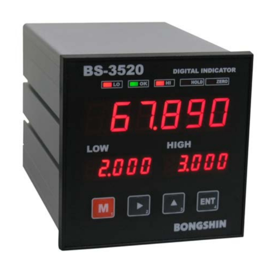
Page 8: Description On Front Panel
4. Description on Front Panel - 3520 DIGITAL INDICATOR Status Lamp HOLD ZERO Weight Value Display HIGH Low Display High Display Key Switch Display of measurement data and setting value is conducted. Weight Value Display Setting of decimal point is conducted at function mode. - Page 9 Key Switch It is used when entering user setting mode from measurement mode. It is used when exiting to measurement mode from user setting mode. (ESC function) It is used as location shift key when entering numerical value of user setting mode. It is used as calibration mode entry key It is used as check mode entry key It is used as a key to increase and decrease the numerical value of selected...
-
Page 10: Description On Rear Panel
5. Description on Rear Panel Power AC85~AC240V 48Hz~63Hz Grounding Serial Output CURR VOLT Option Load Cell Input/Output Connection 9 10 11 12 LOAD CELL INPUT OUTPUT ... - Page 11 5-1-2 LOAD CELL Connection (1) (2) (3) (4) (5) Name Contents Terminal No. EXC + Load Cell Voltage (+), Red wire EXC - Load Cell Voltage (-), White wire SIG + Load Cell Input Voltage (+), Green wire SIG - Load Cell Input Voltage (-), Blue wire SHIELD Load Cell Grounding...
- Page 12 5-1-3 Input (6) (7) (8) Terminal No. Name Contents Control terminal of zero function ZERO Valid from COM1 terminal and short circuit (or on coin) Control terminal of hold function HOLD Valid from COM1 terminal and short circuit (or on coin) COM1 Common terminal of external control ...
-
Page 13: How To Use Terminal Block And Replace Fuse
5-2 How to Use Terminal Block and Replace Fuse 5-2-1 How to use terminal block 1) Peel off the sheath at the end of cable. 2) Terminal is opened when putting driver inside the terminal opening device (top of terminal) and push upward. 3) Terminal is fastened when inserting the cable and pulls back the driver. -
Page 14: Calibration
6. CALIBRATION There are 3 types of calibration mode. 6-1 Calibration Mode 6-1-1 Mode ■ Digital calibration mode Calibration shall be conducted not by using the actual load but entering rated output and rated capacity of sensor with key. -
Page 15: Digital Calibration Mode
6-2 Digital calibration mode 6-2-1 Calibration Method Step 1. Decimal point setting and min. gradation setting - 3520 - 3520 - 3520 DIGITAL INDICATOR DIGITAL INDICATOR DIGITAL INDICATOR HOLD ZERO HOLD ZERO HOLD ZERO HIGH HIGH HIGH When you push No.3 key while It is changed to decimal point Push No.4 key by changing pushing No.1 key, entry to... - Page 16 - 3520 - 3520 - 3520 DIGITAL INDICATOR DIGITAL INDICATOR DIGITAL INDICATOR HOLD ZERO HOLD ZERO HOLD ZERO HIGH HIGH HIGH Input load cell rated output Input rated capacity of load cell Digital input is completed when using No. 2 and No.3 key and with the use of No.2 and No,.3 pushing No.4 key and it returns Push No.4 key.
-
Page 17: Actual Load Calibration Mode
6-3 Actual load calibration mode 6-3-1 Calibration Method Step 1. Decimal point setting and min. gradation setting - 3520 - 3520 - 3520 DIGITAL INDICATOR DIGITAL INDICATOR DIGITAL INDICATOR HOLD ZERO HOLD ZERO HOLD ZERO HIGH HIGH HIGH Entry to function mode is It changes to decimal point Push No. - Page 18 - 3520 - 3520 - 3520 DIGITAL INDICATOR DIGITAL INDICATOR DIGITAL INDICATOR HOLD ZERO HOLD ZERO HOLD ZERO HIGH HIGH HIGH Select Unload among Load and Unload with the use of No.2 It is changed to dead weight and No.3 key and push No.4 Conduct zero calibration.
-
Page 19: Linearization Calibration Mode
6-4 Linearization Calibration Mode 6-4-1 Calibration Method A little measurement error may occur in between the max capacity due to trait of measurement unit even upon the completion of zero and span calibration. Linearization calibration mode is a type of calibration mode which conducts non-linear calibration that reduces the measurement error by conducting calibration with max 4 points excluding the zero with the use of actual load. - Page 20 Step 2. Zero calibration and dead weight setting - 3520 - 3520 - 3520 DIGITAL INDICATOR DIGITAL INDICATOR DIGITAL INDICATOR HOLD ZERO HOLD ZERO HOLD ZERO HIGH HIGH HIGH Push No.2 key while pushing It is changed into L-CAL mode Enter into L-CAL mode by...
- Page 21 - 3520 - 3520 - 3520 DIGITAL INDICATOR DIGITAL INDICATOR DIGITAL INDICATOR HOLD ZERO HOLD ZERO HOLD ZERO HIGH HIGH HIGH Push No.4 key after Linearization calibration Check the dead weight entering dead weight has been completed. value that is presented value with the use of at display.
-
Page 22: Digital Zero Calibration Mode
Valid at COM1 terminal or terminal block (or on coin) COM1 Common terminal of external control 9 10 11 12 LOAD CELL INPUT OUTPUT Switch or Relay BS-3520 Inside 6. ZERO External zero point input 8. COM1 10ms or longer ... - Page 23 6-5-3 Zero Tracking Automatic update of zero point shall be conducted by detecting the movement of zero point with the use of zero tracking function (setting shall be conducted at function). Zero tracking shall only be conducted when width and time function of zero tracking are already set. Zero tracking is not conducted when zero point is within zero calibration range.
- Page 24 6-5-4 Power On Zero Digital zero shall be conducted when the power is turned on. (setting shall be conducted at function). Zero calibration shall be conducted based on power input point. Take caution in use when there are contents such as hopper scale and others. Range of zero calibration is 100% of max capacity.
-
Page 25: Function Mode
7. Function Mode It is description on function mode which sets various functions. 7-1 Function Setting Method 7-1-1 Mode Entry Method 1. It turns into the mode selection status when key is pushed while pushing key is pushed at measurement status. -
Page 26: Function Items
7-2 Function Items Item Display Setting Value Contents of Setting Display Polarity Display Display (-) value shall be selected. - 3520 DIGITAL INDICATOR bip- : Display of both +/- HOLD ZERO Zero lamp is turned off when load No display of display value goes down under (-) value UnIP -polarity... - Page 27 Item Display Setting Value Contents of Setting Hold Mode - 3520 DIGITAL INDICATOR NonE : None HOLD ZERO Select the hold function. EdGE : Edge Hold Warning : In case it is set as ‘None’, it HIGH PK Hold does not operate even when signal is given from key hold and external contact point.
- Page 28 Item Display Contents of Setting Setting Value Automatic Zero Point Mode - 3520 DIGITAL INDICATOR nonE : None It is a function to execute automatic HOLD ZERO zero upon power input (Power On). Auto : Automatic Zero Point HIGH Analog Output (DAC) Analog Output Mode 10V : 0 ~ 10V output...
- Page 29 Item Display Setting Value Contents of Setting Analog Full Output Minute Calibration In case it is 0V/ 0mA/4mA, minute calibration of analog output shall be conducted with the change in setting value. Setting Value Value is increase by 10 while 0000 : -9999 ~ 9999 pushing...
- Page 30 Item Display Contents of Setting Setting Value Number of Number of communication output Communication Output shall be set. Stream mode 0.01: 0.01 sec/time Int : setting range 0.10 0.01 ~ 9.99 9.99: 9.99 sec/time Data is transmitted for each set time interval.
-
Page 31: Hold
8. HOLD Hold function is a function to stop the display. Hold and cancellation can be conducted from front key or control terminal. In order to conduct hold, hold mode shall be selected from the function. 8-1 Hold Mode ... - Page 32 - 3520 - 3520 - 3520 DIGITAL INDICATOR DIGITAL INDICATOR DIGITAL INDICATOR HOLD ZERO HOLD ZERO HOLD ZERO HIGH HIGH HIGH It moves onto next stage It is changed to Function setting has been after saving option item measurement mode when completed and setting value when pushing No.4 key after pushing No.1 key.
-
Page 33: Hold Type
8-2 Hold Type 8-2-1 Edge hold mode Edge hold conduct s hold of display and output at the moment of hold input. Load cell input ····················· Display value ... -
Page 34: Hold Operation
8-3 Hold Operation 8-3-1 Operation by hold key (Hold ON) Hold is commenced when you push No.1 key while pushing No.4 key and hold value is displayed. - 3520 - 3520 - 3520 DIGITAL INDICATOR DIGITAL INDICATOR DIGITAL INDICATOR HOLD ZERO HOLD... - Page 35 Hold is cancelled when input is conducted under Off status. 9 10 11 12 LOAD CELL INPUT OUTPUT Switch or Relay BS-3520 Inside 7. HOLD Hold section (flickering of hold LED) External hold input 8. COM1 Operation is not conducted when hold mode is not set as edge or PK hold from function. ...
-
Page 36: Relay Mode
9. Relay Mode Relay operation mode shall be selected from function. Relay output shall be conducted from output terminal L1(LO), L2(OK), and L3(HI) or rear panel. 9-1 Relay Mode 9-1-1 Relay mode selection method 1. - Page 37 9-1-2 Lo and Hi setting method (Lo, HI setting) 1. It turns into setting available status when you push key while pushing key at measurement status. 2. Relay setting value change in available with the use of key or key.
- Page 38 9-1-3 RY1(L1), RY2(L2), RY3(L3) relay value setting method 1. It turns into setting available status when you push key while pushing key at measurement status. 2. Relay setting value change in available with the use of key or 3. It moves onto next stage when pushing key after relay setting value changing and saving.
-
Page 39: Relay Comparator Mode
9-2 Relay Comparator Mode 9-2-1 Relay operation mode In comparator output function, there are 4 modes and measurement value and setting value is compared and output from relay output terminal (L1, L2, L3) of rear panel. Display Operation Comparator Mode : Basic limit mode : High limit mode : Low limit mode... - Page 40 9-2-2 Example of relay operation ■ Basic limit mode Relay output terminal Output condition L1 (LO) : Measurement value < Lo setting value Lo setting value ≤ Measurement value ≤ Hi setting value L2 (OK) : Measurement value > Hi setting value L3 (HI) : ...
- Page 41 ■ Low limit mode Relay output terminal Output condition Measurement value ≤ RY1 setting value L1 (LO) : L2 (OK) : Measurement value ≤ RY2 setting value Measurement value ≤ RY3 setting value L3 (HI) : Display (small) Display (large) ...
-
Page 42: Comparator Hysteresis Function
9-3 Comparator Hysteresis Function 9-3-1 Example of hysteresis determination It is function for output to give ON↔OFF width in order to prevent chattering of output terminal. (a phenomenon in which contact point repeats and operates ON↔OFF). For instance, it is method when output is turned off when the output is turned on while measurement value exceeds setting value and measurement value is lowered as much as the width of hysteresis. - Page 43 2. High limit mode In case of RY1(LO), RY2(OK), and RY3(HI), it is turned on when the measurement value becomes higher than setting value and it is turned off when it becomes lower than width of hysteresis. ■ RY1(LO) output It is immediately turned on when the measurement value becomes higher than RY1(LO) setting value.
- Page 44 3. Low limit mode In case of RY1(LO), RY2(OK), and RY3(HI), it is turned on when the measurement value becomes lower than setting value and it is turned off when it becomes higher than width of hysteresis. ■ RY1(LO) output When the measurement value becomes higher than setting value under On status of RY1(LO), it is not immediately turned off but it is turned off when it becomes higher than width of hysteresis.
- Page 45 4. Low Low High limit mode In case of RY1(LO) and RY2(OK), it is turned on when the measurement value becomes lower than setting value and it is turned off when it becomes higher than width of hysteresis. In case of RY3(HI), it is turned on when the measurement value becomes higher than setting value and it is turned off when it become low as much as width of hysteresis.
-
Page 46: Analog Output
10. Analog Output There are two types of analog output. Mode selection shall be conducted from function. Since it is optional specification, it is equipped upon order. When the BCD OPTION is equipped, this mode is not displayed. Insulation has been conducted for output circuit and main circuit. -
Page 47: Analog Output Specification And Connection Method
10-2 Analog output specification and connection method (DAV, DAI) For DAV(DAI) output, the measurement value is converted into D/A and output as analog voltage (current). Output range include 0~5V, 0~10V, 0 ~ ±5V, 0 ~ ±10V, 0~20mA, and 4~20mA. Output scaling and minute calibration is set from function. -
Page 48: Analog Output Zero And Span Calibration
10-3 Analog Output Zero & Span Calibration Measurement equivalent to 0V(0mA, 4mA), and 10V(20mA) of DAV (DAI) output is set. Output scaling is set from function. This mode is not displayed with the equipment of BCD OPTION. 10-3-1 Analog output zero & span calibration 1. - Page 49 10-3-2 Analog output graph (DAV) Output voltage Output voltage (5V) (5V) DAC LO DAC HI DAC HI DAC LO Measurement value Measurement value Output voltage (5V) In case of setting DAC LO and DAC HI as same value, output does not increase from 0V Reverse output is only applicable at 0~10(5V) setting. DAC LO DAC HI Measurement value It is not applicable at 0~±5V, 0~±10V, 0~20mA, 4~20mA output. For reverse output, in case of setting DA Lo setting value and DAC Hi setting value is each set as 10.000 and 0.000, 0V and 10V (5V) is each output from 10.000 display value and 0.000 value. ...
-
Page 50: Analog Output Zero And Span Minute Calibration
10-4 Analog output zero and span minute calibration Minute calibration is conducted for measurement value equivalent to 0V(0mA, 4mA), and 10V(20mA) of DAV (DAI) output. Output minute calibration is set from function. This mode is not displayed with the equipment of BCD OPTION. ... - Page 51 10-4-2 Analog output zero & span minute calibration range Range of minute Minute calibration Output change width for minute Output mode calibration setting value calibration 10 (-10) 0.002V increase (decrease) 20 (-20) 0.004V increase (decrease) 0 ~ 9999 (-9999) 0 ~ 10V output 100 (-100) 0.02V increase (decrease)
-
Page 52: Bcd Output
11. BCD Output BCD output is an interface to output display value as data of BCD code. It is used to process control, collection, record, and others with access to PLC. Usage shall be selected at check mode. Since it is optional specification, it shall be equipped at the order. -
Page 53: Serial Output
12. Serial Output Serial output is an interface which conducts the output of display value as serial data. It is used to process control, collection, record, and others with access to PLC. Various setting shall be selected from function mode. Since RS-232C &... - Page 54 Longitudinal resistance shall be exerted to both ends of writing. (100Ω ~ 120Ω, 1/2W~2W) There may be a reverse display of A and B for some master equipment. Connect by changing A and B in case communication is unavailable. 2. Multiple connection of BS-3520 to 1 master BS-3520 AC85~AC240V...
-
Page 55: Format
12-2 Format 12-2-1 Stream Mode Sign Weight Data Decision ± <STX> <ETX> ± <STX> <ETX> ± <STX> <ETX> ± <STX> <ETX> Warning : When there is no decimal point in display, decimal point is received at the end of weight data. ... - Page 56 2. Zero command Zero command is executed. Command example Command <STX> <ETX> 3. Hold ON command Hold is commenced. Command example Command <STX> <ETX> 4. Hold OFF command Hold is cancelled. Command example Command <STX>...
- Page 57 5. Command to send the Low/High limit values Output of set Lo/Hi value is conducted. Command example COMMAND <STX> <ETX> <STX> <ETX> <STX> <ETX> <STX> <ETX> <STX> <ETX> Response example (with decimal point) COMMAND VALUE Sign <STX> <ETX> <STX> <ETX> <STX>...
- Page 58 6. Command to set Low/High limit values Lo/Hi value shall be set. For sign setting, both (+) and (-) are available. Command example (with decimal point) COMMAND VALUE Sign <STX> <ETX> <STX> <ETX> <STX> <ETX> <STX> <ETX> <STX> <ETX> Warning: No change can be made for display without decimal point. (only current setting value is transmitted).
- Page 59 12-2-3 AND Format In case of AND format setting, command mode is same as 12-2-2 command mode. Transmission Method : Full duplex, Asynchronous Transmission Speed : 1200 bps ~ 115200 bps Data bit : 7, 8 bits Parity bit : None, Even, Odd Stop bit : 1 bit...
-
Page 60: Check Mode
13. Check Mode It is a mode to check load cell output (mV), check DAC(DAI) output, select option setting, and initialize setting value. 13-1 Operation for each check mode 13-1-1 How to enter check mode 1. It turns into the setting available status when key is pushed while pushing key is pushed at measurement status. - Page 61 13-1-3 Optional output (DAC, BCD) selection mode It is a mode to select optional output. It shall be selected in case of equipment with change in option. In case of using analog output voltage (current) and BCD parallel output, it shall be changed into DAC and BCD respectively.
- Page 62 13-1-5 BCD output check It is a mode to check BCD output. BCD of associated digit value is output accordingly with the input value of meter display unit. For instance, 10 0 digit is output with the input of 000001 and 000002. 111111, 222222, 234985…… - 3520 - 3520 - 3520...
-
Page 63: Key Lock Mode
14. Key Lock Mode It is a key lock mode. It is a mode to protect calibration & zero setting and function item setting value. Entry to relay setting value change mode is available only. 14-1 Key lock method ... -
Page 64: Repair
15. Repair 15-1 Error message In case of error display, please take measure accordingly with the countermeasures. Cause Countermeasure Error display Key lock function is operated. Conduct key lock cancellation with the use of 14-1 KEY Lock cancellation method. 1. -
Page 65: Load Cell Access Diagnosis
Load cell focused voltage EXC+ SIG+ Around DC 2.5V EXC- SIG- Around DC 2.5V 15-4 Pattern of display character Below table illustrates the display pattern of BS-3520. ... -
Page 66: Warranty And A/S
Forwarding of this product is conducted through strict quality management and inspection process. Please contact the agency or our company in case of defect occurrence. - A/S and Product Inquiry - TEL : 82-31-742-6661 FAX : 82-31-742-6664 www.bongshin.com e-mail : loadcell@bongshin.com www.loadcell.co.kr ...
Need help?
Do you have a question about the BS-3520 and is the answer not in the manual?
Questions and answers