Table of Contents
Advertisement
950-0047-04, Rev. A English
AR-3200-0020
AR-3200-0021
AR-3200-0022
AR-3200-0023
AR-3210-0018
AR-3210-0021
AR-3210-0022
AR-3210-0023
AR-3210-0025
AR-3210-0026
AR-3210-0028
AR-3210-0029
AR-3210-0030
AR-3210-0031
AR-3210-0032
950-0047-04A
Synergy
Instructions for Use Manual
UHD4
The Arthrex Synergy
Camera Head User's Guide provides important information
for the safe operation of all components of the Synergy
Camera System, including accessories. Read this User's
Guide thoroughly prior to using this system and keep it in
an easily accessible place for use by all operating
personnel. Read and follow all safety warnings, cautions
and precautions.
Arthrex, Inc.
1370 Creekside Blvd.
Naples, FL 34108, USA
+1 (800) 934-4404
Technical Support
1-(800) 391-8599
UHD4
System
System Camera Control Unit and
EC
REP
Arthrex GmbH
Erwin-Hielscher-Strasse 9
81249 München, Germany
+49 89 909005-0
UHD4
Page 1 of 69
Advertisement
Table of Contents

Subscribe to Our Youtube Channel
Related Manuals for Arthrex AR-3200-0020


Summary of Contents for Arthrex AR-3200-0020
- Page 1 UHD4 Synergy System Instructions for Use Manual UHD4 The Arthrex Synergy System Camera Control Unit and Camera Head User’s Guide provides important information UHD4 for the safe operation of all components of the Synergy Camera System, including accessories. Read this User’s...
- Page 2 This is not a warranty document. For all warranty information, including disclaimers, exclusions, terms, conditions, and related provisions, refer to the “Arthrex U.S. Product Warranty” section of the Arthrex, Inc. website, found at www.arthrex.com whose provisions are incorporated herein by reference.
-
Page 3: Table Of Contents
Table of Contents Introduction ............................4 Intended Use ..........................4 Contraindications .......................... 4 Warnings and Precautions ......................4 Symbol Definitions ........................9 End of Life, Environmental Directives ..................11 Initial Use of the Device ......................11 Unpacking and Inspecting the Device ..................12 Returning the Device ........................ -
Page 4: Introduction
(CCU) are identical to AR-3200-0021/AR-3200- Introduction 0023 CCUs except that AR-3200-0020/AR- 3200-0022 incorporate the Matrix PWA for It is recommended that personnel study this transmission of UHD4 data by fiber optic. manual before attempting to operate, clean, and/or sterilize the Arthrex Synergy... - Page 5 12. Before each use, the outer surface of the recommended that a back-up camera system UHD4 portions of the Endoscope and any for the Arthrex Synergy video system be Endoscopically Used Accessory, which are maintained, sterilized, and ready to be intended to be inserted into the patient, should implemented.
- Page 6 18. For the protection of service personnel, and illumination in small cavities, or if the for safety during transportation, all devices endoscope’s distal end is placed in and accessories that are returned for repair close proximity with the tissue. This can must be prepared for shipment as described cause the temperature of the body in “Returning the Device”...
- Page 7 2. Only use the device with Arthrex compatible 9. This device may only be connected to equipment listed in Section 2.2.
- Page 8 will be exposed to temperatures in excess of installation. If this equipment does cause 140°F (+ 60°C). harmful interference to other devices, which can be determined by turning the equipment 15. Additional equipment connected to medical off and on, the user is encouraged to try to electrical equipment must comply with the correct the interference by one or more of respective IEC or ISO standards (e.g.
-
Page 9: Symbol Definitions
Symbol Definitions Safety Sign Caution: Federal Law Restricts Follow Operating this device to Instructions sale by or on the order of a Physician. Power Standby/On Not for use in the Presence of Flammable Anesthetics. ON-OFF USB Tablet Computer Push-Push Connection Attention, Consult Fragile Accompanying... - Page 10 Alternating Current Pressure Limits for Storage and Transport Protective Earth Humidity Limits [Ground] for Storage and Transport Equipotential Universal Serial [Equipment Potential] WEEE [Waste RF Symbol. Non- Electronics and ionizing Electrical Electromagnetic Equipment] Symbol. Radiation Regarding European Union End-of-Life of Product.
-
Page 11: End Of Life, Environmental Directives
Control Unit is intended to be used endoscopic video equipment at the end of its outside the Patient Vicinity. useful life for recycling, please contact Arthrex 6. Additional peripheral equipment Customer Service Department. connected as part of the Endoscopic... -
Page 12: Unpacking And Inspecting The Device
Unpacking and Inspecting the transport packaging. Please make sure that all Device required information has been supplied. Call Arthrex for an RMA Number for the device return UHD4 for service. Upon receipt, carefully unpack the Synergy •... -
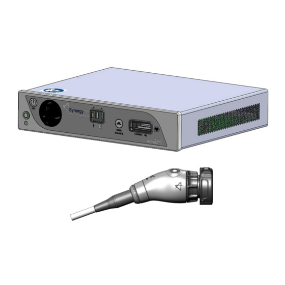
Page 13: System Indicators
UHD4 Figure 1- Synergy Front Panel [AR-3200-002x] System Indicators UHD4 1.9.1 Synergy Front Panel 3. USB Port-Connect USB devices here. 4. iPAD USB Port-Connect iPAD to this port. 1. On/Standby Switch-The On/Standby switch 5. “WHITE BALANCE” Button-Press to initiate toggles the Camera Control Unit (CCU) camera white balance. - Page 14 DVI-D format. Transceivers. Use Output 1 and 2 for 4K Video. Custom SFP+ Fiber Transceivers and Matrix 2. Display Ports (2X)-Supplies UHD Video License may be obtained from Arthrex Signal output in either 1.1 [dual cable] or 1.2 Customer Service. [MST].
- Page 15 Figure 3- AR-3210-0023 4K SynergyUHD4 Camera Head, autoclavable Figure 4- AR-3210-0029 4K SynergyUHD4 Broadband Camera Head, autoclavable 950-0047-04A Page 15 of 69...
- Page 16 Figure 5-AR-3210-0018 HD, SynergyUHD4 Camera Head, autoclavable Figure 6-AR-3210-0031 4K Ultra SynergyUHD4 Camera Head, autoclavable 1.9.3 Camera Heads with Integrated Optics 1. Button 1-A programmable button that can activate various functions of the 3. Focus Ring-Used to sharpen, or bring camera.
- Page 17 Figure 7-AR-3210-0025 4K SynergyUHD4 C-Mount Camera Head, autoclavable, AR-3210-0028 4K SynergyUHD4 C-Mount w/20 foot cable, autoclavable and Not Pictured AR-3210-0026 4K SynergyUHD4 C-Mount Camera Head, 0 Degree, autoclavable Figure 8-AR-3210-0030 4K SynergyUHD4 C-Mount Broadband Camera Head, autoclavable 950-0047-04A Page 17 of 69...
- Page 18 Figure 9- AR-3210-0021 HD SynergyUHD4 C-Mount Camera Head, autoclavable, and Not Pictured AR-3210-0022 HD SynergyUHD4 C-Mount Camera Head, 0 Degree, autoclavable Figure 10- AR-3210-0032 [4K Ultra SynergyUHD4 C-Mount Camera Head, autoclavable] 1.9.4 C-Mount Camera Heads 2. Button 2-A programmable button that 1.
- Page 19 950-0047-04, Rev. A English AR-3210-XXXX Camera Head SynergyUHD4 Firmware Compatibility CAUTION: • Some AR-3210-XXXX camera heads are only compatible with specific SynergyUHD4 firmware versions as shown in the following table. Attempting to use these camera heads with incompatible SynergyUHD4 firmware may fail to produce an acceptable quality video output on the surgical display.
-
Page 20: System Installation And Operation With Data Input Device
On/Standby Switch will not input of the display monitor. (3G-SDI or DVI activate the LED light engine until one is cables may be used instead of Display Port connected. cables.) Note: Arthrex recommends UHD4 connecting Synergy to the primary 950-0047-04A... - Page 21 950-0047-04, Rev. A English UHD4 Figure 12- Synergy Typical Interconnect Diagram With OPTIONAL Digital Documentation Tablet [Integrated Optics Heads] 950-0047-01A Page 21 of 69...
-
Page 22: Accessories For Intended Use
Description AR-3250-XXXX Arthrex Monitors SONY UP-PR80MD Medical Grade Printers SONY UP-PR80MD with UP- DR80MD/NKIT AR-3350-XXXX Arthrex Arthroscopes AR-3351-XXXX Arthrex Laparoscopes AR-3352-XXXX Arthrex Hi Mag Laparoscopes AR-3355-XXXX Arthrex C-Mount Arthroscopes AR-3200-1007 SynergyUHD4 Synergy Documentation Tablet AR-3200-1013 950-0047-04A Page 22 of 69... - Page 23 AR-3200-1030, -1034, -1036, -1042, -1043, Synergy.net Licenses -1044, -1045, -1046, -1047, -1049 AR-3210-XXXX Arthrex C-mount couplers AR-3200-1010, -1012 Arthrex encrypted USB sticks AR-3200-1040 Arthrex Synergy System Integration Cable Kit AR-3370-0006 Arthrex Starfish AR-3370-0008 Arthrex C-Mount Starfish AR-3201-1005 Video Input-Output 1080P Converter AR-3240-XXXX...
-
Page 24: System Setup Facility And Surgeon Settings
System Setup Facility and Surgeon Settings UHD4 NOTE: Facility, surgeon, and procedural settings are made from the Synergy ’s Tablet Data Input Device. Screens may appear slightly different than those shown in this document depending on UHD4 the particular features enabled on Synergy Figure 14-System Maintenance 2.3.1 System Set-Up can be accessed by pressing the Maintenance Icon... - Page 25 Figure 15-System Maintenance Screen 2.3.2 Selecting “System” enables several facility preferences to be setup; • UHD4 User can input the facility name associated with that specific Synergy • UHD4 User can select the language used with Synergy • User can select number of cases saved to system before data is automatically purged. •...
- Page 26 Figure 16-Date & Time Screen UHD4 2.3.3 Selecting “Date & Time” enables adjustment of the Synergy date and time settings. • User can use a network time server or user can select the date and time options manually. 950-0047-04A Page 26 of 69...
- Page 27 Figure 17-Print Settings Screen UHD4 2.3.4 Selecting “Print Settings” enables adjustment of the Synergy print settings. • User can enable the use of a local printer and select the paper size for that printer. 950-0047-04A Page 27 of 69...
- Page 28 Figure 18-System Maintenance Network UHD4 2.3.5 Selecting “Network” allows for connecting the Synergy system to a facility network. Fields are: • Ethernet IP Mode • Host Name • Ethernet IP Address • Ethernet Subnet Mask • Ethernet Default Gateway Note: If DHCP option is selected, then the Ethernet address is acquired automatically and no fields need to be completed.
- Page 29 Figure 19-Surgeon Management List 2.3.6 Surgeons can be added to the Synergy UHD4 with their own system preferences. 2.3.7 To add surgeons and their preferences, press the maintenance icon on the UHD4 Synergy Tablet Data Input Device and then select Surgeon Management. A list of surgeons will appear.
- Page 30 Figure 21-Surgeon Preferences Settings 2.3.9 Surgeon preferences can be defined for the following: • Camera Button Settings • Printer Settings • Print Settings • Multimedia • Web Server Access • Display • UHD4 BioOptico (Note: BioOptico is optional functionality for Synergy 950-0047-04A Page 30 of 69...
- Page 31 Figure 22-Surgeon Management Procedures Select 2.3.10 Procedure preferences can be added to individual surgeon preferences. On the surgeon management list, select a surgeon, and a list of procedures will appear 2.3.11 Select the appropriate Procedure for the Surgeon. If the procedure is not currently in the list, select the “Create New Procedure”...
- Page 32 Figure 23-Surgeon Procedure Settings 2.3.12 Once a Procedure has been added select the “Procedure Settings” next to the Procedure name to configure camera, pump, and shaver settings associated with the Procedure. 950-0047-04A Page 32 of 69...
-
Page 33: Icon Guide
Icon Guide 2.4.1 Figure 24 shows what is displayed on a surgical monitor when a SynergyUHD4 is first powered Figure 24-Connectivity Icons 2.4.2 In the lower left corner of the screen are icons that represent connectivity with SynergyUHD4. The icons shown below represent tablet, network, and Synergy.net connectivity. 2.4.3 The icons on the lower right of the monitor represent local and external peripheral connectivity (e.g., printer, USB, iPad, DICOM, network export) as shown in the figures below. - Page 34 2.4.4 Beneath each of the icons is a status bar. The color of the bar indicates the status of the connection. A status bar that is green means that there is active connectivity between that device and SynergyUHD4 and no issues are detected. A status bar that is blue means that there is active connectivity between that device and SynergyUHD4, no issues are detected, and an active data transfer is taking place (e.g., images are exporting to a USB device or a DICOM export is ongoing).
-
Page 35: Scheduling And Starting Cases
Scheduling and Starting Cases Figure 25-Scheduling a case 2.5.1 To schedule a case, press the “+ Add New Case” icon 950-0047-04A Page 35 of 69... - Page 36 Figure 26-Scheduling a Case 2.5.2 Select the “Room” (if present, optional field depending on how system is configured), “Surgeon” and/or “Procedure,” and enter data in the following required fields. • Patient First Name • Patient Last Name • Patient I.D. # 2.5.3 Input any of the other optional data elements in the appropriate fields.
- Page 37 Figure 27-Starting a Case 2.5.5 To start a case, select the case/patient from the Case List and press the “Start” icon. NOTE: Cases may also be started from the “Add Case” screen by entering the required fields and pressing the “Start” icon. 950-0047-04A Page 37 of 69...
- Page 38 Figure 28-Confirming a Case 2.5.6 A “Case Confirmation” window will appear showing the patient and case demographics. If the information is correct press the “Start” icon. 950-0047-04A Page 38 of 69...
- Page 39 Figure 29-Camera Head Button Change During Case 2.5.7 Changes to SETTINGS may be made during the procedure by pressing the “Maintenance Icon”. Changes may be made to the following: • Camera Head Button Functions • Print Settings 950-0047-04A Page 39 of 69...
- Page 40 Figure 30-Print Changes During Case 950-0047-04A Page 40 of 69...
- Page 41 Figure 31-Ending a Case 2.5.8 Ending a Case; to end a case, press the “End Case” Icon. NOTE: An “End the Case?” confirmation message will appear. If confirmed, the case will end UHD4 and the Synergy Tablet Data Input Device will transition to the case review screen. 950-0047-04A Page 41 of 69...
-
Page 42: Status Notification Icons
Status Notification Icons Figure 32-Status Notification Icons 2.6.1 When a manual export/print is performed, the status notification for the action will appear on the tablet. The blue progression bar will indicate that the export is in progress. Once the export is complete the status bar will turn green. - Page 43 Figure 33-Export Status 2.6.2 The system in Figure 33 displays a successful USB export and an iPad export in progress. 950-0047-04A Page 43 of 69...
- Page 44 Figure 34-Export and Print Status During a Case 2.6.3 Export and print statuses will also display during surgery if auto export or auto print is enabled for the surgeon using the system. A successful export will display a green checkmark for the images completed.
-
Page 45: System Operation Without Tablet Data Input Device
2. The camera will take approximately 60 System Operation without Tablet seconds to fully load its boot software. Data Input Device When the software has fully loaded, you UHD4 will see the Synergy Initial Screen UHD4 1. Connect the Synergy System per shown below in Figure 35. - Page 46 Figure 36-White Balance OK • When the White Balance has not been completed successfully, a Red X with WHITE BALANCE below will be shown on screen. Figure 37-White Balance Fail 13. If the White Balance Operation has been successful, the camera will enter the Surgical Ready Mode and be ready for surgical operation.
-
Page 47: Maintenance
If it becomes necessary to return the camera head to Arthrex for service, please sterilize the camera head before shipping. -
Page 48: Cleaning And Sterilizing
Cleaning and Sterilizing Follow universal precautions for protective apparel when handling and cleaning contaminated instruments. 3.3.1 Cleaning the LED Light Engine 1. Allow LED Light Engine to cool for ½ hour before cleaning. 2. Dampen one end of a cotton swab with isopropyl alcohol. 3. - Page 49 If the camera head is dented or damaged, or if the cable silicone jacket is cut, DO NOT autoclave or immerse in liquid (water, chemical disinfectants or sterilants, etc.). Notify your Arthrex Sales Representative. • Do not place the camera head or accessories in an ultrasonic cleaner or ultrasonic washer/sterilizer.
- Page 50 9. CAUTION: Inspect the camera head cable for breaks and cuts. Camera heads with damaged cables should not be sterilized or disinfected. Return camera heads with damaged cables to Arthrex for repair. 10. Before sterilization and/or disinfection, coil the camera head cable into loops at least six inches in diameter.
- Page 51 DEVICE STERILIZATION METHODS The following cycles have been validated for AR-3210-XXXX Camera Heads to provide a sterility assurance level (SAL) of 10 System Cycles • V-PRO® 1 Low Temperature Sterilization System [Standard Cycle] Steris® Systems • V-PRO® 1 Plus Low Temperature Sterilization System [Lumen and Non-lumen Cycles] •...
-
Page 52: Troubleshooting
Troubleshooting Symptom Possible Cause Corrective Action Camera does not • Plug power cord into CCU and/or a • Power cord is unplugged. power up. Standby properly grounded receptacle. • Suspect power cord. LED does not • Replace power cord. illuminate. •... - Page 53 • Suspect camera head and/or camera head and/or cable cable. were faulty, return them to • Camera head cable Arthrex for repair. • Insert camera head cable connector not inserted correctly or completely. connector completely into the CCU’s camera head receptacle on the front panel.
- Page 54 Symptom Possible Cause Corrective Action • Verify Tablet cable and connector are not damaged. If damaged, contact Arthrex Technical Support for further assistance. • Ensure charger is a Samsung mode EP- TA10JWE that has a • Damage to Tablet minimum of 2.0A of charge Tablet continually restarts or will current.
-
Page 55: Resolving Error Messages
Resolving Error Messages Error Message Corrective Action If not resolved, contact Arthrex Technical Cannot connect to Synergy. Touch to try again. Support for further assistance. User account is locked. Contact site administrator for assistance. User not assigned to valid network group. -
Page 56: Technical Information
Technical Information NOTE: Technical data is subject to modification, revision and improvement without notice. Safety, EMC and Regulatory Requirements Parameter Parameter Value FDA Class Class II EU Class Class I System Classification Health Canada Class Class II • Domestic Certification ANSI/AAMI ES60601-1/A1:2012 •... - Page 57 1920 x 1080 pixels [1080p], 8-bit color Video Outputs 3G-SDI (4x) 1920 x 1080 pixels [1080p], 8-bit color 3840 x 2160 pixels [4K/UHD], 8-bit color (AR-3200-0020 [CCU, Synergy UHD4, Matrix Video (2x) Matrix] and AR-3200-0022 [CCU, Synergy UHD4, Matrix, HCRI ]) Vertical Scanning 59.94 Hz...
- Page 58 4” [L] x 1.8” [W], x 1.8” [H] AR-3210-0018 Approximately 10.1 cm [L] x 4.5 cm [W] x 4.5 cm [H] AR-3210-0021 2.7” [L] x 1.2” [W], x 1.3” [H] Approximately 6.9 cm [L] x 3.0 cm [W] x 3.3 cm [H] 2.7”...
- Page 59 AR-3210-0018 19.6 ounces [0.6 kg] Approximately AR-3210-0021 17.1 ounces [0.5 kg] Approximately AR-3210-0022 17.9 ounces [0.5 kg] Approximately AR-3210-0023 21.0 ounces [0.6 kg] Approximately AR-3210-0025 17.4 ounces [0.5 kg] Approximately AR-3210-0026 17.4 ounces [0.5 kg] Camera Head Weight Approximately AR-3210-0028 27.4 ounces [0.8 kg] Approximately: AR-3210-0029...
- Page 60 LED Light Engine Specifications Parameter Parameter Value Minimum: 1600 Lumens Standard Typical; 1800 Lumens Light output Minimum: 1000 Lumens HCRI Typical; 1125 Lumens 70 CRI Typical, 65 Minimum Standard LED Light Engine 5500-8500K Specifications Color Temp 92 CRI Typical, 90 Minimum HCRI 5200-6700K LED Life...
-
Page 61: Appendix [Radio Module Information]
(2) this device must accept any interference received, including interference that may cause undesired operation CAUTION: changes or modifications not expressly approved by Arthrex will void the user’s authority to operate this equipment. Industry Canada Information: Contains IC: 4104A-AR5B225 IC Model;... -
Page 62: Appendix [Detailed Emc Information]
disturbing other Equipment and Systems or non-medical electrical equipment. APPENDIX [Detailed NOTE: Medical Electrical Equipment needs EMC Information] special precautions regarding EMC and needs to be installed and put into service according to the EMC information provided in the DETAILED EMC INFORMATION Accompanying Documents. - Page 63 Guidance and manufacturer’s declaration – electromagnetic emissions The Arthrex UHD4 Video System is intended for use in the electromagnetic environment specified below. The customer or the user of the Arthrex UHD4 Video System should ensure that it is used in such an environment. Emissions Test...
- Page 64 Guidance and manufacturer’s declaration – electromagnetic immunity The Arthrex UHD4 Video System is intended for use in the electromagnetic environment specified below. The customer or user of the Arthrex UHD4 Video System should ensure that it is used in such an environment.
- Page 65 To access the electromagnetic environment due to fixed RF transmitters, and electromagnetic site survey should be considered. If the measured field strength in the location in which the Arthrex UHD4 Video System is used exceeds the applicable RF compliance level, above, the Arthrex UHD4 Video System should be observed to verify normal operation.
- Page 66 Arthrex UHD4 Video System The Arthrex UHD4 Video System is intended for use in an electromagnetic environment in which radiated RF disturbances are controlled. The customer or the user of the Arthrex UHD4 Video System can help prevent electromagnetic interference...
-
Page 67: Appendix [Sw Version Access]
APPENDIX [SW Version access] UHD4 ACCESS to SW Version on Synergy 1. On POWER ON, the screen below appears. 2. Double click on screen to pull up SW Version. 3. Then Tap “About” Figure 34-Logging on to Android Figure 35-About Screen Figure 36-SW Version Screen 950-0047-04A Page 67 of 69... - Page 68 THIS PAGE INTENTIONALLY LEFT BLANK 950-0047-04A Page 68 of 69...
- Page 69 Naples, FL 34108-1945, USA Customer Service +1 (800) 934-4404 Arthrex, Inc. Toll-Free Technical Support: 1-(800) 391-8599 Monday through Friday, 8:00 AM – 8:00 PM ET www.arthrex.com Arthrex GmbH Erwin-Hielscher-Strasse 9 81249 München, Germany +49 89 909005-0 All rights reserved. Printed in USA.
Need help?
Do you have a question about the AR-3200-0020 and is the answer not in the manual?
Questions and answers