Advertisement
Quick Links
INSTALLATION AND OPERATING INSTRUCTIONS FOR
F26 SERIES HEAVY DUTY FLOW SWITCHES
PLEASE READ THIS INSTALLATION SHEET CAREFULLY AND FULLY
BEFORE INSTALLING OR SERVICING THIS FLOW SWITCH.
INTRODUCTION
The F26 series flow switch is a versatile heavy-duty paddle flow
switch suitable for detecting flow or no flow conditions in liquids
flowing in pipes of any diameter from 25mm upward. The
switch is available in two versions, a polypropylene model
designated F26-S, and a stainless body version designated
F26-SS. Both switches are identical with the exception of the
stainless body. The standard polypropylene switch is suitable
for most applications where static or dynamic pressures are
less than 18 Bars. The stainless version can safely tolerate
pressures to 100 Bars. The F26-SS has the advantage of higher
mechanical strength and finds application in fire prone or
vandal prone areas and is also suitable for marine use. Both of
the standard models are available with a high Amperage switch
capable of directly controlling single phase pump or fan motors,
to 1.5kW 2HP. These switches are designated F26-H
(polypropylene version) and F26-HS (316 stainless version).
OPERATING ENVIRONMENT
Maximum operating pressure
(static or dynamic) at ambient
temperature.
Minimum burst pressure at
ambient temperature.
Maximum operating
temperature (Liquid)
Minimum operating temperature
(Liquid)
Process liquid Ph range
Ingress protection rating
(Housing)
Note: temperature for the maximum operating pressure shown in the above
operating environment table is 15°C, In the interest of safety, when using the
polypropylene version of the F26 series, maximum operating pressure must be
de-rated linearly in direct proportion to temperature increase, to a maximum
pressure of 1 bar absolute at 80 degrees Centigrade. In other words only use
this switch at elevated temperatures in non pressurised systems that are
totally open to atmosphere in all circumstances and under all conditions.
INSTALLATION
Select a location for the flow switch in a straight run of pipe
ideally with five pipe diameters of straight pipe either side of
the switch. This will ensure a linear non turbulent flow acts
against the paddle of the switch. Do not install the flow switch
in any location likely to expose it to excessive turbulence,
such as directly adjacent to valves or pumps, pipe bends or
elbows. The object is to achieve a smooth flow against the
paddle of the switch and thus obtain a stable non-chattering
response from the flow switch. The F26 flow switch can be
mounted in either the suction or discharge pipe of a pump, the
switch will respond equally well in a negative pressure
situation as well as in a positive pressure application.
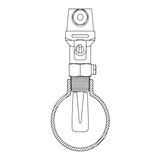
The F26 flow switch is supplied with an extra long paddle
suitable for flow sensing in large diameter pipes. The paddle
will require trimming to allow installation in smaller diameter
pipes. The paddle can be cut and shaped as required using
tin snips or similar tools. See the accompanying table for
recommendations on paddle lengths. Note that the paddle
can be cut both in length and if required, in width. Many
installers maintain a more stable flow response can be
obtained by narrowing down the paddle, and thus avoiding
turbulence close to the walls of the pipe.
The F26 flow switch can be installed in either horizontal or
vertical piping, at right angles to the pipe, or at any angle up
to 45˚ off the vertical axis. Do not install the flow switch on the
underside of horizontal pipes, or in any orientation where
debris may accumulate in the pocket in the switch body and
ultimately prevent the switch from operating.
18 Bars (260 PSI) polypropylene model
100 Bars (1450 PSI) Stainless model
80 Bars (1160 PSI) polypropylene
model
400 Bars (5800 PSI) Stainless model
80 Degrees C at a pressure 1 bar
absolute, see note below
-30˚C
1 to 14
IP67
A suitable 25mm (1") B.S.P. female thread socket must be
provided to fit the flow switch. This may be a tapping saddle
or a pipe tee, or a socket welded directly to the piping. Ensure
that whatever fitting is used, sufficient clearance is allowed for
the free movement of the paddle. Normally a clearance to the
full inside diameter of the 1" B.S.P. thread (28mm) will be
required. The F26 flow switch can be installed in a one inch
B.S.P. socket attached to a short stand off pipe, at 90˚ to the
main pipe. This method increases the sensitivity of the switch
to low flows due to the extra leverage against the tip of a
longer paddle.
If it is implemented, please ensure extra
clearance is allowed for the free radial movement of the
longer paddle.
Use thread tape or sealant and tighten the switch into the
socket using the spanner flats provided on the switch body.
Do not tighten the switch into its socket by twisting the switch
body, as damage to the flow switch may result. Align the flow
switch squarely to the axis of the pipe, with the direction of
flow arrow on the switch body pointing correctly and aligned
along the pipe. This flow switch will not function correctly
unless the alignment is correct.
When installing the flow switch in vertically running pipework,
note that the sensitivity of the switch will be slightly increased,
it will detect lower flows when flow is downward and will be
slightly decreased when flow is upward. This is due to the
effect of gravity and the dead weight of the paddle itself. This
effect is more noticeable in larger pipes and low flows where
long paddles may be used.
MANUAL OVERRIDE
The F26 flow switch has a built in manual override, located
under the cable gland on the end face of the switch. The
rotary toggle switch is marked AUTO and ON. In the AUTO
position the flow switch responds solely to flow, and the
toggle switch has no effect. In the ON position the flow
switch is actuated regardless of the state of the actual flow,
that is, the switch is turned on. The override feature is handy
for testing new installations, commissioning systems and for
manually priming pumps or starting diesel pump sets etc. In
normal operation the override switch should be rotated fully
into the AUTO position. Do not operate the flow switch with
the override partly between auto and on, as it may not
function correctly.
CROSS SECTION OF
TYPICAL INSTALLATION
Advertisement

Related Manuals for KELCO F26 Series


Summary of Contents for KELCO F26 Series
- Page 1 BEFORE INSTALLING OR SERVICING THIS FLOW SWITCH. INTRODUCTION The F26 series flow switch is a versatile heavy-duty paddle flow switch suitable for detecting flow or no flow conditions in liquids flowing in pipes of any diameter from 25mm upward. The...
- Page 2 PLEASE NOTE: Kelco Engineering Pty Ltd reserves the right to change the specification of this product without notice. Kelco Engineering Pty Ltd accepts no liability for personal injury or economic loss as a consequence of the use of this product. All rights reserved copyright Kelco Engineering Pty Ltd © 2008.
Need help?
Do you have a question about the F26 Series and is the answer not in the manual?
Questions and answers