Table of Contents
Advertisement
Quick Links
Advertisement
Table of Contents

Related Manuals for Madur GA-12plus


Summary of Contents for Madur GA-12plus
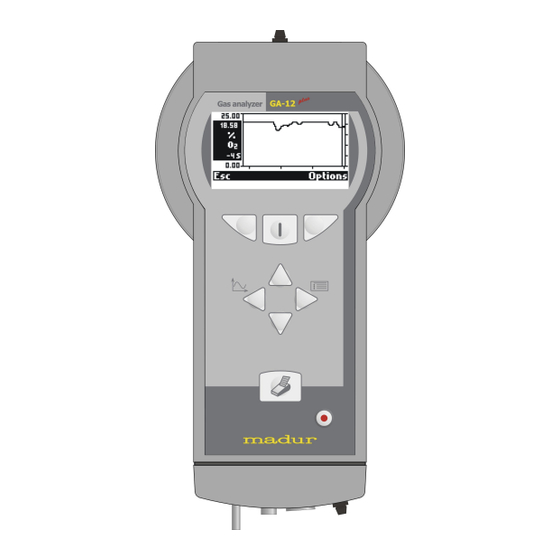
- Page 1 FLUE GAS ANALYSER GA-12 PLUS Operating manual 03/ 2013 V 0.99...
-
Page 2: Table Of Contents
Manual plus GA-12 Index 1.Description of GA-12plus analyser................3 2.Maintance.........................4 2.1. Electrochemical cells.....................4 2.2. Gas channel......................4 2.3. Battery........................4 2.4. Service........................5 2.5. Errors........................5 2.6. Switching off after use...................5 3.Operation..........................6 3.1. Use of the keyboard....................6 3.1.1. Description of the keys..................7 3.1.2. Editing numbers....................7... -
Page 3: Analyser
GA-12plus is a mobile boiler gas analyser extending the series of our well-known GA-12 analysers. There can be up to four gas sensors installed in the device. The basic version of the device is adjusted to measure the concentration of following gases: O2, CO, NO. -
Page 4: Maintance
Manual plus GA-12 2. Maintance 2.1. Electrochemical cells To extend the lifetime of the cells and guarantee the accuracy of the measurements the points listed below should be followed. The cells should not be exposed to influence of the concentration exceeding the •... -
Page 5: Service
Manual plus GA-12 2.4. Service Due to the fact that electrochemical cells’ parameters change with time it is necessary to carry out a periodical service connected with either the calibration of the electrochem- ical cells or their replacement. We recommend that service be carried out every 12 months or after the device have worked for 200 hours. -
Page 6: Operation
Manual plus GA-12 3. Operation 3.1. Use of the keyboard The analyser's apparence... -
Page 7: Description Of The Keys
Manual plus GA-12 3.1.1. Description of the keys - Left function key. Carries out the function shown on the display whilst the instrument is switched on. - Right function key. Carries out the function shown on the display whilst the instrument is switched on. -
Page 8: Basic Operation
Manual plus GA-12 3.2. Basic operation 3.2.1. Getting started Connect the individual parts of the instrument: connect the gas probe. • ensure that the gas outlet is not blocked. • 3.2.2. Switching on The instrument performs a zero calibration immediately after being switched on. -
Page 9: Results Screens
Manual plus GA-12 3.3. Results screens The function keys Data or Esc will automatically call up the results screen from any point. Below there are two examples of results screens. 3.3.1. The info bar A) The number 1 stands for the first results screen. Four results screens can be defined. -
Page 10: Results
Manual plus GA-12 3.3.3. Results All the results of measurements and calculations are shown as averaged values. Aver - aging time is chosen by the user under Options from 2 – 6 – 10 – 20 – 30 – 60 – 120 –... -
Page 11: Menu
Manual plus GA-12 4. MENU From the results screens the following options can be activated with the keyboard: Store – Left function key. ● Action – Centre function key. ● Options – Right function key. ● Chart – Arrow left. - Page 12 Manual plus GA-12 Single XL test: The averaged results will be stored. The term XL (extra long) is used for the formation of especially long averages. XL test time can be set via Options second screen or on current screen by the use of the keys: Available times: 10sec, 20sec, 30sec, 1min, 2min, 5min, 10min, 15min, 20min, 30min.
- Page 13 Manual plus GA-12 If the memory of analyser is full, and no more reports can be stored the following screen is shown when the storage is attempted. The storing of results will be stopped and the instrument returns automatically to the results screen.
-
Page 14: Action Menu
Manual plus GA-12 function key is pressed during the X2 or X3 test, the measurement is disrupted but it’s result will be stored. During the XL test, its result can be viewed. Pressing the key during displaying the results screen, for a few seconds, the XL test results’ will be shown (averaged for the period of time since the beginning of the test). - Page 15 Manual plus GA-12 Pressure test The following screen will appear: The upper displayed value is the currently measured pressure value. The value in the frame is the value stored for a printout or a report. T2 in the right upper corner is the set averaging time. If the period of the time since the beginning of the measurement is shorter than the chosen averaging time, the current av- eraging time of the test will be displayed.
- Page 16 Manual plus GA-12 Soot test The soot test can be carried out provided that the analyser is being supplied with energy from outside. The efficiency of the pump powered by the inner battery is not enough to carry out the test. Also the heating of the probe holder (necessary when carrying out the soot test) requires that the instrument be powered by the mains adapter.
- Page 17 Manual plus GA-12 With the use of arrow keys the value taken from the comparative scale should be filled in and confirmed with OK key. It is possible to save three mesurements results ( X) which will be visible in a saved report.
- Page 18 Manual plus GA-12 After confirmation the first test starts followed by the second one. After the first and the second test summary will provide information about the pressure tightness. Ambient CO test This option is used to measure the ambient CO level. After this option is chosen the user will be asked if he want to start the test.
-
Page 19: Chart
Manual plus GA-12 Calibrate O2 for 20.95% plus In order to increase the accuracy of long-period measurements GA-12 has the pos- sibility of calibrating the O sensor on demand. Before choosing the command Calibrate O2 for 20.95 % the probe should be removed from the stack and the readings should be stabled. - Page 20 Manual plus GA-12 The menu bar Leaves the Chart and returns to the results screen. Options This opens the window for the Chart settings. The following screen appears: Description of the options: Marker Switches the marker on or off.
-
Page 21: Measurement Parameters
Change reference O2 value can be changed in the range 0-13% O Note: If option „Use O from fuel data” was ticked in service program madur- 2ref Portable then there is no possibility to change the reference oxygen in the instrument, this value is adopted from defined fuel parameters. - Page 22 Manual plus GA-12 There are also 4 memory locations (6-9) for 4 fuels specific to the user which can be freely programmed by the user. This is carried out using the madurPortable PC program. There is a possibility to replace the first standard fuels with the set of ÖNORM or Italian fuels.
-
Page 23: Main Menu
(when having problems with finding the proper setting in the analyser’s menu) it is possible to restore the default language by keeping the key pressed when starting the analyser. The choice of the default language is made in madur- Portable program. -
Page 24: Burner Regulation
Manual plus GA-12 4.5.2. Burner regulation This option allows the combustion process in a burner to be visualised. Three variables that define the combustion process are shown graphically. These are: CO – carbon monoxide concentration qA – stack loss Lambda –... -
Page 25: Reports
Manual plus GA-12 4.5.3. Reports This option is used to administrate the stored reports. The fields have the following meanings: A. The report number given to the report within the reports table (1..64). B. The creation date of the report. Displayed in the format defined in the menu Clock. - Page 26 Manual plus GA-12 After pressing the Print key the following screen will appear: Using Esc or No returns to the previous screen, choosing Yes starts printing. If the chosen report is a one from the triple XL test report, the following screen is displayed: Choosing Triple causes averaging and printing all three parts of triple report as a whole.
-
Page 27: Clock
Manual plus GA-12 4.5.4. Clock In the Clock Menu options the following settings (as shown in the picture) can be changed: Time The time displayed by the inner clock can be set. Date The date indicated by the inner calendar can be set. -
Page 28: Info
Manual plus GA-12 4.5.5.1. Info On the Info screen the information concerning the configuration of the instrument are displayed. Using the ↑↓ key will evoke the next Info screen. 4.5.5.2. Control list The option Control list shows all measured signals. This is of great use when search- ing for possible defects. -
Page 29: Calibration With Gases
Manual GA-12 plus The ↑↓ key is used to change between the consecutive screens of the Control List. 4.5.5.3. Calibration with gases Calibration with gases is about observing the sensors’ reaction to the familiar to the user gas concentration. The access to the calibration is originally blocked at the factory. If so after choosing the option the following screen will appear: Unblocking the calibration process is possible via the madurPortable PC program. -
Page 30: Pressure Calibration
Manual plus GA-12 The screen makes it possible to choose between the calibration gases. The process of calibrating will be presented for CO. The Change key evokes the screen used for entering the reference gas concentration value. After applying the gas to the instrument it is advised to wait until stable values appear in the S (signal) column and then to press the OK key. - Page 31 Manual plus GA-12 After choosing the pressure calibration option the following screen will appear: After confirmation the following screen will be displayed. The fields on the screen have the following meaning: Measured The signal currently supplied by the pressure sensor and the pressure measured by the instrument.
-
Page 32: Printing
Manual plus GA-12 4.6. Printing Using the arrow left/right keys for given line will cause the change of the printing format. There are four default, set at the factory formats, the other four can be defined by the user with the help of the PCGA12plus.exe program. -
Page 33: Flow Velocity Measurement
Manual plus GA-12 5. FLOW VELOCITY MEASUREMENT The GA12 analyser is able to measure the differential pressure of the flue gases and can be equipped with a Pitot tube with which the flow velocity measurement can be per - formed. - Page 34 Manual plus GA-12 The tube must be connected to the analyser inlets (the total pressure outlet of the tube – to the analyser’s differential pressure sensor inlet (+) and the static pressure outlet of the tube to the analyser’s differential pressure sensor inlet (-) ).
Need help?
Do you have a question about the GA-12plus and is the answer not in the manual?
Questions and answers