
Subscribe to Our Youtube Channel
Related Manuals for CodaOctopus F180R

Summary of Contents for CodaOctopus F180R
- Page 1 /F180R series very accurate positioning and motion data ™ F180R series User & Reference Guide Version: 2.0.0 Copyright © 2015 Coda Octopus Products Ltd...
- Page 2 ™ F180R series User & Reference Guide This guide describes the installation and configuration of the F180R™ series hardware and software developed by CodaOctopus that allows to produce highly accurate positioning and motion data in the most dynamic offshore conditions.
- Page 3 - without the written permission of the publisher. Coda®, Octopus®, F180®, F180R™, F170™ and F175™ are registered trademarks (Reg. U.S Pat & TM Off) or trademarks of Coda Octopus Group Inc.
-
Page 4: Table Of Contents
................................. 36 3.3.3 IMU Installation ................................. 40 Measure Installation Parameters ........................... 41 3.4.1 IMU Orientation ................................. 42 3.4.2 Antenna Offset ................................. 43 3.4.3 Antenna Separation ................................. 44 Copyright © 2015 Coda Octopus Products Ltd F180R MOTION Sensor User and Reference Guide... -
Page 5: Contents
5.2.1.2 Data Source - Replay ..............................85 5.2.2 Real Time Data ................................. 86 5.2.2.1 Setup Real Time Data Display ..............................87 5.2.3 System Status ................................. 88 Copyright © 2015 Coda Octopus Products Ltd F180R MOTION Sensor User and Reference Guide... -
Page 6: Contents
System Operation ..............................142 6.4.2 Network Troubleshooting ................................. 143 6.4.2.1 Physical Connection ..............................144 6.4.2.2 PC LAN Connection ..............................144 6.4.2.3 Testing The Network Connection ..............................146 Copyright © 2015 Coda Octopus Products Ltd F180R MOTION Sensor User and Reference Guide... -
Page 7: Contents
System Dimensions ........................... 149 6.5.1 F180R Reference Point ................................. 153 6.5.2 Antenna Reference Points ................................. 153 Measure Installation Worksheet ........................... 156 Corrosion Prevention ........................... 156 Index Copyright © 2015 Coda Octopus Products Ltd F180R MOTION Sensor User and Reference Guide... - Page 8 Chapter Export Policy...
-
Page 9: Chapter 1 Export Policy
Dual-use items are goods, software, technology, documents and diagrams which can be used for both civil and military applications. It is important when exporting a F180R System that you always keep a full record of all export destinations, dates and export documents. - Page 10 Chapter Introduction...
-
Page 11: Chapter 2 Introduction
GPS receivers. The F180R System is delivered with the IMU components in a separate waterproof pod (wetpod) in order to allow the IMU to be located close to a transducer head. -
Page 12: General Description
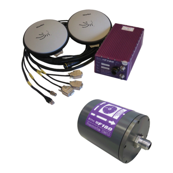
Unless otherwise stated, all measurements throughout this manual conform to the SI system of units. General Description The F180R System Inertial Attitude and Positioning System comprises four separate sub- systems: Figure 1: F180R System Unit, Antennas and Interfacing Cables the Inertial Measurement Unit with the interconnection cables... -
Page 13: Inertial Measurement Unit
110 – 240V mains powered supply. 2.1.2 GNSS System Two GNSS systems supply the information required by the F180R System to produce a heading solution. The antennas and the dual GNSS receiver cards are all designed for use in harsh marine environments where vibration and extremes of temperature are the norm. -
Page 14: Warranty
Calibration We recommend to factory calibrate the F180R System hardware every 2 years to ensure maximum accuracy. The calibration can't be performed in the field so please get in touch with the CodaOctopus Support team to arrange a hardware calibration. - Page 15 Chapter Hardware...
-
Page 16: Chapter 3 Hardware
PCs connected to the network to receive the transmitted MCOM data. It provides significantly greater data transfer capacity than a serial RS232 connection. To receive data from the F180R System system on a PC, the PC must have an Ethernet card fitted and be connected Copyright © 2015 Coda Octopus Products Ltd... -
Page 17: Serial Outputs
RJ–45 direct in–line coupler that has a straight–through configuration. You may also connect the F180R System system directly to an Ethernet card in a PC. To do this the Ethernet link must be a crossover connection. -
Page 18: Mcom
Binary data output string that include position, attitude, heading, velocity, track and speed, acceleration, status and performance and raw data. The MCOM format is a proprietary format defined by CodaOctopus. The format description is available to third parties who wish to implement libraries for decoding the MCOM data stream. -
Page 19: Ggk
DOP. It is considered a "pseudo-NMEA" string, because it looks similar to a standard NMEA string, but does not quite adhere to the NMEA specification. Copyright © 2015 Coda Octopus Products Ltd F180R MOTION Sensor User and Reference Guide... -
Page 20: Gsa
1 = Fix not available 2 = 2D 3 = 3D IDs of the satellites used in the solution. This field is repeated 12 times. (null for unused fields) PDOP Copyright © 2015 Coda Octopus Products Ltd F180R MOTION Sensor User and Reference Guide... -
Page 21: Gsv
Integrity Monitoring (RAIM). Psuedorange measurement error statistics can be translated in the position domain in order to give statistical measures of the quality of the position solution. Copyright © 2015 Coda Octopus Products Ltd F180R MOTION Sensor User and Reference Guide... -
Page 22: Hdt
The PPS (Pulse Per Second) is a non-standard NMEA message which is useful for integrating the F180R System with other devices. This message contains useful information such as the PPS count, the UTC time of the current PPS, and other time-related information. -
Page 23: Prdid
The angular rates for roll and pitch are also included. This sentence only contains the orientation measurements accurate to 1 decimal place so it is not suitable for high accuracy applications. Copyright © 2015 Coda Octopus Products Ltd F180R MOTION Sensor User and Reference Guide... - Page 24 Lateral angular rate (pitch rate) of the navigation system, measured in degrees/ second, with leading sign, leading 0’s where needed and 2 decimal places. Positive values mean that the front is moving up. Checksum separator and checksum Copyright © 2015 Coda Octopus Products Ltd F180R MOTION Sensor User and Reference Guide...
-
Page 25: Rmc
E = Easterly variation from True course (subtracts from True course) W = Westerly variation from True course (adds to True course) Mode indicator A = Autonomous D = Differential N - Data not valid Checksum Copyright © 2015 Coda Octopus Products Ltd F180R MOTION Sensor User and Reference Guide... -
Page 26: Rot
Figure 15: UTC String 3.1.2.2.14 VTG The NMEA - VTG string contains the actual course and speed relative to the ground. Figure 16: NMEA - VTG Format Copyright © 2015 Coda Octopus Products Ltd F180R MOTION Sensor User and Reference Guide... -
Page 27: Zda
The TSS1 data string format has five fields and contains 27 ASCII characters. Each string begins with a start character and ends with the carriage return and line–feed characters. All fields contain measurements in real–world units - the F180R System supplies acceleration measurements using ASCII–coded hexadecimal values and heave, pitch and roll as ASCII–... -
Page 28: Tss Hhrp
The HHRP sentence contains attitude data. Figure 19: HHRP String 3.1.2.5 EM1000 (Tate-Bryant) This 10–byte binary format is for use with the Simrad EM1000 multibeam sounder system. Figure20: EM1000 Format Copyright © 2015 Coda Octopus Products Ltd F180R MOTION Sensor User and Reference Guide... -
Page 29: Em3000 (Tate-Bryant)
Figure 21: EM3000 Format 3.1.3 RTK and Differential Corrections The F180R System can decode corrections supplied in RTCM, RTCA and CMR and CMR from external GPS receivers or standalone demodulators. The system is configured by default to receive RTK and differential correction information, using the RTCM format with default input port settings 9600,8,N,1,OFF. -
Page 30: Pps
CodaOctopus operates a policy of continual product improvement. The technical specification listed below for the systems manufactured at the time of writing and is therefore subject to change without notice. For details of current specifications, refer to the CodaOctopus website Copyright © 2015 Coda Octopus Products Ltd... -
Page 31: Model Specifications
20 cm positional accuracy. Additional subscription is required. F190R+ As F190R but with L1/L2 enabled on both receivers for rapid heading initialisation. Copyright © 2015 Coda Octopus Products Ltd F180R MOTION Sensor User and Reference Guide... -
Page 32: Interfaces
Serial 3 Input RTK/Differential Correction Input RS232 (DB9) up to 115k baud. Receive (Rx) pin on J3 is Pin 3 for correction input Other 1 PPS Copyright © 2015 Coda Octopus Products Ltd F180R MOTION Sensor User and Reference Guide... -
Page 33: Reference Frames
F180R System Standard Orientation Figure 23: Local Reference System NOTE: The IMU frame for the F180R System wetpod are defined with positive y-axis through connector plate and positive x and z-axis according to marking on the unit itself. Lever Arm Convention If you have specified a Remote Lever Arm then the position, velocity, heading, heave and attitude data are for the remote lever arm location. -
Page 34: Hardware Installation
These instructions explain how to install and connect the components of the F180R System. Although it is easy to install and configure the system, you should take some time to read these instructions and identify each of the components of the system before you begin so that you can be sure you have everything you need readily available. - Page 35 IMU or subject it to shocks. A 'Shockwatch' label attached to the IMU casing will show a red central vial if the unit is subjected to severe shock. If this occurs, return the unit to CodaOctopus Limited for test and repair. The solid–state inertial measurement components are not field repairable.
-
Page 36: Antenna Installation
NOTE: You should consult the documentation for any microwave emitters or radar antennas mounted on the vessel close to your proposed F180R System antenna mounting location. The F180R System antennas are sensitive to any electromagnetic radiation that might interfere with electrical equipment. - Page 37 Hardware NOTE: The F180R System comes with a standard set of 15m (Novatel CO16) antenna cables with options for 5m (Novatel C006) and 30m (Novatel C031). Refer to Appendix - Antenna Cable for further technical information on antenna cables. the optional antenna mounting bar (supplied on request)
- Page 38 5. Run one of the supplied cables from the F180R System Box to the primary GPS antenna location. Use clips or adhesive tape to secure the cable at regular spacings. Do not subject the cable to sharp bends, stresses or points where extended vibration might cause wear to the cable.
- Page 39 PRODUCTNAME%> Box side Marine connector IMU Pod connection, connection on the IMU pod side Open tails Supply, supply return and ground Figure 25: F180R System Connectors Diagram Copyright © 2015 Coda Octopus Products Ltd F180R MOTION Sensor User and Reference Guide...
-
Page 40: Imu Installation
In particular, be very careful when you place the F180R System IMU on or mount it to any surface. It is not possible to repair the inertial measurement components of the F180R System IMU in the field. If you suspect the F180R System has developed a fault, return it to CodaOctopus for repair. -
Page 41: Measure Installation Parameters
Hardware NOTE: The F180R System Box is NOT waterproof. Do not install it where it is likely to become wet at any time. However the IMU/wetpod is. Choose a location for the Box and IMU that allows you to connect it to other components of the system easily using the supplied cables. -
Page 42: Imu Orientation
The standard installation orientation of the F180R System relative to the vessel is for the connector end plate to point directly aft. The system should also sit level relative to the mounting surface. This orientation will ensure the system is installed parallel to the vessel's heading axis. -
Page 43: Antenna Offset
3.4.2 Antenna Offset It is necessary to configure the F180R System with Antenna Offset parameters that describe the position of the primary GNSS antenna relative to the F180R System IMU. To provide this important information you must measure the antenna offset distances. -
Page 44: Antenna Separation
Hardware Fore-Aft offset—the distance between the installed position of the F180R System IMU and the centre of the primary GNSS antenna along the fore–aft line of the F180R System IMU. Port-Starboard offset—the distance between the installed position of the F180R System IMU and the centre of the primary GNSS antenna along the port–... -
Page 45: Antenna Orientation
3.4.5 Remote Lever Arms The F180R System allows you to set a 'Remote Lever Arm' distances X, Y and Z of the F180R System so that you may specify the point at which you want the motion outputs to be computed for. -
Page 46: Communication
Communication So far you have installed and interconnected the components of the F180R System Inertial Attitude and Positioning System so that they are ready for use. This chapter of the manual describes the various interface options and data output formats that you may use with the F180R System. -
Page 47: Ethernet
RS232 connection. To receive data from the F180R System system on a PC, the PC must have an Ethernet card fitted and be connected to the same 100 Base T local area network (LAN) over which the system is broadcasting. The PC must be running the supplied MOTION Control software. -
Page 48: Serial Outputs
RJ–45 direct in–line coupler that has a straight–through configuration. You may also connect the F180R System system directly to an Ethernet card in a PC. To do this the Ethernet link must be a crossover connection. -
Page 49: Mcom
Binary data output string that include position, attitude, heading, velocity, track and speed, acceleration, status and performance and raw data. The MCOM format is a proprietary format defined by CodaOctopus. The format description is available to third parties who wish to implement libraries for decoding the MCOM data stream. -
Page 50: Ggk
DOP. It is considered a "pseudo-NMEA" string, because it looks similar to a standard NMEA string, but does not quite adhere to the NMEA specification. Figure 30: NMEA - GGK Format Copyright © 2015 Coda Octopus Products Ltd F180R MOTION Sensor User and Reference Guide... -
Page 51: Gsa
HDOP VDOP Checksum 3.5.2.2.4 GSV The GSV message identifies the number of satellites in view, the pseudorange noise (PRN) numbers, elevation, azimuth, and signal-to-noise (SNR) value. Copyright © 2015 Coda Octopus Products Ltd F180R MOTION Sensor User and Reference Guide... -
Page 52: Gst
Integrity Monitoring (RAIM). Psuedorange measurement error statistics can be translated in the position domain in order to give statistical measures of the quality of the position solution. Figure 33: NMEA - GST Format Copyright © 2015 Coda Octopus Products Ltd F180R MOTION Sensor User and Reference Guide... -
Page 53: Hdt
The PPS (Pulse Per Second) is a non-standard NMEA message which is useful for integrating the F180R System with other devices. This message contains useful information such as the PPS count, the UTC time of the current PPS, and other time-related information. -
Page 54: Prdid
1 decimal place so it is not suitable for high accuracy applications. Figure 38: NMEA PTCF string Field Description HHH.H True Heading of the navigation system, from 0 to 359.99 degrees, using 1 decimal place. Copyright © 2015 Coda Octopus Products Ltd F180R MOTION Sensor User and Reference Guide... -
Page 55: Rmc
UTC time of the position fix in hhmmss.ss format Status A = Data valid V = Navigation receiver warning (V is output whenever the receiver indicates that something is wrong) llll.ll Latitude (WGS-84) Copyright © 2015 Coda Octopus Products Ltd F180R MOTION Sensor User and Reference Guide... -
Page 56: Rot
A = Autonomous D = Differential N - Data not valid Checksum 3.5.2.2.12 ROT The ROT sentence contains Rate of Turn data. Figure 40: ROT String Copyright © 2015 Coda Octopus Products Ltd F180R MOTION Sensor User and Reference Guide... -
Page 57: Utc
Figure 42: NMEA - VTG Format 3.5.2.2.15 ZDA The NMEA - ZDA string contains UTC time, day, month, year and local time zone information. Figure 43: NMEA - ZDA Format Copyright © 2015 Coda Octopus Products Ltd F180R MOTION Sensor User and Reference Guide... -
Page 58: Tss1
The TSS1 data string format has five fields and contains 27 ASCII characters. Each string begins with a start character and ends with the carriage return and line–feed characters. All fields contain measurements in real–world units - the F180R System supplies acceleration measurements using ASCII–coded hexadecimal values and heave, pitch and roll as ASCII–... -
Page 59: Tss Hhrp
The HHRP sentence contains attitude data. Figure 45: HHRP String 3.5.2.5 EM1000 (Tate-Bryant) This 10–byte binary format is for use with the Simrad EM1000 multibeam sounder system. Figure46: EM1000 Format Copyright © 2015 Coda Octopus Products Ltd F180R MOTION Sensor User and Reference Guide... -
Page 60: Em3000 (Tate-Bryant)
Figure 47: EM3000 Format 3.5.3 RTK and Differential Corrections The F180R System can decode corrections supplied in RTCM, RTCA and CMR and CMR from external GPS receivers or standalone demodulators. The system is configured by default to receive RTK and differential correction information, using the RTCM format with default input port settings 9600,8,N,1,OFF. -
Page 61: Pps
RTCM Version 3 messages. Please contact CodaOctopus for exact information on your F180R System model.) RTCA The F180R System will accept RTCA Standard Type 7 messages. CMR/CMR+ Trimble open format and available as an output from their instruments and some other 3rd party. - Page 62 Chapter Operation...
-
Page 63: Chapter 4 Operation
12.The system is now collecting motion data Power-on the System With all the cabling connected, including the Ethernet link to the host PC, start the F180R System by connecting power to it. Watch the LEDs on the system front panel to determine when the system is ready for you to begin using it. - Page 64 Operation Figure 50: F180R System connectors The standard LED sequence once the F180R System is ready is : Status - Green; Heading - Green; Position - Green; Data - Green. NOTE: A high data rate will cause the Data LED to show Orange instead of Green. The LED toggles Green - Orange, but at high data rates the Orange output is more frequent.
-
Page 65: Calibration
4.3.1 Pre-Calibration Checks Ensure the F180R System has been powered–on for 30 minutes from a cold start — it is not necessary to wait 30 minutes from a system restart — to allow the sensors inside the unit to reach a stable operating temperature. -
Page 66: Calibration Procedure
NOTE: The Remote Lever Arm data is not used during calibration and can be entered later if required. If the settings are correct then you should upload them and restart the F180R System from the MOTION Settings Wizard. 4.3.2 Calibration Procedure Once the configuration has been saved to the F180R System and the F180R System restarted, the system will commence the calibration routine automatically. - Page 67 Figure 52: Save Calibration You will also be able to save the calibrated settings to the F180R System from the Live tab -> Calibration - Save. After the settings have been stored, you can power–off and power–on the F180R System as necessary without affecting the calibration—the calibration settings are saved to non–volatile...
-
Page 68: Calibration Specification
Once calibrated, the calibration and the settings saved to the F180R System will remain valid for at least 6 months if the F180R System and the GNSS antennas are not disturbed; you MUST recalibrate the system if either the F180R System or the GNSS antennas are moved. -
Page 69: Invalid Calibration
GNSS offsets measurements incorrect measurement of the antenna separation distance incorrect antenna angular alignment relative movement between the IMU and the antennas high GPS multipath environment Copyright © 2015 Coda Octopus Products Ltd F180R MOTION Sensor User and Reference Guide... - Page 70 Operation If you are unable to achieve an acceptable calibration on the F180R System please contact technical support for further advice. Copyright © 2015 Coda Octopus Products Ltd F180R MOTION Sensor User and Reference Guide...
- Page 71 Chapter Software...
-
Page 72: Chapter 5 Software
2. Read the End User Licence Agreement and click the radio button to accept the agreement. You cannot install the software unless you accept the agreement. Click Next to continue. Copyright © 2015 Coda Octopus Products Ltd F180R MOTION Sensor User and Reference Guide... -
Page 73: Software Uninstallation
Windows Vista/7: Start > Control Panel > Programs > Programs and Features and use the Windows facility to uninstall the MOTION Control software from your PC. Copyright © 2015 Coda Octopus Products Ltd F180R MOTION Sensor User and Reference Guide... -
Page 74: Main Interface
Main Interface The main MOTION Control application interface provides access to all configuration, control and diagnostic functions that you will require to operate the F180R System hardware. Figure 53: MOTION Control Main Interface There are four main areas in MOTION Control:... -
Page 75: Data Source - Ethernet
Rebroadcast the MCOM data to another network and/or port. In addition to the View options on the Home tab the tabs Live Logging become available. Copyright © 2015 Coda Octopus Products Ltd F180R MOTION Sensor User and Reference Guide... -
Page 76: Ethernet Source - Live Tab
(.rd) file. An .rd file is automatically logged when the F180R System is running and is stored on an internal flash memory in the system. A new .rd file is started each time the F180R System is started or when the file size reaches 20MB and named with a yymmdd_hhmmss_# convention, where # is a sequential number incremented for each file. -
Page 77: Change Ip Address
4. Select OK to close the Raw Data Management interface MOTION Control will then start transferring files from the F180R System to the host PC. This is carried out as a background task. The system will transfer a file and then rest for a few minutes. -
Page 78: Update Firmware
Address to be included in the same subnet (netmask). To control the F180R System, the host PC must be on the same subnet address as the F180R System. If not, then the F180R System will operate in listen mode only. - Page 79 The unzipped package consists of a containing folder named after the firmware version e.g. 110822i0.14b which in turn contains the firmware packages. To update the firmware connect to the F180R System over Ethernet and on the Live tab click the Update Firmware button, then select the directory that contains the firmware. You will then have to confirm that you want to update the firmware.
-
Page 80: Rebroadcast Mcom
Software The message log will show some message about the update progress and the F180R System will eventually reboot. WARNING: While updating the firmware do not unplug the F180R System from the network or power supply, since this may damage the system. - Page 81 Software Figure 64: Calibration options Status Select Status to display the status interface for the F180R System calibration. Figure 65: Calibration Status with Advanced State Variables The four fields reported on the interface are: Copyright © 2015 Coda Octopus Products Ltd...
- Page 82 Select the Advanced button on the Calibration Status interface to display them. Save Select Save to save the calibration settings to the F180R System when the calibration has completed successfully. This commits the current calibration values to the system non-volatile memory.
-
Page 83: Ethernet Source - Logging Tab
5.2.1.1.2 Ethernet Source - Logging Tab The Logging Tab presents all the controls that are required to manage data logging on the F180R System. These include logging mode, start logging, stop logging and the file storage location. Figure 67: Logging Tab... - Page 84 When logging is started the button will be highlighted and Stop Logging will become available. Additionally an information message with the logging file location will be written to the Message Log. Copyright © 2015 Coda Octopus Products Ltd F180R MOTION Sensor User and Reference Guide...
-
Page 85: Data Source - Replay
Control also has the facility to log data to a file stored on the host PC. The data file, recorded in MCOM format, captures all the information from the F180R System in real-time throughout the survey. The resulting MCOM file can be played back and the recorded data can be viewed in the application data displays. -
Page 86: Real Time Data
The real time data area is displayed as part of the main application interface. It displays each of the main outputs of the F180R System as a numeric value and is dynamically updated 4 times per second to reflect the current real-time system outputs. -
Page 87: Setup Real Time Data Display
5.2.2.1 Setup Real Time Data Display Figure 73: Home Tab - Settings The application settings allow you to define the display units for the F180R System measurements and also set the measurement mode for speed and distance measurements. Figure 74: Real Time Data Display Settings Copyright ©... -
Page 88: System Status
'Free' - any motion at any speed is included in the distance measurements NOTE: The selections you make here do not affect the F180R System itself. They affect only the MOTION Control application. You may change the units at any time so that, for example, a logged data file that you recorded with the speed units set to metres/ second may be replayed with the units set to knots. - Page 89 Only if there is a control connection you can actively change the F180R System setup. Read-only connections occur if the application is running in playback mode; communicating with the F180R System using a COM port; or the PC with MOTION Control installed has the incorrect IP address set. See Change IP Address for information on how to change the IP Address.
- Page 90 The F180R System has detected a fault condition. Further information should appear in the form of message popups. Double clicking the Status LED will display the Graphical QC dialog. Copyright © 2015 Coda Octopus Products Ltd F180R MOTION Sensor User and Reference Guide...
- Page 91 Software The Calibration field displays the current calibration state of the F180R System. The system's outputs should not be used until the F180R System calibration is complete. This field can be one of five states: LED Colour Field Description Grey...
- Page 92 Double clicking the Navigation LED will display the Graphical QC dialog. The GPS Heading field can take one of the following 7 options: Copyright © 2015 Coda Octopus Products Ltd F180R MOTION Sensor User and Reference Guide...
- Page 93 Green Valid The positional information is valid and is being used. Double clicking the GPS Position LED will display the Graphical QC dialog. Copyright © 2015 Coda Octopus Products Ltd F180R MOTION Sensor User and Reference Guide...
- Page 94 The user has indicated that DGPS corrections are being supplied to the F180R System system. The user has indicated that RTK (2cm or 20cm) corrections are being supplied to the F180R System system. The Recalibration Date field can take one of the following 3 options: LED Colour...
-
Page 95: Message Log
This message is generated by the iHeave subsystem The symbols after the time stamp mean: (U) = UTC time obtained from system (L) = local time of PC Copyright © 2015 Coda Octopus Products Ltd F180R MOTION Sensor User and Reference Guide... -
Page 96: System Indicator
The MOTION Settings Wizard allows you to sequentially browse through and configure the parameters to suit your deployment. As well as being easy to setup, the F180R System is also easy to configure taking only a few minutes to complete the configuration prior to calibrating and using the system. -
Page 97: Introduction
PC. Use Previous Settings - Will load the last settings that were entered into the application. These will not necessarily be the same as the last settings saved to the F180R System. Copyright © 2015 Coda Octopus Products Ltd... -
Page 98: Orientation
5.3.2 Orientation Figure 78: MOTION Settings Wizard - Orientation This dialog specifies the orientation of the F180R System IMU in the vessel frame of reference. It is important that the F180R System IMU orientation in relation to the vessel frame is accurately measured and input. - Page 99 NOTE: The coordinate axis on the vessel drawing indicate the alignment using dashed red lines for IMU axis and solid black lines for Vessel axis. NOTE: Definitions of Heading, Pitch and Roll that are output by the F180R System can be found in Rotation Convention.
-
Page 100: Primary Antenna Mounting
5.3.4 Primary Antenna Mounting Figure 80: MOTION Settings Wizard - Primary Antenna Mounting The mounting offsets define the location of the primary antenna relative to the F180R System IMU. The reference for these measurements is the F180R System IMU measure... -
Page 101: Secondary Antenna
The system image to the right will update when you change the secondary antenna position to provide a visual aid. Figure 82: Secondary Antenna Orientation Copyright © 2015 Coda Octopus Products Ltd F180R MOTION Sensor User and Reference Guide... -
Page 102: Remote Lever Arms
It is therefore important to ensure that you describe the arrangement correctly. 5.3.6 Remote Lever Arms Figure 83: MOTION Settings Wizard - Remote Lever Arms By default, the output measurements of the F180R System are relative to the measurement point on the IMU in the Vessel Frame of Reference. -
Page 103: Output Frame Of Reference
Angular Offset section. 5.3.8 Correction Type The performance of the F180R System can be improved by supplying higher quality GPS information to the system. There are a number of options for doing this and your choice will depend on what type of GPS equipment you normally use or have access to and what your requirements are for the system performance. - Page 104 (Standalone) DGPS * Standard F180R System : (Differential GPS) Differential corrections. Sourced from standard DGPS systems and input to F180R System via J3. F190R (supporting Marinestar ) : Differential corrections. Sourced from the Marinestar wide-area differential GPS service and input to F180R System via J3.
- Page 105 Veripos High accuracy GNSS using GPS and GLONASS * Denotes options available in standard F180R System system. All others are optional, included as additional functionality on request. Select the appropriate option to suit your deployment. As well as choosing the Correction Type, the dialog also prompts for the Correction Format and the Baud Rate of the incoming corrections.
-
Page 106: Altitude
Software 5.3.9 Altitude Figure 87: MOTION Settings Wizard - Altitude and Heave The F180R System can compensate altitude measurement to a mean sea level (geoid datum) or a user offset from the WGS-84 ellipsoid. You can specify Altitude Reference as:... -
Page 107: Gnss Environment
In this setup, the IMU measurements will mostly take precedence in case of discrepancy with GNSS-determined position. Copyright © 2015 Coda Octopus Products Ltd F180R MOTION Sensor User and Reference Guide... -
Page 108: Outputs
Figure 89: MOTION Settings Wizard - Outputs The F180R System has two RS-232 serial ports which are used to output real-time data from the F180R System. There are a number of serial string outputs available and you can select the most appropriate choice for your deployment. -
Page 109: Advanced Options
Comment column allows you to keep a record of what the setting does. WARNING: Advanced settings should only be defined under instruction from CodaOctopus support personnel. Copyright © 2015 Coda Octopus Products Ltd F180R MOTION Sensor User and Reference Guide... -
Page 110: Upload Settings
Once you have completed the Configuration Wizard, you can then decide whether you wish to upload the settings to the unit. Once the settings have been uploaded to the F180R System, a system restart is necessary in order for the system to initialise and use the newly configured settings. -
Page 111: Save Wizard Settings
Software Figure 92: Configuration Wizard - Settings Unchanged 5.3.14 Save Wizard Settings Figure 93:MOTION Settings Wizard - Save Wizard Settings Copyright © 2015 Coda Octopus Products Ltd F180R MOTION Sensor User and Reference Guide... -
Page 112: Finish
On completion of the Configuration Wizard, you will have an option to save the configuration settings on to your PC hard disk. These can then be uploaded to the F180R System at a later date of your choice. Using this method you could save several system configurations and load them for the appropriate setup. -
Page 113: Diagnostics
The Diagnostics option offers some tools to diagnose the current status and additional output values of the F180R System. Figure 96: Diagnostics Menu Select from: Graphical QC Heading Initialisation Connection Properties Copyright © 2015 Coda Octopus Products Ltd F180R MOTION Sensor User and Reference Guide... -
Page 114: Graphical Qc
The Graphical QC window includes two frames. Figure 97: Graphical QC General The General area indicates the number of satellites in view by the GNSS receiver for each antenna. Copyright © 2015 Coda Octopus Products Ltd F180R MOTION Sensor User and Reference Guide... - Page 115 Thereafter, it will operate successfully with as few as 3 usable GPS satellites, and will tolerate short periods (a few seconds) without GPS satellite reception. Note, however, that the F180R System is designed as a GPS-aided attitude sensor, and will not provide correct attitude data in the event of prolonged GNSS outages.
-
Page 116: Heading Initialisation
F180R System unit is firmly secured to a structural area of deck (not a hatchway or other moveable structure). If the F180R System unit is a long way from the antennas, hull flexing may cause higher than expected innovations to occur. - Page 117 30 minutes and most initialisations will take less than 2 minutes. The F180R System must be able to see at least 5 satellites throughout the initialisation process; the more satellites the system can see, the quicker the initialisation is likely to be.
- Page 118 GPS receiver in the F180R System. Again, the fix would be to move the vessel to a position that minimises multipath; you may also want to check that the GNSS antennas are mounted as high as possible on the vessel, and clear of obstructions.
-
Page 119: Connection Properties
A search using both the L1 and L2 bands simultaneously Invalid The current search is invalid The Constraints field is a display of the number of constraints that the F180R System is applying to constrain the final heading solution. This should increase when the heading search is in progress. - Page 120 This window is of particular use to you if you suspect the system has a fault condition. The Export button will save the variables to a text file which can be forwarded to the CodaOctopus technical support team for analysis.
- Page 121 Software Figure 101: System Properties - Filter Copyright © 2015 Coda Octopus Products Ltd F180R MOTION Sensor User and Reference Guide...
-
Page 122: Help About
Last Calibration Date: Date the last time the Motion sensor was calibrated and should be reported whenever issues are being reported to Coda Octopus License Terms: Reports type of license purchased Copyright © 2015 Coda Octopus Products Ltd F180R MOTION Sensor User and Reference Guide... -
Page 123: Iheave
Operating in near real-time, iHeave is able to process F180R System data online resulting in processed heave data being available for inclusion in multibeam bathymetric data processing, only a few minutes after the end of the survey line. -
Page 124: Iheave Data Files
For further details on the MCOM format please contact Technical Support. In logging mode, the F180R System will store 3 types of data file when you start logging data : File Type Description _raw.mcom... -
Page 125: Iheave Data Logging
IP address. 5.6.3 iHeave Data Logging With the F180R System fully configured and calibrated, you can start logging data from the system. To log iHeave processed data, you must start data logging in MOTION Control. When data logging is started the application will start writing the... - Page 126 It is also possible for the filter to be reset and a delay incurred. This can occur if a number of data packets are dropped in the transmission from the F180R System unit to the host PC. This is most likely to occur if there is a fault with the network causing an interruption in the data stream.
-
Page 127: Iheave Status Area
NOTE: If the iHeave filter is reset it takes a period of approximately 9.0*(filter period) before iHeave output will become available. Thereafter, the iHeave output will lag the real-time F180R System output by a factor of 4.5*(filter period). In normal operation there should be no random reset of the iHeave filter. -
Page 128: Iheave Alarm Setup
NOTE: If both of these conditions are set (by checking both checkboxes) then both the conditions have to be exceeded in order for an alarm to trigger. Copyright © 2015 Coda Octopus Products Ltd F180R MOTION Sensor User and Reference Guide... -
Page 129: Iheave Alarm Log
Saving the alarm status log to a text file Clearing the alarm status log Toggling the alarm log messages to repeat in the message log in the main MOTION Control application Copyright © 2015 Coda Octopus Products Ltd F180R MOTION Sensor User and Reference Guide... - Page 130 Chapter Appendices...
-
Page 131: Chapter 6 Appendices
Appendices Technical Specification CodaOctopus operates a policy of continual product improvement. The technical specification listed below for the F180R System solution is therefore subject to change without notice. For details of current specifications, refer to the CodaOctopus website at www.codaoctopus.com or contact CodaOctopus for additional information. -
Page 132: Electrical
Cable) 6.1.3 Performance The following table outlines the ideal performance of the various systems in the F180R System Series. Real time figures might differ as the system performance depends on a variety of external factors for example poor GPS satellite constellation, GPS signal multipath and masking and correction errors. - Page 133 RT-2 RTK (Requires L1/L2 capability) Heading (°) 0.10 0.05 0.036 0.025 Attitude (°) 0.025 Position (m) 0.02 Velocity (m/s) 0.015 Heave The greater of 5% of heave amplitude or 5cm. Copyright © 2015 Coda Octopus Products Ltd F180R MOTION Sensor User and Reference Guide...
-
Page 134: Environmental
0.1g²/Hz 5 to 500 Hz 6.1.5 Data Logging Rate & Latency The F180R System provides data at the maximum speeds noted in the below table. Note that when RS232 connections are used the actual values will depend on the baud rate settings for the receiving hardware. -
Page 135: Inertial Attitude And Position System Theory
USGPS, the most notable ones being the Russian GLONASS system and the Galileo system which is launched by the European Union at the moment. The F180R System is currently set up to use the USGPS navigation system and the following background theory is relevant only to this system. - Page 136 Different approaches are used to solve for and maintain control over the integer ambiguity and relevant literature should be consulted for further information on these techniques. Copyright © 2015 Coda Octopus Products Ltd F180R MOTION Sensor User and Reference Guide...
- Page 137 The differential information is commonly transmitted by HF radio waves or over a satellite link. The F180R System is capable of receiving differential corrections in a variety of formats from a set of different sources depending on the range from reference stations and accuracy requirements.
-
Page 138: Inertial Navigation System (Ins)
The F180R System uses a Kalman filter, which in addition to the position, attitude and velocity solves for the following variables: position error (north, east, down), velocity error (north,... -
Page 139: Rotation Convention
This mitigates any errors introduced when measuring the antenna offsets during the system setup. The position solution presented by an integrated GPS and INS system such as the F180R System Inertial Attitude and Positioning System benefits from the following attributes:... -
Page 140: Troubleshooting
Q : The antenna cables are too short for where the antennas have to be mounted, are there any other options ? A : The F180R System comes with a standard set of 15m antenna cables with options for 5m and 30m. For vessel deployments requiring longer cable runs, standard low-loss coaxial cables can be used with the F180R System. - Page 141 Diagnostics menu) , we are able to identify what component is at fault in the setup. A test has failed if the F180R System is not able to see any GPS satellites and please let the system run for at least five minutes for each case in order to give the receiver time to locate satellites.
-
Page 142: Differential / Rtk Correction Input
6.4.1.3 Differential / RTK Correction Input Q : I cannot get the F180R System to detect any GPS correction input, what should I do ? A : Check that the Diff / RTK corrections are input into J3 on the umbilical. The incoming signal should use the same serial transmission parameters and string format as those defined in the Configuration Wizard. -
Page 143: Network Troubleshooting
Q : System calibration seems to be taking a long time ? A : The calibration of the F180R System is best done with the vessel conducting a series of dynamic manoeuvres. Double check ALL calibration parameters including GNSS correction type and continue calibrating the system. -
Page 144: Physical Connection
Appendices 6.4.2.1 Physical Connection The F180R System and the PC can be connected using : A cross–over CAT5 Ethernet cable can be plugged into the PC An Ethernet hub or switch using standard CAT5 Ethernet cables. It is usual for PC and laptop networks to have an LED that will light only when a valid network connection is plugged in. - Page 145 3. Select Internet Protocol (TCP/IP) (Win XP) or Internet Protocol Version 4 (Win 7) and then the Properties button. Set the IP Address and subnet mask. By default the F180R System IP address is 195.0.0.180 with subnet 255.255.255.0. A compatible IP address for the PC would be 195.0.0.77 with subnet 255.255.255.0.
-
Page 146: Testing The Network Connection
Firewall network security applications can prevent successful communication between the PC and the F180R System. If no connection can be established then you should switch off any firewall services that your PC is running. Only do this if you are sure that there is no external security risk to your PC from switching off the firewall. -
Page 147: Changing The Ip Address
NOTE: The F180R System IP address can only be changed by first making connection on the systems default network address. This may be a requirement if the F180R System needs to be deployed on an existing network on the vessel. -
Page 148: Network Q & A
Q : The Ethernet LED in MOTION Control is GREY. What does this mean ? A : There is no active network connection to the F180R System. The system is not receiving the UDP transmission from the F180R System. Check all network components between the F180R System and the PC and ensure that both systems have compatible IP addresses. -
Page 149: System Dimensions
Appendices System Dimensions Figure 113: F180R System Dimensions Copyright © 2015 Coda Octopus Products Ltd F180R MOTION Sensor User and Reference Guide... - Page 150 Appendices Figure 114: F180R System Box Mounting Brackets Dimensions Figure 115: F180R System: IMU Mounting Clamp Dimensions Copyright © 2015 Coda Octopus Products Ltd F180R MOTION Sensor User and Reference Guide...
- Page 151 Appendices Figure 116: F180R System: IMU Mounting Clamp Key Dimensions Figure 117: F180R System Remote IMU Base Bracket Copyright © 2015 Coda Octopus Products Ltd F180R MOTION Sensor User and Reference Guide...
- Page 152 Appendices Figure 118: F180R System IMU Mounting Brackets Dimensions Copyright © 2015 Coda Octopus Products Ltd F180R MOTION Sensor User and Reference Guide...
-
Page 153: F180R Reference Point
NOTE: Only integer hardware revisions affect the phase center offsets. For example, the numbers given for hardware revision 2.02 are applicable to an antenna labelled H/ W Rev: 2.00, 2.04, 2.12 and so on. Copyright © 2015 Coda Octopus Products Ltd F180R MOTION Sensor User and Reference Guide... - Page 154 The table shows the typical absolute and relative offset numbers for the current GPS- relative offset numbers for the current GPS- 702-GG antenna model. 702-GGL antenna model. Copyright © 2015 Coda Octopus Products Ltd F180R MOTION Sensor User and Reference Guide...
- Page 155 63 mm (2.48") 81 mm (3.19") 63 mm (2.48") 77 mm (3.03") 61 mm (2.40") 72 mm (2.83") Avg. 65 mm (2.56") Avg. 62 mm (2.44") Copyright © 2015 Coda Octopus Products Ltd F180R MOTION Sensor User and Reference Guide...
-
Page 156: Measure Installation Worksheet
The assembly uses a jointing compound between the connector and pod, and on the screws, which inhibits corrosion. There are also replaceable inserts in the POD rim to prevent the jacking screws from damaging the anodized surface. Copyright © 2015 Coda Octopus Products Ltd F180R MOTION Sensor User and Reference Guide... - Page 157 Appendices The F180R System Box should be kept in a dry place as all times. Copyright © 2015 Coda Octopus Products Ltd F180R MOTION Sensor User and Reference Guide...
-
Page 158: Index
Ethernet IMU Reference Point 149, 153 None Inertial Measurement Unit Replay Inertial Navigation System Basics Default Network Setting 16, 47 Installation Diagnostics Installation Parameters Connection Properties Copyright © 2015 Coda Octopus Products Ltd F180R MOTION Sensor User and Reference Guide... - Page 159 Remote Lever Arms Remote Lever Arms Remote Output Offset Save Wizard Settings Replay Data Secondary Antenna Upload Settings Restart MOTION Sensor Retransmit MCOM Ribbon Bar Tabs Help Copyright © 2015 Coda Octopus Products Ltd F180R MOTION Sensor User and Reference Guide...
- Page 160 System Properties System Requirements System Status - T - Technical Specification 30, 131 Antenna Cable Data Logging Rate & Latency Electrical Environmental Interfaces Model Specifications Performance Copyright © 2015 Coda Octopus Products Ltd F180R MOTION Sensor User and Reference Guide...
Need help?
Do you have a question about the F180R and is the answer not in the manual?
Questions and answers