Table of Contents
Advertisement
Quick Links
Download this manual
See also:
User Manual
—
A B B M E A S U R E M E N T & A N A LY T I C S | O P E R AT I N G I N S T R U C T I O N
AZ10 oxygen analyzer
Combustion gas analysis
Introduction
—
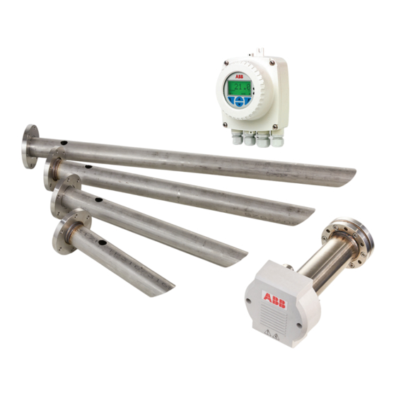
AZ10 oxygen analyzer
The AZ10 is the latest in a long line of high-quality
combustion gas analyzers from ABB. The probe,
based on a zirconium oxide cell, is mounted in close
contact with the process. The resulting direct
measurement provides accurate and rapid oxygen
reading for combustion control/optimization and
emissions monitoring purposes.
The AZ10 has been designed for extended periods
of maintenance-free operation. The modular design,
with reduced component count, improves the
reliability and robustness of the system and
simplifies breakdown repair if it occurs.
Kits containing all the parts needed to complete on-
site repairs are available from ABB, ensuring service
personnel can effect repairs quickly and efficiently
at minimum cost.
Superior technology and quality
from the world leader in oxygen
measurement
Measurement made easy
For more information
Further publications for the AZ10 oxygen analyzer
are available for free download from:
www.abb.com/measurement
or by scanning this code:
Links and reference numbers for AZ10 publications
are shown below:
AZ10 oxygen analyzer –
Data Sheet
AZ20 oxygen analyzer –
User Guide
Endura AZ10 oxygen analyzer –
Leaflet
Key specifications at a glance
Search for or click on:
DS/AZ10-EN
IM/AZ20E-EN
LFT/ENDURA/AZ10-EN
Advertisement
Table of Contents

Related Manuals for ABB AZ10


Summary of Contents for ABB AZ10
- Page 1 Introduction For more information — AZ10 oxygen analyzer The AZ10 is the latest in a long line of high-quality Further publications for the AZ10 oxygen analyzer combustion gas analyzers from ABB. The probe, are available for free download from: based on a zirconium oxide cell, is mounted in close www.abb.com/measurement...
-
Page 2: Table Of Contents
AZ10 probe ........ -
Page 3: Health & Safety
A Z 1 0 O X YG E N A N A LY Z E R | C O M B U S T I O N G A S A N A LY S I S | O I/A Z 1 0 - E N R E V. A Health &... -
Page 4: Information On Rohs Directive 2011/65/Eu (Rohs Ii)
• Normal safety precautions must be taken to avoid the possibility of an accident occurring when operating in ABB is committed to ensuring that the risk of any conditions of high pressure and/or temperature. environmental damage or pollution caused by any of its products is minimized as far as possible. -
Page 5: End-Of-Life Disposal
ABB Ltd and its affiliates are not liable for damages and/or losses related to such security breaches, any unauthorized access, interference, intrusion, leakage and/or theft of data... -
Page 6: Mechanical Installation
Details on the probe label are unique to the cell/probe combination the label is attached to and cannot be used to identify any other probe or system. AZ10/33341012E/STD Example code number – Data Sheet (DSAZ10-EN), page 18. Figure 1 Location of probe label... -
Page 7: Siting
1/2 in NPT gland Relays 80 °C (176 °F) AZ10 probe cable (ABB supplied) – max. 100 m (300 ft) –20 °C (–4 °F) * The probe can withstand 35 kPa (5.1 psi) – positive or negative pressure. Pressure compensation is required above 5 kPa (0.7 psi) –... -
Page 8: Overall Dimensions
A Z 1 0 O X YG E N A N A LY Z E R | C O M B U S T I O N G A S A N A LY S I S | O I/A Z 1 0 - E N R E V. A 4 Overall dimensions Dimensions in mm (in) AZ10 probe (1.34) Nominal insertion length 270 (10.63) -
Page 9: Probe Flanges (All Probe Lengths) And Mounting Plates For Standard Probe Flanges
ABB standard flange 160 (6.3) 160 (6.3) 7 (0.27) 16 (0.63) mounting plate Comprising: mounting plate, gasket, 6 each: M6/M10 shakeproof washers, plain washers and nuts 6 M6 studs equispaced on 80 (3.15) PCD Figure 6 ABB standard mounting plate... -
Page 10: Installation
A Z 1 0 O X YG E N A N A LY Z E R | C O M B U S T I O N G A S A N A LY S I S | O I/A Z 1 0 - E N R E V. A 6 Installation General mounting requirements NOTICE... -
Page 11: Threaded Npt And Bsp Mountings
A Z 1 0 O X YG E N A N A LY Z E R | C O M B U S T I O N G A S A N A LY S I S | O I/A Z 1 0 - E N R E V. A Threaded NPT and BSP mountings 3 Apply high temperature jointing compound to the threads WARNING... -
Page 12: Abb Standard Flange Mounting Plate
A Z 1 0 O X YG E N A N A LY Z E R | C O M B U S T I O N G A S A N A LY S I S | O I/A Z 1 0 - E N R E V. A …6 Installation ABB standard flange mounting plate 3 Locate a gasket over the studs on the adaptor –... - Page 13 A Z 1 0 O X YG E N A N A LY Z E R | C O M B U S T I O N G A S A N A LY S I S | O I/A Z 1 0 - E N R E V. A Exit Gas flow Figure 9 ABB standard flange mounting plate...
-
Page 14: Flange-Mounted Installations
Notes the gas flow – see Figure 7, page 10 and Warning (left). • This procedure is for AZ10 probes mounted to customer- 5 Align the bolt holes in the probe intake tube flange with supplied/installed flanges –... - Page 15 A Z 1 0 O X YG E N A N A LY Z E R | C O M B U S T I O N G A S A N A LY S I S | O I/A Z 1 0 - E N R E V. A Exit Gas flow Figure 10 Flange-mounted installations...
-
Page 16: Electrical Connections
Non-AutoCal system • The AZ10 cable carries the screened signal wires and the Maximum cable length – separately screened 90 to 264 V AC heater wires safely. Do probe to transmitter: 100 m (300 ft) not use alternative wires. -
Page 17: Probe Connections, General
A Z 1 0 O X YG E N A N A LY Z E R | C O M B U S T I O N G A S A N A LY S I S | O I/A Z 1 0 - E N R E V. A Probe connections, general Cable glands WARNING... -
Page 18: Cable Preparation - Non-Autocal Systems (Both Ends)/Az10 Probe To Az10 Transmitter
25 to 30 mm (1 to 1.2 in) expose d White/Yellow White/Black White/Orange White/Green Cut PVC outer cable sheath back White/Red 155 mm (6.1 in) – see step 2 White/Blue *Cut back Figure 15 Cable preparation – non-AutoCal systems (both ends)/AZ10 probe to AZ10 transmitter... - Page 19 Connect screen 1 and 2 drains from 14-core cable to the transmitter internal earth stud only – do not connect the drains to the transmitter SCN connector or the transmitter external earth Figure 16 Electrical connections – AZ10 probe to AZ10 transmitter (non-AutoCal systems)
-
Page 20: Cable Preparation - Autocal Systems (Both Ends)/Az10 Probe To Az10 Autocal Unit
25 to 30 mm (1 to 1.2 in) expose d White/Yellow White/Black White/Orange White/Green Cut PVC outer cable sheath back White/Red 155 mm (6.1 in) – see step 2 White/Blue *Cut back Figure 17 Cable preparation – AutoCal systems (both ends)/AZ10 probe to AZ10 AutoCal unit... -
Page 21: Az10 Probe To Az10 Autocal Unit
22 for (internal) SV1 (White/Green) T/C + (Green) transmitter connections SV COM (White/Red) T/C – (White) connections SV2 (White/Blue) SCN (Screen) Heater H2 (brown) Heater H1 (blue) (AutoCal systems) Figure 18 Electrical connections – AZ10 probe to AZ10 AutoCal unit... -
Page 22: Cable Preparation - Autocal Systems (Both Ends)/Az10 Autocal Unit To Az10 Transmitter
Screen 2 braid – cut back to leave 25 to 30 mm (1 to 1.2 in) expose d Cut PVC outer cable sheath back 155 mm (6.1 in) – see step 2 Figure 19 Cable preparation – AutoCal systems (both ends)/AZ10 AutoCal unit to AZ10 transmitter... - Page 23 – do not connect it to the transmitter's SCN terminal or transmitter external earth * Connect screen 2 (drain) to the AutoCal unit's outer SCN connector only Figure 20 Electrical connections – AutoCal systems/AZ10 AutoCal unit to AZ10 transmitter...
-
Page 24: Test Gas And Reference Air Connections
In a negative pressure process, air leakage causes high O2 reading errors. Figure 21 AZ10 probe – test gas connection NOTICE • It is preferable to use air (20.95 % O2) as one of the test gases as this is the sensor’s zero point. -
Page 25: Test Gas Supply Configurations - Non-Autocal
A Z 1 0 O X YG E N A N A LY Z E R | C O M B U S T I O N G A S A N A LY S I S | O I/A Z 1 0 - E N R E V. A Test gas supply configurations – non-AutoCal systems NOTICE • If using the ABB-supplied test gas port with standard filter option, the test gas supply must be 3 to 3.5 l/min (6.354 to 7.413 scfh). -
Page 26: Schematic - Autocal System
Test gas 1 Test gas 2 Output signals Relays ABB 14-core cable/transmitter to AutoCal unit (length coded option) Maximum combined cable length (14 -core cable + 6-core cable: 100 m [328 ft]) Figure 24 Schematic, AZ10 transmitter to AutoCal unit to probe... -
Page 27: Test Gas Configurations - Autocal Systems With
AZ10 probe Non-return Non-return valve valve AZ10 AutoCal unit AZ10 AutoCal unit Test gas supply: restrictor in Autocal Test gas supply: restrictor in Autocal unit limits flow to 2.2 l/min (4.662 scfh) unit limits flow to 2.2 l/min (4.662 scfh) -
Page 28: Test Gas And Reference Air Supply Configurations - Autocal Systems Without Restrictors
AZ10 probe AZ10 probe Non-return Non-return valve valve AZ10 AutoCal unit AZ10 AutoCal unit Test gas supply: 1 l/min (2.118 scfh) Test gas supply: 1 l/min (2.118 scfh) ABB flowmeter adjusted ABB flowmeter adjusted to 1 l/min (2.118 scfh) STP to 1 l/min (2.118 scfh) STP... -
Page 29: Preparation And Setting Up Test Gases
A Z 1 0 O X YG E N A N A LY Z E R | C O M B U S T I O N G A S A N A LY S I S | O I/A Z 1 0 - E N R E V. A 9 Start-up and operation Preparation and setting up test gases The AZ10 oxygen analyzer should now be ready to commission – refer to the transmitter User Guide (IM/AZ20E-EN). CAUTION... -
Page 30: System Specification
< ±1 % of reading or 0.05 % O , whichever is the greater, (flange pressure ratings do not apply) based on a nominal range of 0.01 to 25 % O • ABB standard flange Drift Probe body material • < ± 1 % maximum % O... -
Page 31: Transmitter Specification
A Z 1 0 O X YG E N A N A LY Z E R | C O M B U S T I O N G A S A N A LY S I S | O I/A Z 1 0 - E N R E V. A 12 Transmitter specification Transmitter enclosures Analog outputs... - Page 32 • FDT v1.2.1 compliant Isolation • Works with FDT framework packages Not isolated from each other or from (for example, ABB Asset Vision Basic) the microprocessor circuitry Input functions Compliant with suitable framework tools • Automatic calibration start on falling edge...
-
Page 33: Accessories And Spares
DIN 65 AZ100095 DIN 80 Adaptor AZ100096 2 in NPT AZ100097 2 in BSP AZ100098 Mounting plates for ABB standard flange Endura AZ10 AutoCal unit (without test gas restrictors) AZ250098 AZ250096 Endura AZ10 AutoCal unit (with test gas restrictors) AZ250099 AZ250097... -
Page 34: Spares
A Z 1 0 O X YG E N A N A LY Z E R | C O M B U S T I O N G A S A N A LY S I S | O I/A Z 1 0 - E N R E V. A …13 Accessories and spares Spares Part number... - Page 35 A Z 1 0 O X YG E N A N A LY Z E R | C O M B U S T I O N G A S A N A LY S I S | O I/A Z 1 0 - E N R E V. A Acknowledgments HART is a registered trademark of the FieldComm Group.
- Page 36 We reserve the right to make technical changes or modify the contents of this document without prior notice. With regard to purchase orders, the agreed particulars shall prevail. ABB does not accept any responsibility whatsoever for potential errors or possible lack of information in this document.
Need help?
Do you have a question about the AZ10 and is the answer not in the manual?
Questions and answers