
Related Manuals for Steinsvik Orbit-3100

Summary of Contents for Steinsvik Orbit-3100
- Page 1 User manual Camera System Steinsvik AS Rundhaug 25, 5563 Førresfjorden, Norway | +47 52 75 47 00 | post@steinsvik.no | www.steinsvik.no...
- Page 2 Rev: Rev. date: By (initials): Edits: A1 10.04.2018 Created A2 20.06.2018 IDFR Added components A3 04.07.2018 IDFR Updated A4 03.09.2018 IDFR Updated spare parts A5 23.11.2018 IDFR Updated with Bracket V-clamp assy chap. 4.6 and 5.2.2 A6 10.12.2018 IDFR Updated maintenance chapter A7 21.01.2019 IDFR Updated information regarding Orbit-310 and maintenance...
-
Page 3: Table Of Contents
TABLE OF CONTENT Introduction ............................5 Symbols ............................ 6 Disclaimer ............................6 Safety ............................... 7 Warranty limitations ........................7 Waste information ........................7 Assessment of escape risk ....................... 8 Technical description ........................9 Underwater camera ......................... 10 Surface camera ........................11 PSU ............................ - Page 4 Maintenance ........................... 35 Routine inspection and periodic maintenance ................ 35 Larger reparations and modifications ..................36 Troubleshooting and correction of errors ................36 Link to troubleshooting for camera system ................37 Storing, preservation and maintenance .................. 37 Spare parts ............................. 38 Underwater camera .........................
-
Page 5: Introduction
INTRODUCTION This manual presents the installation, use and maintenance of the complete Steinsvik AS camera system with associated components. Consult the NeoVision or Vision user manual for the complete description of navigation and configurations. -
Page 6: Symbols
Warning – may lead to personal injury DISCLAIMER Every care has been taken by the staff of Steinsvik AS in compilation of the data contained herein and in verification of its accuracy when published, however the content of this training manual is subject to change without notice due to factors outside the control of Steinsvik AS and this manual should therefore be used as a guide only. -
Page 7: Safety
SAFETY Warranty limitations Warranty according to quote. Waste information PSU, winch and camera house are classified as E-waste Camera house consist mainly of POM, with small amounts of stainless steel. Orbit-bracket for ring, mast and winch bracket Bolts, nuts, screws and washers. The underwater camera with depth sensor contains a small amount of glycol. -
Page 8: Assessment Of Escape Risk
Assessment of escape risk A Steinsvik AS camera system will, under normal working conditions, not pose a risk of escape when it is being used in a cage at a fish farm. The camera system does not consist of any parts that may, under normal conditions, cause damage to the net, ropes or any other parts of the plastic or steel cage construction. -
Page 9: Technical Description
TECHNICAL DESCRIPTION Steinsvik AS camera system is an advanced surveillance system to control the feeding of fish in aquaculture and for general inspection of fish in cages. The camera system consists of: Underwater camera Surface camera Multiwinch Bracket for ring... -
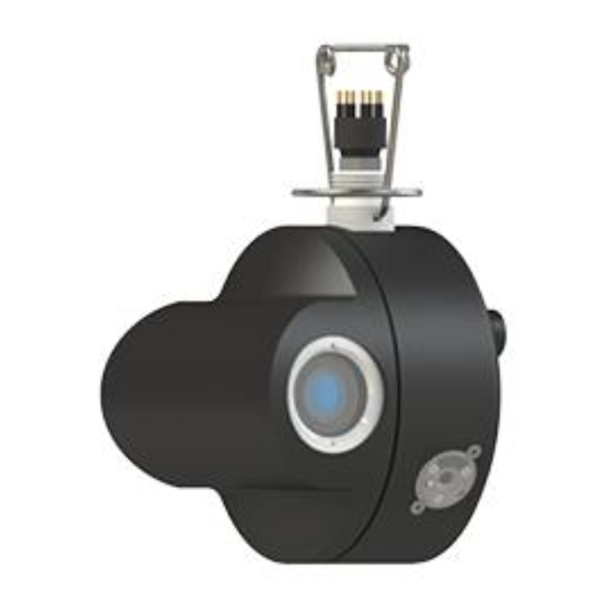
Page 10: Underwater Camera
Figure 1 shows the different models and what sensors they are equipped with. The Orbit-3100 is eqipped with both a temperature and depth sensor, however these sensors will only be available through a software update. This way you do not have to send the camera to service to receive this update. -
Page 11: Surface Camera
Surface camera Orbit-200B and Orbit-210 surface camera is mounted on the same aluminium pipe as the PSU on the cage. The camera is designed as an underwater camera and is therefore waterproof and made from corrosion resistant material. The camera is intended for permanent installation. Figure 2 Orbit-200 Table 2 Specifications Orbit-200B and Orbit-210 Orbit-200... -
Page 12: Psu
The cameras are primarily powered and controlled by the PSU at the cage. In addition, the Orbit-3100, Orbit-3300 and the Orbit-3500 can be controlled from the control system KB-6000, which is connected to 230 VAC and conveys low current and control signals to the connected units. The same cameras can also be connected to the MB-3000 portable control unit which have a built-in screen, joystick and 12 V power to the camera. -
Page 13: Multiwinch
Multiwinch The Multiwinch is mounted on the cage with the Orbit – Bracket for ring and is controlled by the PSU via a control desk or a computer with the camera software installed. The winch is connected to the PSU with its own cable. -
Page 14: Orbit-Bracket For Ring
Orbit-bracket for ring It is possible to connect the PSU, antenna and Multiwinch to the Orbit-bracket for ring. See chapter 5.2.1 for a description on how to install the bracket for ring. Orbit-bracket for ring is delivered with a large and a small bottom mounting bracket to accommodate most of the cages in today’s market. -
Page 15: Antenna And Mast
Antenna and mast The antenna sends data from the PSU to the barge. The sticker on the antenna must face the receiving antenna placed on the barge. For more information regarding mounting and installation, see next chapter. For wireless facilities, the antenna is attached to the aluminium pipe on arrival. For fibre facilities the same aluminium pipe is used for mast to attach the fibre equipment. -
Page 16: Strain Relief
Strain relief The strain relief is delivered with all PSU’s and is used with the fibre cables. It is normally padded before use. Figure 9 Strain relief Figure 10 Padded strain relief Table 8 Specifications strain relief Specifications Material Aluminium and stainless steel Weight 1,5 kg Pulley for camera rope... -
Page 17: Pulleyblock 18 Mm
Figure 12 Pulleyblock 4.11 Camera cable Steinsvik’s camera cable transfer all signals from the PSU to the camera. The cable can be delivered in many different lengths, depending on what is required at the locations. It is delivered either as a blue cable or a black cable where the black cable is enhanced with Kevlar on the outside, while the blue is not enclosed in Kevlar. -
Page 18: Surveillance Camera
4.13 Surveillance camera Steinsvik also supplies several surveillance cameras meant for surveillance at the barge. The Orbit-351 and the Orbit-310 are reliable cameras that provides good visibility on the facility and specific parts of the facility. 4.13.1 Orbit-310 With careful installation of the Orbit-310, you will gain maximum advantage of the camera. The camera can easily be controlled with a gamepad and has an excellent zoom. - Page 19 4.13.2 Orbit-351 The Orbit-351 Stationary Camera is a great tool to help maintain the safety of the crew in areas with less activity, while at the same time having full monitoring of the spaces on the barge you may want. This camera can also be used for monitoring the amount of feed in the silo.
-
Page 20: Fibre Receiver Cabinet
4.14 Fibre receiver cabinet The Orbit-502 IP Receiver cabinet is the receiving cabinet for fibre installations on the barge. The cabinet receive and transmit the signals given from the gamepad to the camera. It can be connected to dome cameras and has the possibility of connecting to sensors. The sensors are not included in the standard delivery and must be ordered separately. -
Page 21: Protection Cabinet For Psu
4.16 Protection cabinet for PSU Figure 17 Protection cabinet for SS PSU Table 15 Specifications Protection cabinet Specifications Material Stainless steel Weight 18,42 kg Dimensions (WxHxD) 466,20 x 649 x 273 mm Steinsvik AS also delivers protection cabinets for plastic PSU’s. -
Page 22: Preparation And Installation
When reinstalling the equipment, (new generation) it is important to ensure that the installation and equipment are in accordance with specifications provided by Steinsvik AS. The use will not cause any contamination of fish. Antenna −... - Page 23 Insert the supplied bolt, washer and locking pin so that the bracket cannot fall off. The mounting bracket goes around the support rail (picture). Fasten this with a M10x20 bolts in the top hole (on both sides). In the bottom hole (on both sides) the M10x30 bolts and M10 nuts are fastened.
- Page 24 5.2.2 Mounting Orbit-Bracket for ring with V-clamp Place the bracket over the top ring of the cage. Insert the supplied bolt, washer and locking pin so that the bracket cannot fall off. The mounting bracket goes around the support rail (picture). Fasten this with a M10x20 bolts in the top hole (on both sides).
- Page 25 Bring the clamp up to the support rail. Fasten it with the supplied locking bolt, washer and locking pin through the bracket and clamp (see picture). Depending on the size of the support rail, the locking bolt is placed in the hole which fits the best on the bracket Adjust the size of the clamp so that it holds the Orbit-bracket in place by turning the nut on the right side on the clamp (the white nut in the illustration above).
-
Page 26: Mast/Alu Pipe
Mast/Alu pipe 5.3.1 Wireless installations Fasten the aluminium pipe into the 40 mm pipe on The mast is supposed to rest on the bolt at the the Orbit-bracket for ring. bottom of the 40 mm pipe. Secure it with a set screw (DIN 912 M8x16). -
Page 27: Psu/Protection Cabinet
PSU/Protection cabinet Fasten the PSU to the mast, as high up as possible. Attach the four nuts to the backside of the PSU. If an extra protection cabinet is used, place the PSU into the cabinet before mounting it on the mast. Remember to secure the protection cabinet with an extra bracket so that there is a total of 6 nuts fastened on the backside. -
Page 28: Winch And Winch Rope
Winch and winch rope Place the washer for the winch bolt on top of the attachement point for the winch on the Orbit bracket for ring. Slide the winch over the washer. Attach the bolt. The winch should be able to rotate to both sides. -
Page 29: Rope And Strain Relief
− Attach the strain relief to the handrail via the pulley. − Attach the counterweight to the end of the strain relief and lower it into the sea. Steinsvik AS recommend fastening a safety rope to the counterweight. − Wind the winch rope onto the winch. -
Page 30: Underwater Camera
Underwater camera − Connect everything else before connecting to 230 V. − Disconnect power supply before disassembly. − Inspect for any damage on the metal hoop on the camera before submerging the camera − When the camera contact is disconnected from the rest: remove all sand and growth with isopropyl alcohol and apply Molykote before reassembly. - Page 31 The camera rope is supposed to tensions relieve the camera cable so that both the camera and the camera cable is lifted by the rope (from the Multiwinch). − Lower the camera into the sea and wind the camera cable out in the cage. −...
-
Page 32: Surface Camera
Surface camera Attach the Orbit-200B/210 to the top of the mast at the cage. Place the camera in the direction you want to look. On PSU’s supporting surface cameras: connect the camera cable to the «Multi contact» marked with a green circle on the PSU. Surveillance camera −... -
Page 33: Operating Instructions
OPERATING INSTRUCTIONS Multiwinch/underwater camera The camera system is primarily controlled via the NeoVision or Vision software on a computer or a control desk located on the barge or land base. It is also possible to operate the winch from the cage edge, this makes accessing the camera for maintenance/inspection purposes easier. - Page 34 Figure 22 Gamepad Figure 23 Gamepad backside...
-
Page 35: Maintenance
MAINTENANCE Routine inspection and periodic maintenance Table 16 Routine inspection and periodic maintenance Interval Component Description Check for any icing during the winter Entire system (incl. cables months. Remove ice if found on any and antennas) equipment. Check that all screws for lids are fastened Screws on the PSU/Winch and in place Wipe around cables to prevent mussels from... -
Page 36: Larger Reparations And Modifications
PSU can be sent in for service every other generation. Calibration and/or change of oxygen film on the underwater camera must be sent in to Steinsvik AS when needed (damage). Estimated lifetime without damage is 5 years. -
Page 37: Link To Troubleshooting For Camera System
3. Rinse, clean and wipe dry all cables to remove any salt residues. Check for wear and tear, change if necessary. Coil the cables together for storage. 4. Clean the camera to remove all growth. Steinsvik AS recommend sending the camera for service after every generation (change gaskets, calibration of sensors). -
Page 38: Spare Parts
SPARE PARTS Underwater camera Orbit-3100: 417854 Orbit-3300: 406632 Orbit-3500: 410481/420590 Orbit-3400: 430463 Orbit-3600: 421021 Product Pos. nr. Description Amount number Silicone oil Membrane 406293 Obrit-200 (411340) and Orbit-210 (430755) Product Pos. nr. Description Amount number ISO 4762 M6 x 40 A4 Washer DIN 125 - B 6.4 -... -
Page 39: Multiwinch (100069)
Multiwinch (100069) Item No. Product No. Qty. Product Washer for shaft Bolt for winch 405571 Split pin 401670 Hanger 401311 403620 100m Rope 3 mm nylon Pan head cross recess screw M6x16 Pan head cross recess screw M4x16 Plain washer M6 Plain washer DIN 9021-4.3 Wing nut M4 401611... -
Page 40: Orbit-Bracket For Ring (405461)
Orbit-Bracket for ring (405461) Product Pos. nr. Description Amount number Mounting Bracket (small) 417314 Mounting bracket (large) 420304 12mm locking bolt 196mm 405721 12mm locking bolt 237mm 418684... -
Page 41: Orbit-Bracket For Ring With Clamp (V-Clamp) (442778)
Orbit-bracket for ring with clamp (V-Clamp) (442778) Pos. nr. Beskrivelse Varenummer Antall 12mm locking bolt 196mm 405721 12mm locking bolt 237mm 405830 V-Clamp Assy 420297 Mounting Bracket (small) 417314 Mounting bracket (large) 420304 Bolt set 442197... -
Page 42: Antenna (411859)
Antenna (411859) Product Pos. nr. Description Amount number Top cover 405259 O-ring 77x4,0 405263 Antenna 411156 Cable (complete) 2,5m 420441 Strain Relief (420438) Product Pos. nr. Description Amount number DIN EN ISO 10511 - M10 DIN 912 M10 x 80 DIN 912 M8 x 16... -
Page 43: Orbit-310 (410478)
Orbit-310 (410478) Product Pos. nr. Description Amount number Countersunk flat head cross recess screw ISO 7046 M8x30 Baseplate 410982 Washer DIN 129-9 Prevailing torque nut DIN EN ISO 7042 M8 Cable 30m 430338... -
Page 44: Orbit-Psu Stainless Steel
✓ Software NeoVision6.2 and newer ✓ ✓ ✓ ✓ ✓ Vision ✓ ✓ ✓ ✓ Orbit-3000 ✓ ✓ ✓ ✓ Orbit-3100 ✓ ✓ ✓ ✓ Orbit-3300 ✓ Orbit-3400 Supported by ✓ ✓ ✓ ✓ Orbit-3500 Camera ✓ Orbit-3600 ✓ ✓... - Page 45 ✓ ✓ ✓ Software NeoVision6.2 and newer ✓ ✓ ✓ ✓ ✓ ✓ Vision ✓ ✓ ✓ Orbit-3000 ✓ ✓ Orbit-3100 ✓ ✓ ✓ Orbit-3300 ✓ ✓ ✓ Orbit-3400 Supported by ✓ ✓ ✓ Orbit-3500 Camera ✓ ✓ ✓ Orbit-3600 ✓...
Need help?
Do you have a question about the Orbit-3100 and is the answer not in the manual?
Questions and answers