Table of Contents
Advertisement
Advertisement
Table of Contents

Related Manuals for Zenitel Phontech ICS 6200

Summary of Contents for Zenitel Phontech ICS 6200
- Page 1 INSTALLATION MANUAL ICS 6200 MARITIME: COMMUNICATION SYSTEMS...
- Page 2 Standards The equipment is tested to the following product standards: EMC: EN60945 (2002), EN61000-4-2, EN61000-4-3, EN61000-4-4, EN61000-4-5, EN61000-4-6, EN61000-4-11, IEC60092-101 Environmental: EN60945 (2002), EN60068-2-1, EN60068-2-1, EN60068-2-2, EN60068-2-6, EN60068-2-30, EN60068-2-52 Ingress protection: IEC60529 Compass safe distance: EN ISO 694 Health and Safety: EN60950, CSA-C22.2 60950 For an updated list of approvals and statements of conformity, these are available from:...
- Page 3 Amendment Record INIT DATE CHAPTERS VERSION REASON FOR CHANGE H.S. 24.05.13 Initial release Initial K.A.T. 01.09.14 Updated manual for 1.2 firmware release. relea K.A.T 10.10.14 Added warranty and utilization section. K.A.T 11.05.15 Updated for trunk parking functionality. K.A.T 26.04.16 Added information about Snom 710. 26.09.2016 General Update, new enclosures, new teleph.
- Page 4 The information in this book has been carefully checked and is believed to be accurate. However, no responsibility is assumed for inaccuracies. Zenitel AS reserves the right to make changes without further notice to any products or modules described herein to improve reliability, function or design. Zenitel AS does not assume any liability arising out of the application or use of the described product.
-
Page 5: Table Of Contents
TABLE OF CONTENTS SYSTEM DESCRIPTION ................ 1-7 ......................1-8 AJOR FUNCTIONS 6200 ....................1-9 ECHANICAL LAYOUT 6200 .................... 1-9 LECTRICAL CONNECTIONS 6200R ..................... 1-10 ECHANICAL LAYOUT 6200R ..................1-11 LECTRICAL CONNECTIONS 1.5.1 AC-DC ........................1-11 VERSION 1.5.2 AC-AC ........................1-11 VERSION ........................ - Page 6 2.3.4 ........................2-28 OMMON ASKS 2.3.5 ......................2-51 OMMON ASKS 2.3.6 ......................... 2-72 ROUBLESHOOTING ..................... 2-75 RONT ANEL ANUAL 2.4.1 LED I ........................2-75 NDICATIONS 2.4.2 ......................2-75 RONT ANEL ISPLAY 2.4.3 ......................... 2-75 IRST IZARD 2.4.4 ..........................2-76 ENUS ....................
- Page 7 4.2.6 PHONTECH 7211, WP ..............4-159 UNIT W HANDSET 4.2.7 PHONTECH 7212, WP ..............4-164 UNIT WO HANDSET 4.2.8 PHONTECH 7223, ..............4-169 CONSOLE MOUNTED UNIT 6035 ................4-175 HEADSET WITH HOOKSWITCH ANALOG TELEPHONES ..............5-176 GIGASET DA710 ......................5-176 PHONTECH 5113/5123 ............
- Page 8 Returned products in lack of such reference, will not be accepted by Zenitel and returned to Buyer at Buyer’s cost. g) The cost of the return shipment is to be covered by the Buyer. Zenitel will cover the cost of shipment for replacement parts.
-
Page 9: System Description
UTILIZATION: This equipment is not to be disposed in normal waste, but be handled in accordance with applicable waste disposal regulations in the country where the equipment is used. 1 SYSTEM DESCRIPTION The Integrated Communication System Phontech 6200 is designed to meet the requirements for internal communications and shore connections on board ships. -
Page 10: Major Functions
1.1 MAJOR FUNCTIONS The major functions of the Phontech 6200 system includes: • PABX operation. • Intercom operation. • Public address. • Access to external systems and nets. • Cost effective modular design. • Flexible dual power supply configuration. • Flexible Numbering plan •... -
Page 11: Mechanical Layout 6200
1.2 MECHANICAL LAYOUT 6200 1.3 ELECTRICAL CONNECTIONS 6200 p/n 4000087299 v.I Page 1-9... -
Page 12: Mechanical Layout 6200R
1.4 MECHANICAL LAYOUT 6200R p/n 4000087299 v.I Page 1-10... -
Page 13: Electrical Connections 6200R
1.5 ELECTRICAL CONNECTIONS 6200R 1.5.1 AC-DC VERSION 1.5.2 AC-AC VERSION p/n 4000087299 v.I Page 1-11... -
Page 14: Stacking
1.6 STACKING Multiple Phontech 6200 units communicate using the Ethernet ports LAN1 (25) and LAN2 (26). The LAN1 and LAN2 ports are connected internally by a built-in Ethernet switch. Interconnecting 6200 units is done by connecting Ethernet patch cables between the LAN ports. Three topologies are possible. -
Page 15: Ring Topology, Which Has The Added Benefit Of Redundancy
1.6.3 RING TOPOLOGY, WHICH HAS THE ADDED BENEFIT OF REDUNDANCY The Ethernet connections have a maximum segment length of 100m. If longer segments are required, repeaters or media converters can be used. This allows for physical separation of multiple Phontech 6200 units within a single system. 1.7 RACK MOUNTING 6200 variant: It is recommended to arrange the Phontech 6200 units in pairs with a patch panel in between for... -
Page 16: Installing Line Boards In The Phontech 6200/6200R
1.8 INSTALLING LINE BOARDS IN THE PHONTECH 6200/6200R The line boards are installed on the carrier board inside a Phontech 6200/6200R unit. The line boards are color coded. Up to 6 line boards can be installed in any order on the carrier board in 6200. p/n 4000087299 v.I Page 1-14... - Page 17 Line interface board connectors relates to front panel ports in the following way: Line interface board Ports 1 - 4 5 - 8 9 - 12 13 – 16 17 – 20 21 – 24 Also in 6200R 6 line boards can be installed in any order on the carrier board. Line interface board connectors relates to line interface board in the following way: Line interface board Ports on interface board...
-
Page 18: Fxs Board
Line impedance according to ES 203-021 The FXO line is connected to terminal 4 and 5 on the RJ-45 jack 1.11 UPN BOARD The UPN line board supports 4 lines of Zenitel Digital Intercom (61xx) lines. Line voltage +37VDC Line impedance... -
Page 19: E&Mboard
1.12 E&M BOARD The E&M board is typically used to connect systems like PA/GA and VHF/UHF radio paging. It has two audio/key inputs and two audio/key output. The audio inputs can be either line level or microphone level with AGC. The keying input accepts dry closing contacts. -
Page 20: 6200/6200R Power Terminal Module
6200R variant: The inputs are connected to odd-numbered ports, while outputs are connected the next even numbered port. The audio is connected to lines A/B, while key is connected to lines C/D on the 4000019813. See chapter 3.2.1.3.1 for more information. 1.13 6200/6200R POWER TERMINAL MODULE When the Phontech 6200 or Phontech 6200R is installed in a cabinet, a common power terminal module is fitted, for easy termination of the required power supplies, as well as the power failure... -
Page 21: Installation
Zenitel strongly recommend the use of junction boxes for the external cable distribution. 2.1.1 CABLE TERMINATION First, ensure that the cable to be used is according to the Zenitel specifications. See 2.1.8 and 2.1.9 for more details. 2.1.2 GLANDS The cables enter weather-proof units by means of cable glands. -
Page 22: Cable Requirements For Ethernet
Power cables: 1 pair + Ground 2.1.9 CABLE REQUIREMENTS FOR ETHERNET The Ethernet cables must be of specification category 5e UTP or better. Zenitel recommends using the TIA/EIA-568-B.1-2001 termination scheme. The maximum length of each segment must be less than 100m. -
Page 23: Commissioning Test
2.1.11 COMMISSIONING TEST The Phontech 6200 shall be configured according to the customer requirement. Tests to be performed: • Handbook is delivered and available for commissioning • Check the installation according to installation instructions Using the configuration as reference, for each extension check: •... - Page 24 In the above example diagram, there are three 6200 units arranged in order, as well as several VoIP telephones which receive an IP address from 6200-unit number 1 via DHCP. By default, each 6200-unit will route external traffic via 172.16.0.254. Also by default, DNS requests will be sent to 172.16.0.254.
-
Page 25: Installing The Phontech 6200 In A Separate Network
We recommend installing the Phontech 6200 system in a physically separate network or in a separate 802.1q VLAN. 2.2.3 INSTALLING THE PHONTECH 6200 IN A SEPARATE NETWORK Using a physically separate network is the simplest method of installing a Phontech 6200 system. It allows you to isolate the PBX from the rest of your network at the cost of separate infrastructure. -
Page 26: Installing The Phontech 6200 In A Separate 802.1 Qvlan
In the above example, three Phontech 6200 units are connected in a redundant ring while being separate from the main network. Please note that this also implies separate cabling for the VoIP telephones present. 2.2.4 INSTALLING THE PHONTECH 6200 IN A SEPARATE 802.1Q VLAN It is also possible to install the Phontech 6200 system in a network separated by using 802.1q VLANs. - Page 27 In this approach, the end-point must be VLAN-aware in order to receive any of the tagged traffic. This could be used to share a port between a computer and a VoIP telephone. For more complex scenarios, please contact Zenitel for a feasibility study. p/n 4000087299 v.I Page 2-25...
-
Page 28: Using 802.3Af-2003 Poe For Voip Telephones
2.2.5 USING 802.3AF-2003 POE FOR VOIP TELEPHONES Power over Ethernet (“PoE”) allows units which supports it to replace the usual “wall wart” power supplies that are commonly used for most electrical products. To take advantage of this, a PoE- capable switch must be used, the end-point must support PoE and the length of the cabling between the two may not exceed 100 meters, as per 802.3af-2003. -
Page 29: Configuration Application
2.3 CONFIGURATION APPLICATION 2.3.1 PREREQUESITES 2.3.1.1 Requirements The Phontech 6200 Configuration Application requires as a minimum the following: Windows Vista SP1, Windows 7, Windows 10 or later. At least 1 GHz CPU speed. At least 512MiB of RAM. At least 500MiB of free disk space. 100 Mbit/s Wired Network Connection. -
Page 30: Common Tasks
2.3.4 COMMON TASKS 2.3.4.1 Connecting to a Phontech 6200 Network In order to connect to and configure a Phontech 6200 system, you must connect your computer to the Phontech 6200 network. Make sure that your computer is set up to automatically acquire network addresses, and connect your computer to one of the LAN ports on the front of the 6200. - Page 31 2.3.4.2 Making Changes and Saving Them When making changes to the configuration in the configuration application, it is important to note that the changes are not applied to the Phontech 6200 system until you choose to send them. Sending your changes can be done via the toolbar, or via "File -> Send". Figure 2-4 - Send Configuration Figure 2-5 - Send Configuration in File-menu p/n 4000087299 v.I...
- Page 32 The configuration can also be saved to disk using the regular "Save" or "Save as..." commands. Note that this does not imply the "Send" operation - this must be performed separately. Figure 2-6 - Save Configuration Please note that if you have just set up users on a new Phontech 6200 Unit or a unit that you have just installed new line interface boards on, the configuration application will have to perform some more intrusive set up procedures, which will cause any ongoing calls on the unit to be terminated.
- Page 33 2.3.4.4 Adding Users To add users to the system, please use the Add Multiple Users Wizard. It can be started from the start view or from the menu bar under "Users". Figure 2-9 - Add Users Once you have started the wizard, you will be greeted by an introduction describing the wizard you have just started.
- Page 34 Analog (FXS): The "regular" station interface. Requires an unused port on a FXS line interface. Please note that Analog telephones do not support paging or alert groups. Digital (UpN): The Zenitel proprietary digital interface. Requires an unused port on an UpN line interface.
- Page 35 Given that one or more of the new users are of the FXS or UpN type, you must now choose which ports to use. You will be presented with a visual representation of the Phontech 6200 system, where you can pick the desired port on the desired unit. The ports to select are determined by the type of users you have created.
- Page 36 Figure 2-12 - Add Users: Adding SIP and Snom 300 Users Additionally, if one or more of the new users are of a Snom 300 or SIP type, one may select which 6200 unit they shall be registered on. The configuration application will automatically select this, based on how many VoIP phones are registered on each unit already, but this can be changed here.
- Page 37 Figure 2-13 - Add Users: Registration Info for SIP and Snom 300 2.3.4.5 Managing Users with Classes A class is a collection or set of users that may share some properties. It is an optional feature that may be used to simplify certain parts of the configuration of large systems. p/n 4000087299 v.I Page 2-35...
- Page 38 Figure 2-14 - Adding Classes Consider a system where a subset of users - let us call them "Officers" – have access to a number of features - such as paging groups, dialing out over a trunk interface or high priority access to certain users.
- Page 39 To add classes, please use the "Add Classes Wizard". Figure 2-15 - Adding Classes p/n 4000087299 v.I Page 2-37...
- Page 40 To assign class membership to users, you may use the "User Properties" or "Class Properties" dialogs for existing users, or select the desired class when adding new users. Figure 2-16 - Adding Members to a Class Using "Class Properties” p/n 4000087299 v.I Page 2-38...
- Page 41 Figure 2-17 - Assigning Class Membership in the “User Properties” Window 2.3.4.6 Adding a Group Groups provide different functionality on a set of users that are members of the group. The functionality differs on the type of group: Call Group: When the group extension is dialed, the group will call all of its members simultaneously.
- Page 42 To add a group, start the relevant group type wizard. Figure 2-18 - Adding an Alert Group The first step is to enter a name and optionally a description for the group. Unless the group is an Alert group, you will also have to enter an extension for the group. If the group is an Alert group, we will have to select an unused E&M pair to be used as the source of the alert.
- Page 43 Figure 2-19 - Selecting the Input for the Alert Group We will then select the members of the group. You may select classes, individual users and, in some cases, even other groups. If the group you are adding requires paging functionality, only uses which support this is listed.
- Page 44 Figure 2-20 - Adding members to the Alert Group. Note that only users which support paging are listed Please note that the order of the members is significant in the Call Hunting group, and may be adjusted using the arrow buttons. For all other groups, the order of the members is insignificant. p/n 4000087299 v.I Page 2-42...
- Page 45 Figure 2-21 - Arranging members in a Hunting Group Once the members have been added, all we need to do is verify that the information we entered is correct. p/n 4000087299 v.I Page 2-43...
- Page 46 Figure 2-22 - Verifying a new Call Group 2.3.4.7 Adding a Trunk Line A Trunk Line allows you to connect your Phontech 6200 system to another PBX or the public telephone system. Different methods may be used to dial out over the trunk or receive calls from the trunk.
- Page 47 Figure 2-23 - Adding a Trunk Line Figure 2-24 - Selecting the Type of the new Trunk Line p/n 4000087299 v.I Page 2-45...
- Page 48 If the trunk type is SIP client, you will have to enter the IP-address or hostname of the provider, as well as the username, password and realm as supplied by your provider. The 6200 drop down defines which 6200 unit in the network the Trunk Line shall be added to. The "Behind NAT"...
- Page 49 extension and enter the parking room number to retrieve the call. This extension number is configured in the Phontech 6200 System Settings and if it is already configured it will be displayed below the checkbox for the parking option. This option can also be changed from the “Incoming Call Actions”...
- Page 50 Figure 2-27 - Select which users who should be reachable from incoming calls We must also define the outgoing behavior. This can either be "Prefix and dial out extension" - which allows your users to dial out using the trunk with both a prefix and a dial out extension, "Decided by extension length"...
- Page 51 Figure 2-28 - Outgoing calls behaviour Unless dialing out over the trunk is disabled, you must now select the dial out extension, and optionally prefix. If "Direct Inward Dialing" was selected during choosing the incoming actions, you must now supply your DID-prefix and fallback number in case we do not have a correct prefix to send.
- Page 52 Figure 2-29 - Supply the extension or prefix number to use Finally, please verify that the information is correct. Figure 2-30 – Verify trunk settings p/n 4000087299 v.I Page 2-50...
-
Page 53: Less Common Tasks
To be able to use SIP telephone or Snom 300 telephones in your Phontech 6200 system, you have to have a SIP license installed. This license will be provided to you by Zenitel AS. To check the current status of your SIP license you can go to the "Help -> Info" item from the menu bar. If you click the "Licenses"... - Page 54 Figure 2-32 - License Information To acquire a new license from Zenitel AS or upgrade an old one you can use the "Request License Quote" dialog. This can be found under the "Help -> Request License Quote" menu. Figure 2-33 - Request License Quote Menu Item Fill out the dialog to request the number of SIP licenses you want and click the "Save"...
- Page 55 Figure 2-34 - Request License Quote Dialog To make sure the license will be correct make sure all Phontech 6200 Units have been connected to the system When you receive a license file you must import it to the configuration. Be sure to keep this license file safe as you will need it again if you want to create a new configuration from scratch for this system.
- Page 56 If the license file you selected was valid you will be notified about this and you can check the status of your license under "Help -> Info" as explained earlier. Figure 2-36 - License Import Successful 2.3.5.2 Access Control In order to restrict access to certain resources, it is possible to set up Access Control via the configuration application.
- Page 57 Figure 2-38 - Restricting access to a Group p/n 4000087299 v.I Page 2-55...
- Page 58 Figure 2-39 - Viewing the Access Control settings of a Class Figure 2-40 - Restricting Access to a User p/n 4000087299 v.I Page 2-56...
- Page 59 2.3.5.3 Hotline Hotline mode is the ability of having a telephone automatically dial an extension upon going off hook. It is possible to set up on analog or digital users by using the properties dialog of the user in question and opening the hotline tab. Figure 2-41 - Enabling Hotline for a User Please note that this means that this user may only reach the recipient(s) specified in the hotline tab as he or she may no longer dial extensions.
- Page 60 Figure 2-42 - Enabling High Priority for a User 2.3.5.5 Additional Tools The “Tools”-menu of the configuration application contains several additional tools for configuration and management of the Phontech ICS 6200/6202 and associated phones. These tools are described in the following sections. Figure 2-43 – Tools-menu 2.3.5.1 Modifying Global Snom Settings...
- Page 61 as the volumes of calls in speaker and handset mode. Under the "Other" section you can force the settings for all phones. This will disallow any user to change any of these settings on the phone itself. Figure 2-44 - Changing Global Snom Settings 2.3.5.2 Modifying Global UpN Settings The global UpN settings dialog allows you to change the default settings for the UpN telephones in your system.
- Page 62 All the speed dial buttons can either be pushed once or held down. If the buttons are pushed the calls must be terminated by either by putting the handset back on-hook or pressing the ACT key. If the buttons are held down the call will automatically terminate once the button is released. Figure 2-45 - Changing Global UpN Settings 2.3.5.1 Custom System Sounds The Phontech 6200 system allows you to change some of the default sounds and notifications used...
- Page 63 Figure 2-46 - Custom Sound Files Screen 2.3.5.2 Modifying Phontech 6200 System Settings The Phontech 6200 System Settings dialog allows you to configure certain system-wide features. Among these are the “Time”-settings, “SNMP”-settings and the system wide “Analog Phone” settings. Using this dialog, it is possible to set the time to a specific time zone and to synchronise the time to an external NTP-server.
- Page 64 Figure 2-47 - Phontech 6200 System Settings – Time Settings Figure 2-48 - Phontech 6200 System Settings - SNMP Settings p/n 4000087299 v.I Page 2-62...
- Page 65 To enable version 3 of the protocol, simply select the correct version from the dialog and enter the desired login information. The authentication method, encryption method and security level may be changed from this dialog, but the defaults should suffice for most cases. When in doubt, leave this unchanged. Figure 2-49 - Setting up SNMP Version 3 If you wish to receive traps from the Phontech 6200 system, please enable the checkbox and enter a valid IP-address, optionally followed by a port.
- Page 66 Figure 2-50 - Phontech 6200 System Settings - Analog Phone Settings System wide settings for analog phones are configured in the “Analog Phone Settings” tab. Here the settings for the “Flash” function can be changed. The extension to retrieve calls stored in the incoming trunk line parking lot can be configured from the “Trunk Line Parking Settings”...
- Page 67 Figure 2-51 - Phontech 6200 System Settings - Trunk Line Parking Settings 2.3.5.3 Configuring Billing The Phontech 6202 Billing Unit Settings dialog allows you to configure the storage devices in your network. This is required to make use of call logging functionality. The dialog can be found under the 'Tools' menu.
- Page 68 Figure 2-52 - Phontech 6202 Billing Unit Settings Before any call logging setting can be changed, you must first select a storage unit to be used in the network. This is done in the drop down box in the upper left part of the page view. The other settings can only be changed after this has been done.
- Page 69 Figure 2-53 - New PIN Dialog The web interface for the storage unit can be access by typing the IP address of the storage unit into the address bar of web browser. The address is shown in the drop down where you select the unit to use as your call logging storage device.
- Page 70 Figure 2-54 - Trunk Line Properties Screen There are two other options that can be enabled in the call logging options page. If "Enable pre-paid billing meters" is checked, a user will only be able to make a call if the account he is associated with, either a PIN or the phone itself, must have a pre-paid balance.
- Page 71 load up the configuration from system A and enter the "Migrate Configuration" wizard from the Tools menu. In the Migrate Configuration wizard you are presented with the view of the current system as well as the view of the system in the loaded configuration. The system in the configuration can be seen under "Configured ICSes"...
- Page 72 It is possible to upgrade the firmware of Phontech 6200 units by using the Phontech 6200 Configuration Application and a new firmware file as supplied by Zenitel. You can upgrade the firmware of specific Phontech 6200 units by right clicking on the unit in question in the lower left corner of the application and selecting "Upgrade Firmware".
- Page 73 Figure 2-57 - Information about Current and New Firmware 2.3.5.2 Configuring Conference Rooms Conference Rooms are special extensions where multiple users may engage in conversations together. The Conference Configuration dialog allows you to enable conference rooms and configure the extension used to dial to the conference rooms. Figure 2-58 - Enabling Conference Rooms p/n 4000087299 v.I Page 2-71...
-
Page 74: Troubleshooting
2.3.6 TROUBLESHOOTING In the case that you run into some trouble, this section contains some pointers on how to get some help and how to troubleshoot basic issues. 2.3.6.1 Starting from Scratch with a New Configuration If the configuration you have created does not fit as well as anticipated, it may be easier to restart from scratch. - Page 75 2.3.6.4 Factory Reset This function will revert the Phontech 6200 unit to its factory state, and remove all configuration, databases and settings contained on the Phontech 6200 unit. It is possible to perform this using the front panel display of the Phontech 6200 unit. Once this has been performed, the Phontech 6200 unit reverts to its factory defaults.
- Page 76 Figure 2-61 - Information Window 2.3.6.7 List of allowed separators in names It is possible to use alphanumeric characters for names in the configuration application, in addition to the following separators: '-' (hyphen) ',' (comma) '.' (period) '+' (plus) '&' (ampersand) '#' (hash) p/n 4000087299 v.I Page 2-74...
-
Page 77: Front Panel Manual
2.4 FRONT PANEL MANUAL 2.4.1 LED INDICATIONS There are three LEDs found on the left side of the Phontech 6200 unit, providing different information. From top to bottom, they are the power LED, the info LED and the error LED. Figure 2-62 - Phontech 6200 Front View The power LED will either be red or green, depending on the power supply status of the unit. -
Page 78: Menus
2.4.4 MENUS When running, the display will show the Zenitel logo by default. When this is shown, pressing any of the buttons on the unit will show the menu system. Figure 2-70 - The Zenitel Logo, the Default View You may navigate through the menu system by using the up and down buttons. - Page 79 2.4.4.1 Module Overview Figure 2-71 - Module Overview This screen gives a quick overview of the current state of the line modules installed. If any UpN modules are installed, it is possible to see which ports on the front that have telephones connected. 2.4.4.2 Modules Figure 2-72 - Modules Menu Figure 2-73 - Viewing a Specific Module Position...
- Page 80 Figure 2-77 - Viewing a SIP Extension The SIP menu allows you to see the SIP telephones configured on this Phontech 6200 unit. It will show you the extension the SIP telephones are registered under and if the phone is currently registered.
- Page 81 2.4.4.5.3 Version Figure 2-83 - Version Menu Figure 2-84 - Viewing the Firmware Version The Version menu provides the version and build date of the currently running firmware on this Phontech 6200 unit. 2.4.4.6 Setup 2.4.4.6.1 Adjust Clock and Date Figure 2-85 - Adjust Clock and Date Menu Figure 2-86 - Adjust Clock Figure 2-87 - Adjust Date...
- Page 82 The Mark as Good menu allows you to take a copy of the currently running firmware and configuration and store it as a "Known Good" image in a separate part of the unit. This firmware and configuration can then be restored using the "Revert to Known Good"-menu at a later date. If you choose to create a new "Known Good"...
-
Page 83: Call Logging Web Interface
2.4.4.6.5 Revert to Known Good Figure 2-95 - Revert to Known Good Menu Figure 2-96 - Selecting the Revert to Known Good Menu The Revert to Known Good function allows you to return to a previously set Known Good checkpoint or, if no such point has been created, to the factory defaults. -
Page 84: Public Address In 6200
2.6 PUBLIC ADDRESS IN 6200 An emergency public address functionality can be set up in a Phontech 6200 configuration. This requires an additional power amplifier 1671 (ref. 3.2.1.3.3), a loudspeaker network and two Emergency PA units, 6216 (ref. 8.5). Figure 2-99 The two Emergency PA units 6216’s must be connected and configured to a E&M board (ref. - Page 85 Select E&M line type Figure 2-101 Select E&M port. This port will correspond with specific terminal on the terminal module (ref. ch 3.2.1.3.1) Figure 2-102 Disable incoming calls. Line in level selection is indifferent in this case Figure 2-103 p/n 4000087299 v.I Page 2-83...
-
Page 86: Preparing An Emergency Pa Group
Select a dial out method. As this extension is only meant to open the interface and access the connected amplifier no prefix method is required. Figure 2-104 The system configuration requires a call out extension number. For the Emergency PA functionality, no extension is basically required. - Page 87 As this EMPA group is intended to be accessed by Emergency PA unit 6216 only, no extension is basically required. Select an “fictive” extension number out of the normal range. Figure 2-107 Add the previously prepared Trunk line; “Amplifier 1671 Connection” as a member of this EMPA group.
-
Page 88: Adding A 6216 To An E&Mboard Trunk Line And Access To The Empa Group
2.6.3 ADDING A 6216 TO AN E&M BOARD TRUNK LINE AND ACCESS TO THE EMPA GROUP Add an E&M trunk line for the 6216 Figure 2-109 Select E&M line type Figure 2-110 Select E&M port. This port will correspond with specific terminal on the terminal module (ref. ch 3.2.1.3.1) Figure 2-111 p/n 4000087299 v.I... - Page 89 Select “Call an extension” and “Microphone Mode” Figure 2-112 Add the previously prepared EMPA group “Emergency Public Address announcement” as the incoming call action for this trunk line. Figure 2-113 p/n 4000087299 v.I Page 2-87...
-
Page 90: A Nempa Group Has An Overall Priority In The System And Will Override Any Other Actions
Then at last disable incoming call as this is not an option for the Emergency PA Unit. Figure 2-114 Any more 6216, Emergency PA units is added to access this “Emergency Public Address announcement” group. AN EMPA GROUP HAS AN OVERALL PRIORITY IN THE SYSTEM AND WILL OVERRIDE ANY OTHER ACTIONS. -
Page 91: Phontech 6200 As Pa/Ga Speaker Loop
2.7 PHONTECH 6200 AS PA/GA SPEAKER LOOP The Phontech 6200 system can be configured as a speaker loop for an existing PA/GA system such as MPA 1600. The alarm and PA messages will be administered from the PA/GA system and the phones in the Phontech 6200 system will be used as a speaker loop where the alarm or message will be played. - Page 92 Select the recipients of PA/GA messages and alarms. Note that only Phontech 61xx, 62xx and 72xx stations are supported and high priority stations are not listed in the available list. NOTE: An EMPA group has an overall priority in the system and will override any other actions, so don’t select stations that should be usable during a PA/GA event.
-
Page 93: Adding The Trunk Line Connected To The Pa/Ga System
2.7.2 ADDING THE TRUNK LINE CONNECTED TO THE PA/GA SYSTEM Add an E&M trunk line for the PA/GA system, detailed information can be found in (ref ch 2.3.4.7). Figure 2-120: Adding a trunk line to the PA/GA system Select E&M line type. Figure 2-121: Select line type Select E&M port. - Page 94 Set Incoming action to Call an extension and select Line In Mode as EM Input Mode. Figure 2-123: Select incoming call action Select the group created in (ref ch 2.7.1) as the incoming call handler for the trunk line. Figure 2-124: Select incoming destination Disable the outgoing actions for this trunk line.
- Page 95 Figure 2-125: Disable outgoing actions The setup should now be complete and the configuration should be sent to the Phontech 6200 units by pressing the ‘Send Configuration’ button in the main screen. p/n 4000087299 v.I Page 2-93...
-
Page 96: System Cabinets/Racks And Typical Configurations
3 SYSTEM CABINETS/RACKS AND TYPICAL CONFIGURATIONS 3.1 CONFIGURATIONS FOR 6200 The basic cabinets for the Phontech 6200, ICS system configurations are a range of 4 different mini rack sizes; 9U (4000018934ICS), 16U (4000019835ICS), 25U (4000018936ICS) and 34U (4000018937ICS). A 34U combination rack for ICS and PAGA is also available (4000018937COM). All cabinets/racks are based on the Schroff Novastar series, colour RAL7021 BlackGrey. - Page 97 Layout example (14848-001-ML-04), 2 pcs 6200, 1 LAN Sw; 48 Lines, 24 VoIP. Layout example (14848-001-ML-07) 1 pc 6200; 0 Lines, 48 VoIP. p/n 4000087299 v.I Page 3-95...
- Page 98 Terminal arrangement and connection AC/DC (14848-001-TA-01 / 14848-001-EC-01): AC/AC (14848-001-TA-02 / 14848-001-EC-02): p/n 4000087299 v.I Page 3-96...
- Page 99 For further connection details each system is supplied with a project dependent cable plan. This is during production filled in with factory defaults and may be added further installation specific cable details. See chapter 3.3 for details. p/n 4000087299 v.I Page 3-97...
-
Page 100: 18935Ics, 16U Phontech System Cabinet
4000018935ICS, 16U PHONTECH SYSTEM CABINET 3.1.2 This 16U cabinet has a flexible configuration. Specific Layout drawings are available upon request within the standard configurations. Each layout is further configurable within each Phontech 6200 module (24L (FXS/FXO/UpN/E&M) and 48IP (VoiP registrations): Drawing No.: Sequence Drawing No.:... - Page 101 Layout example (14848-004-ML-21), 3 pcs 6200, 5 Lan Sw; 0 Lines, 120 VoIP. p/n 4000087299 v.I Page 3-99...
- Page 102 p/n 4000087299 v.I Page 3-100...
- Page 103 Terminal arrangement and connection AC/DC (14848-004-TA-01 / 14848-004-EC-01): p/n 4000087299 v.I Page 3-101...
- Page 104 AC/AC (14848-004-TA-02 / 14848-004-EC-02): For further connection details each system is supplied with a project dependent cable plan. This is during production filled in with factory defaults and may be added further installation specific cable details. See chapter 3.3 for details. p/n 4000087299 v.I Page 3-102...
- Page 105 p/n 4000087299 v.I Page 3-103...
-
Page 106: 18936Ics, 25U Phontech System Cabinet
3.1.3 18936ICS, 25U PHONTECH SYSTEM CABINET This 25U cabinet has a flexible configuration. Specific Layout drawings are available upon request within the standard configurations. Each layout is further configurable within each Phontech 6200 module (24L (FXS/FXO/UpN/E&M) and 48IP (VoiP registrations): Drawing No.: Sequence Drawing No.:... - Page 107 Layout example (14848-007-ML-01), 10 pcs 6200; 240 Lines, 0 VoIP. Layout example (14848-007-ML-18), 5 pcs 6200, 4 Lan Sw; 120 Lines, 96 VoIP. p/n 4000087299 v.I Page 3-105...
- Page 108 Layout example (14848-007-ML-48), 4 pcs 6200, 8 Lan Sw; 0 Lines, 192 VoIP. Terminal arrangement and connection AC/DC (14848-007-TA-01 / 14848-007-EC-01): See documents 14848-007-TA-01 and 14848-007-EC- AC/AC (14848-007-TA-02 / 14848-007-EC-02): See documents 14848-007-TA-02 and 14848-007-EC- p/n 4000087299 v.I Page 3-106...
- Page 109 For further connection details each system is supplied with a project dependent cable plan. This is during production filled in with factory defaults and may be added further installation specific cable details. See chapter 3.3 for details. p/n 4000087299 v.I Page 3-107...
-
Page 110: 18937Ics, 34U Phontech System Cabinet
3.1.4 18937ICS, 34U PHONTECH SYSTEM CABINET This 34U cabinet has a flexible configuration. Specific Layout drawings are available upon request within the standard configurations. Each layout is further configurable within each Phontech 6200 module (24L (FXS/FXO/UpN/E&M) and 48IP (VoiP registrations): Drawing No.: Sequence Drawing No.:... - Page 111 Drawing No.: Sequence Drawing No.: Sequence configuration configuration 14848-007-ML 144L / 24IP 14848-007-ML -L / 192IP -“- 120L / 192IP -“- -L / 168IP -“- 120L / 168IP -“- -L / 144IP -“- 120L / 144IP -“- -L / 120IP -“- 120L / 120IP -“-...
- Page 112 Layout example (14848-010-ML-01), 13 pcs 6200; 312 Lines, 0 VoIP. p/n 4000087299 v.I Page 3-110...
- Page 113 Layout example (14848-010-ML-35), 6 pcs 6200, 7 Lan Sw; 144 Lines, 168 VoIP. p/n 4000087299 v.I Page 3-111...
- Page 114 Layout example (14848-010-ML-87), 6 pcs 6200, 11 Lan Sw; 0 Lines, 264 VoIP. Terminal arrangement and connection p/n 4000087299 v.I Page 3-112...
-
Page 115: Pabx/Pa/Ga Combination Enclosure
AC/DC (14848-010-TA-01 / 14848-010-EC-01): See documents 14848-010-TA-01 and 14848-010-EC- AC/AC (14848-010-TA-02 / 14848-010-EC-02): See documents 14848-010-TA-02 and 14848-010-EC- For further connection details each system is supplied with a project dependent cable plan. This is during production filled in with factory defaults and may be added further installation specific cable details. -
Page 116: 18937Com, 34U Phontech System Cabinet
3.1.6 18937COM, 34U PHONTECH SYSTEM CABINET This 34U cabinet is a dual functionality cabinet where one half contains the flexible configuration of the 16U cabinet 4000018935ICS (see chapter 3.1.2). The other half contains an MPA1600 PAGA system of up to 1440W output power into 6 zones. See MPA 1600 system documentation handbook for details. -
Page 117: Configurations For 6200R
3.2 CONFIGURATIONS FOR 6200R 3.2.1 X-100278C, PHONTECH COMPACT CABINET This 5U cabinet has a flexible configuration. Specific Layout drawings are available upon request within the standard configurations. Each layout is further configurable within each Phontech 6200R module (24L (FXS/FXO/UpN/E&M) and 23IP (VoiP registrations): Drawing No.: Sequence No: Max configuration... - Page 118 3.2.1.3 Terminal arrangement and connection 3.2.1.3.1 6200R Interface board For easy connection, we recommend to use the 4000019813 interface board. Interface board x-19813: p/n 4000087299 v.I Page 3-116...
- Page 119 FXS, FXO and UpN line board: Port (x) – Line: A and B (C and D not in use) E/M line board: The inputs are connected to odd-numbered ports, while outputs are connected the next even numbered port. The audio is connected to lines A/B, while key is connected to lines C/D. Port 1 –...
- Page 120 3.2.1.3.2 Power/Service/Loudspeaker Terminals 3.2.1.3.3 1671 Amplifier - Electrical connection p/n 4000087299 v.I Page 3-118...
- Page 121 3.2.1.3.4 6202R Billing Unit - Electrical connection 3.2.1.3.5 7200 PoE Lan Switch - Electrical connection Interface board 4000019812 Termination: Port (x) 1- White/Orange 2- Orange 3- White/Green 4- Blue 5- White/Blue 6- Green 7- White/Brown 8- Brown p/n 4000087299 v.I Page 3-119...
-
Page 122: Project Dependant Cable Plan
3.3 PROJECT DEPENDANT CABLE PLAN Together will all new Phontech 6200 systems, a USB memory stick is attached. This contains all necessary handbooks together with a project dependent Cable plan. FXS/UpN/FXO/E&M Cable detail plan: And so on. p/n 4000087299 v.I Page 3-120... - Page 123 VoIP Cable detail plan: And so on. p/n 4000087299 v.I Page 3-121...
-
Page 124: Intercom Units
4 INTERCOM UNITS 4.1 FIRST GENERATION INTERCOM UNITS 6111 6112 6113 6114 6123 6124 4.1.1 GENERAL CONFIGURATION INFORMATION All intercom units (Phontech 6111, 6112, 6113, 6114, 6123 and 6124) are equipped with an internal DIP-Switch block containing 8 switches. These configure some individual settings for each unit: DIP Sw Description Activate Backlight DIMMER function in the Phontech 6123... -
Page 125: Phontech 6110 Mkii, Accomodation Unit
4.1.2 PHONTECH 6110 MKII, ACCOMODATION UNIT Built- in WP loudspeaker. Hands free, duplex communication. Privacy switch. Telecom standard alphanumeric keypad. Manual PTT (push-to-talk) key. ACT key. (line active) 3 direct access programmable keys. (M1-M2-M3) 10 pcs. accessible programmable keys. (0-9) Volume control key (VOL) with override (important message priority) Program key. - Page 126 p/n 4000087299 v.I Page 4-124...
-
Page 127: Phontech 6111, Wp Unit With Handset
4.1.3 PHONTECH 6111, WP UNIT WITH HANDSET Bulkhead mounted. Output for external loudspeaker. Hands free (requiring external loudspeaker), duplex communication. Telecom standard alphanumeric keypad. Rugged handset of WP type. Manual PTT (push-to-talk) key. ACT key. (line active) Direct access programmable keys. (M1-M2-M3) 10 pcs. -
Page 128: Phontech 6112 Weatherproof Unit
Operation voltage 37VDC provided by line Current drain 70 mA max, provided by line External loudspeaker and relay function requires an additional power input. Power requirement, additional input 1A/24VDC External loudspeaker: Max power 10W Impedance 20 ohms External signal organ current capabilities: 24 VDC: max. - Page 129 Bulkhead mounted. For external loudspeaker. Hands free (requiring external loudspeaker), duplex communication. Telecom standard alphanumeric keypad. Manual PTT (push-to-talk) key. ACT key. (line active) Three direct access programmable keys. (M1-M2-M3) 10 accessible programmable keys. (0-9) Volume control key (VOL) with override (important message priority) Program key.
- Page 130 External connections Phontech 6111/6112 p/n 4000087299 v.I Page 4-128...
-
Page 131: Phontech 6113 And 6123 Flushmounting Unit
4.1.5 PHONTECH 6113 AND 6123 FLUSHMOUNTING UNIT Flush-mounting. Built-in WP loudspeaker. Output for external loudspeaker. Hands free, duplex communication. Telecom standard alphanumeric keypad. Manual PTT (push-to-talk) key. ACT key. (line active) Three direct access programmable keys. (M1-M2-M3) 10 accessible programmable keys. (0-9) Volume control key (VOL) with override (important message priority) Program key. - Page 132 Backlight dimmer 5 steps : 10mLux – 1 Lux External loudspeaker and relay function requires an additional power input. Power requirement, additional input 1A/24VDC External loudspeaker: Max power 10W Impedance 20 ohms External signal organ current capabilities: 24 VDC: max. 5A 115 VAC: max.
-
Page 133: Phontech 6114 Wp Portable Unit
4.1.6 PHONTECH 6114 WP PORTABLE UNIT Built-in WP loudspeaker. Internal microphone. Duplex communication. Telecom standard alphanumeric keypad. 10 m. cable and connector. Manual PTT (push-to-talk) key. ACT key. (line active) Three direct access programmable keys. (M1-M2-M3) 10 accessible programmable keys. (0-9) Volume control key (VOL) with override (important message priority) Program key. -
Page 134: Phontech 6124 Wp Bulkhead Unit
4.1.7 PHONTECH 6124 WP BULKHEAD UNIT Built-in WP loudspeaker. Internal microphone. Duplex communication. Telecom standard alphanumeric keypad. 10 m. cable and connector. Manual PTT (push-to-talk) key. ACT key. (line active) Three direct access programmable keys. (M1-M2-M3) 10 accessible programmable keys. (0-9) Volume control key (VOL) with override (important message priority) Program key. -
Page 135: Type 9011 Plugbox (For Phontech 6114)
4.1.8 TYPE 9011 PLUGBOX (FOR PHONTECH 6114) Receptacle with cover. Rugged plastic box. Bulkhead mounting Weight 0.3 Kg Ingress protection IP 56 p/n 4000087299 v.I Page 4-133... - Page 136 External connections Phontech 6114 and 9011 p/n 4000087299 v.I Page 4-134...
-
Page 137: Second Generation Intercom Units 6210 6211 6212 6223 7210 7211 7212 7223
4.2 SECOND GENERATION INTERCOM UNITS 6210 6211 6212 6223 7210 7211 7212 7223 4.2.1 PHONTECH 6210, ACCOMODATION UNIT, TWO WIRE p/n 4000087299 v.I Page 4-135... - Page 138 p/n 4000087299 v.I Page 4-136...
- Page 139 p/n 4000087299 v.I Page 4-137...
- Page 140 p/n 4000087299 v.I Page 4-138...
-
Page 141: Phontech 6211, Wp Unit W/Handset, Two Wire
4.2.2 PHONTECH 6211, WP UNIT W/HANDSET, TWO WIRE p/n 4000087299 v.I Page 4-139... - Page 142 p/n 4000087299 v.I Page 4-140...
- Page 143 p/n 4000087299 v.I Page 4-141...
- Page 144 p/n 4000087299 v.I Page 4-142...
- Page 145 p/n 4000087299 v.I Page 4-143...
-
Page 146: Phontech 6212, Wp Unit Wo/Handset, Two Wire
4.2.3 PHONTECH 6212, WP UNIT WO/HANDSET, TWO WIRE p/n 4000087299 v.I Page 4-144... - Page 147 p/n 4000087299 v.I Page 4-145...
- Page 148 p/n 4000087299 v.I Page 4-146...
- Page 149 p/n 4000087299 v.I Page 4-147...
- Page 150 p/n 4000087299 v.I Page 4-148...
-
Page 151: Phontech 6223, Console Mounted Unit, Two Wire
4.2.4 PHONTECH 6223, CONSOLE MOUNTED UNIT, TWO WIRE Page 4-149 p/n 4000087299 v.I... - Page 152 p/n 4000087299 v.I Page 4-150...
- Page 153 p/n 4000087299 v.I Page 4-151...
- Page 154 p/n 4000087299 v.I Page 4-152...
- Page 155 CONSOLE UNMOUNTING INSTRUCTIONS p/n 4000087299 v.I Page 4-153...
- Page 156 p/n 4000087299 v.I Page 4-154...
-
Page 157: Phontech 7210, Accomodation Unit, Voip
4.2.5 PHONTECH 7210, ACCOMODATION UNIT, VOIP p/n 4000087299 v.I Page 4-155... - Page 158 p/n 4000087299 v.I Page 4-156...
- Page 159 Page 4-157 p/n 4000087299 v.I...
- Page 160 p/n 4000087299 v.I Page 4-158...
-
Page 161: Phontech 7211, Wp Unit W/Handset, Voip
4.2.6 PHONTECH 7211, WP UNIT W/HANDSET, VOIP p/n 4000087299 v.I Page 4-159... - Page 162 p/n 4000087299 v.I Page 4-160...
- Page 163 p/n 4000087299 v.I Page 4-161...
- Page 164 p/n 4000087299 v.I Page 4-162...
- Page 165 p/n 4000087299 v.I Page 4-163...
-
Page 166: Phontech 7212, Wp Unit Wo/Handset, Voip
4.2.7 PHONTECH 7212, WP UNIT WO/HANDSET, VOIP p/n 4000087299 v.I Page 4-164... - Page 167 p/n 4000087299 v.I Page 4-165...
- Page 168 p/n 4000087299 v.I Page 4-166...
- Page 169 p/n 4000087299 v.I Page 4-167...
- Page 170 p/n 4000087299 v.I Page 4-168...
-
Page 171: Phontech 7223, Console Mounted Unit, Voip
4.2.8 PHONTECH 7223, CONSOLE MOUNTED UNIT, VOIP p/n 4000087299 v.I Page 4-169... - Page 172 p/n 4000087299 v.I Page 4-170...
- Page 173 p/n 4000087299 v.I Page 4-171...
- Page 174 p/n 4000087299 v.I Page 4-172...
- Page 175 CONSOLE UNMOUNTING INSTRUCTIONS p/n 4000087299 v.I Page 4-173...
- Page 176 p/n 4000087299 v.I Page 4-174...
-
Page 177: Type 6035 Headset With Hookswitch
4.3 TYPE 6035 HEADSET WITH HOOKSWITCH For use with 5111-H, 6112, 6211, 6212, 6223, 7211, 7212 and 7223 High comfort headset with boom microphone and hook-switch. Excellent attenuation at low and high frequencies with maximum comfort for continuous use. Ideal in severe noise environments. Folds to compact size for easy storage. -
Page 178: Analog Telephones
5 ANALOG TELEPHONES 5.1 GIGASET DA710 Dimensions (approx.): o 221 x 202 x 62 mm (LxWxD) Weight: 0.9 Kg p/n 4000087299 v.I Page 5-176... -
Page 179: Phontech 5113/5123 Flushmounting Telephone
5.2 PHONTECH 5113/5123 FLUSHMOUNTING TELEPHONE DTMF analogue telephone Loudspeaking/handset operation 3 Speed dial keys Relay for external signal device Max 5A Ext. loudspeaker connection Console flush mounting IEC 60945 Approved 5123 only: Backlight /dimmer control Weight: 1.2 Kg p/n 4000087299 v.I Page 5-177... -
Page 180: Phontech 5111 Rugged Industrial Type Telephone
5.3 PHONTECH 5111 RUGGED INDUSTRIAL TYPE TELEPHONE Housing: Polycarbonate / Colour: Black Handset retaining mechanism Protection degree: IP65/IEC 529 Receiver volume can be boosted by 6 or 12 dB(A) Ringer output: approx. 96 dB(A) at 1 m distance Temperature range: -25°C up to +60°C Desktop or bulkhead mounting Weight: 1.7 Kg... -
Page 181: Phontech 5111-Hrugged Industrial Type Telephone With Headset Interface
5.4 PHONTECH 5111-H RUGGED INDUSTRIAL TYPE TELEPHONE WITH HEADSET INTERFACE Housing: Polycarbonate / Colour: Black Handset retaining mechanism Protection degree: IP65/IEC 529 Receiver volume can be boosted by 6 or 12 dB(A) Ringer output: approx. 96 dB(A) at 1 m distance Temperature range: -25°C up to +60°C Desktop or bulkhead mounting Connection for 6035 headset... -
Page 182: Ex Resisttel Telephone For Hazardous Areas
5.5 EX RESISTTEL TELEPHONE FOR HAZARDOUS AREAS Weight: 5.7 Kg Bulkhead mounting Types of protection: o II 2 G EEx em[ib] IIC T5 / II 2 D IP66 T100°C / -25°C<=Ta<=60°C o II 2 G EEx em[ib] IIC T6 / II 2 D IP66 T80°C / -25°C<=Ta<=40°C Housing Glass fibre reinforced polyester Certified for dust and gas atmospheres Display 2 lines;... -
Page 183: Ip Telephones
6 IP TELEPHONES 6.1 SNOM 300 Basic office IP telephone - Two line display - Caller ID (Name / Number) - Programmable function keys - Hands free operation - 2 Eth ports (internal switch) - PoE / External supply - SIP Client - Headset connection Intercom operation Weight:... -
Page 184: Snom 710
6.2 SNOM 710 Basic office IP telephone Backlit graphical display, 4 lines Dual-angle footstand: 46° and 28° Wall mountable Hands-free talking (speakerphone) Digital Signal Processor (DSP) enhanced audio quality 2-port 10/100 Mbps Ethernet switch (RJ45) Power over Ethernet IEEE 802.3af, Class 1 Electronic Hook Switch (EHS) support for wireless headsets Intercom operation Dimensions (approx.):... -
Page 185: Ferntel Ip
6.3 FERNTEL IP Industrial Phone for Indoor and Outdoor Environments, IP 65 Display Caller ID (Name / Number) Caller ID (Name / Number) SIP client Desk / Wall mounting PoE / External supply Optional: available as Ex approved type (Zone 2/22) Dimensions (approx.): 293 x 191 x 128 mm (HxWxD) Weight:... -
Page 186: Resisttel Ip2
6.4 RESISTTEL IP2 Industrial Phone for Indoor and Outdoor Environments, IP 66 Display SIP client Hands free operation 2 Eth ports (internal switch) Desk / Wall mounting PoE / External supply Optional Relay output Dimensions (approx.): 293 x 227 x 135 mm (HxWxD) Weight: 5.0 Kg Temperature:... -
Page 187: Networking Equipment
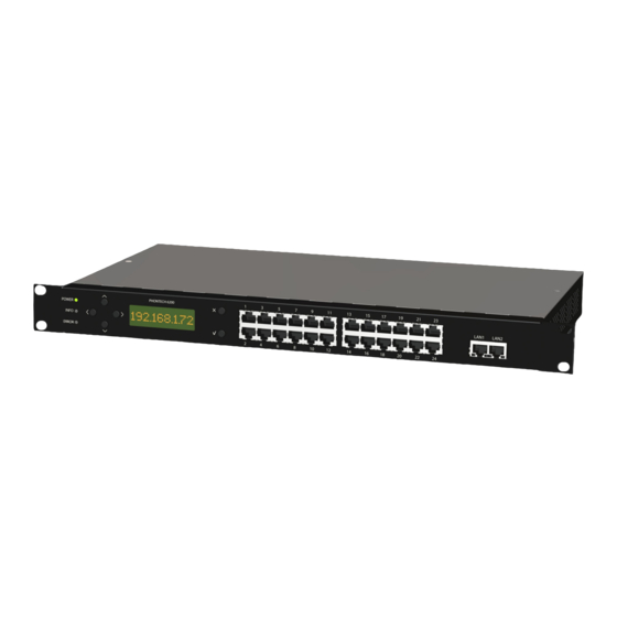
7 NETWORKING EQUIPMENT 7.1 PHONTECH 7200 The Phontech 7200 LAN switch includes 24 Gb Ethernet and 2Gb SFP ports for fiber connectivity. 26 ports in total. The switch is fully manageable through the Web and Command line interface. 24 Ethernet ports 2 SFP Gb ports PoE, 24 ports Dual power supply... - Page 188 7.2 SF-300 24 port Ethernet switch with PoE The SF-300 Ethernet switch with Power over Ethernet is required for the connection of IP telephones. Connect the IP telephones to the SF-300 switch using Cat5e patch panels. The SF-300 is in turn connected to the Phontech 6200’s Ethernet connection.
-
Page 189: Accessories
8 ACCESSORIES 8.1 50 PORT TELEPHONY PATCH PANEL The 50 port Cat3 patch panel can be used when connecting FXS, FXO, UPN and E&M lines to the Phontech 6200 when structured cabling is used in the installation. This drawer style patch panel allows for easy access during termination of the field cable. -
Page 190: 6205 48 Port Patch Panel For Ships Cable
8.3 6205 48 PORT PATCH PANEL FOR SHIPS CABLE. The Phontech 6200 is primarily designed for use with structured cabling. When using traditional ships cable, the 6205 patch panel is used together with the termination module. The patch panel is connected to the termination module using a 25 pin DSUB cable. -
Page 191: Y-Cable For 6205 Patch Panel
8.4 Y-CABLE FOR 6205 PATCH PANEL When using this patch panel in combination with the E&M line board, and the keying inputs or outputs are used, a special Y-patch cable is required, Zenitel item no: 4000018472. The black RJ-45 jack is connected to the E&M port on the Phontech 6200 unit, the red RJ-45 jack is the audio line and the yellow RJ-45 jack is the key IO. -
Page 192: Phontech 6216 Emergency Pa Unit
8.5 PHONTECH 6216 EMERGENCY PA UNIT Key Features • Noise cancelling / Close talk gooseneck microphone • Emergency PA activation button • Protection against unintended use: sliding cover Dimensions: 144 x 96 x 83 mm (LxWxD Microphone height: 360 mm p/n 4000087299 v.I Page 8-190... - Page 193 Zenitel and its subsidiaries assume no responsibility for any errors that may appear in this publication, or for damages arising from the information therein. Phontech products are developed and marketed by Zenitel. The company’s Quality Assurance System is certified to meet the requirements in NS-EN ISO 9001. Zenitel reserves the right to modify designs and alter specifications without notice. ZENITEL PROPRIETARY. This document and its supplementing elements, contain Zenitel or third party information which is proprietary and confidential.
Need help?
Do you have a question about the Phontech ICS 6200 and is the answer not in the manual?
Questions and answers