Table of Contents

Subscribe to Our Youtube Channel
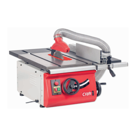
Related Manuals for Axminster Craft AC216TS


Summary of Contents for Axminster Craft AC216TS
- Page 1 Code 104926 Original Instructions AC216TS 216mm Table Saw Code: 104932 Cabinet Stand Code: 104930 Sliding Table Kit for AC216TS Table Saw Code: 104931 Floor Stand for AC216TS Table Saw for AC216TS Table Saw AT&M: 21/03/2019 BOOK REF : 105785...
- Page 2 EN 60204-1:2006+A1+AC Type Table Saw Model AC216TS and conforms to the machinery example for which the EC Type-Examination Certificate No BM 50424431 has been issued by Laizhou Fulin Machinery Co., Ltd. Signed at: Wenchang Road Street Nanwuli Industry Yard Laizhou, Shandong261400 China and complies with the relevant essential health and safety requirements.
-
Page 3: What's Included
What’s Included Quantity Item Part Model Number AC216TS Basic Table Saw Flexible Hose Side Extension Table Hose Clips Rear Extension Table Push Stick Operating Handle Wheel Knobs Blade Locking Bar Rip Fence Assembly 24mm Spanner Rip Fence Extension 13-15mm Spanner... -
Page 4: Optional Accessories
Optional Accessories Code 104931 Floor Stand Assembly Quantity Item Part Leg Brackets Long Upper Support Struts Short Upper Support Struts Long Lower Support Struts Short Lower Support Struts Threaded Rubber Feet Floor Stand Bag of Fixings Code 104932 Cabinet Stand Assembly Quantity Item Part... - Page 5 Optional Accessories Code 104930 Sliding Table Kit Assembly Quantity Item Part Sliding Carriage Support Bracket Cap head Bolts and Washers for Support Brackets Height Adjusting Blocks Hex Key Fence Mitre Casting with Lift & Shift Clamping Handle Tool Post with Washer/Nut for Hold Down Clamp Hold Down Clamp Fence Distance Stop with Micro Adjuster &...
-
Page 6: General Instructions For 230V Machines
Code 104933 Craft Table Insert / Code 104928 Mitre Fence Quantity Item Part Table Insert for the AC216TS Table Saw 19mm Mitre Fence General Instructions for 230V Machines The following will enable you to observe good working • Carry out a final check e.g. check the cutting tool... - Page 7 Specific Instructions for Table Saws Make sure the saw blade is the correct type for the job in hand. After switching off, never try to slow the saw down more Do not force the saw, if the saw begins to ‘stall’ you are ‘forcing quickly by applying side pressure (with a piece of wood?) to the cut’...
-
Page 8: Specification
Specification Code 104926 Model AC216TS Rating Craft Power 1.1 kW Blade Dia/Bore 216mm/30mm Blade Tilt 0° to 45° Max Depth of Cut @ 45˚ 45mm Max Depth of Cut @ 90˚ 65mm Max Width of Cut with Fence 370mm Table Size... - Page 9 Assembly Fig 06-07-08 Fig 12-13 4. Repeat for the rear extension table (C), making sure you line up the machined slots in the table with the 19mm mitre ‘T’ slots in the cast iron table. Secure both extension tables together, Hose mounting plate see fig 09-10-11.
- Page 10 Assembly Fig 17 Clamping knob Insert plate 3-8mm Gap between the riving knife and the blade 7. Raise the saw by first releasing the rise & fall operating 9. Locate the crown guard (K), flexible hose (L) and hose wheel clamping knob, remove the five cross head screws clips (M).
- Page 11 Assembly Fig 35 Fig 38-39-40 11. Put to hand four M8 Bolts with washer/nuts (U) and rip fence rail with scale (G). Insert two bolts with washers up through the holes to the underside end of the side extension ‘T’ Slot table (B) and lightly screw on two bolts.
- Page 12 Assembly 104926 Basic Table Saw Step 4 AC216TS Table Saw assembled for work bench setup Step 5 104931 Optional Floor Stand Locate all the components on page 04 and assemble as follows. Step 1 Step 6 Step 2 Step 7 Step 3 Remove the table saw’s feet, see figs 03-04, remove the two...
- Page 13 Assembly 104932 Optional Cabinet Stand Step 5 Locate all the components for the cabinet stand as shown on page 04-05 and follow the instructions below. Step 1 Step 6 Hinges Step 2 Step 7 Step 3 Line up the holes Step 8 Step 4...
- Page 14 Assembly Fig 45-46-47 104930 Optional Sliding Table Kit 1. Locate the carriage support brackets (20) and cap head Cap head bolt bolts/washers (21). Offer up the elongated slots in the right/left hand brackets with the threaded holes to the side of the saw assembly (A) and secure in place using the cap head bolts/ washers (21), see fig 42-43-44.
- Page 15 Assembly Fig 50-51-52 Fig 54-55-56-57 Table stop pin knob Cap head bolts Pivot bolts 6. Place a level across both tables, using a hex key adjust both 4. Locate the sliding table (28), turn the table over and pull out and twist the table stop pin knob so it’s in the unlocked height adjusting blocks (22) and the two pivot bolts on each position, see fig 50-51.
- Page 16 Assembly Fig 58-59 Fig 62 9. Remove the washer/nut from the tool post (25), insert the post down through the machined holes in both mitre casting (24) and sliding table (28) and secure using the washer/nut, see fig 62. 10. Loosen the hold down clamping knob (26) and slide the assembly down the tool post (25) and clamp in position, see fig 63.
- Page 17 Assembly 90˚ Stop 14. Using a 90˚ square check that the blade is at 90˚ to the fence assembly (29) and make adjustments accordantly, see fig 70. Fig 70 Butterfly knob 12. Slide the fence (29) near the blade but not touching, tighten 104930 Sliding Table the butterfly knobs, see fig 66-67.
-
Page 18: Illustration And Parts Description
Illustration and Parts Description Code 104926 Basic Table Saw Crown guard Flexible hose Riving knife Rear extension table Saw blade Rip fence rail Rip fence clamping handle Saw assembly access panel 45˚ Scale NVR Control panel Rip fence extension Rip fence Cast iron table Hose support bracket 19mm ‘T’... - Page 19 Illustration and Parts Description ON/OFF NVR switch (A), Emergency stop button (B) Optional 104928 Mitre Fence Rise and Fall operating wheel (C) Tilt scale pointer and adjusting screw 100mm Dust extraction moulding Rip fence magnifying glass and index marker Motor and saw assembly Optional 104933 insert gives better material support for cutting thin strips...
- Page 20 Illustration and Parts Description Code 104931 Floor Stand Code 104932 Cabinet Stand Code 104930 Sliding Table...
- Page 21 Illustration and Parts Description Cabinet stand storage door Distance stop (27) with micro adjusting wheel (a) Fence mitre scale, pointer Fence mitre adjusting screw stops for -45˚ to +45˚ and clamping handle Table stop pin knob, engage to Hold down clamp assembly Sliding carriage stop, prevent the table from sliding prevents the sliding table...
-
Page 22: Setup And Adjustment
Set Up and Adjustment The Riving Knife Adjusting the Rip Fence to the Blade 1. Raise the saw blade to its highest point and remove the saw The fence assembly must be parallel to blade crown guard (K) and the table insert, place safely aside, the saw blade for producing accurate cuts. - Page 23 Set Up and Adjustment Adjusting the Pivot Release the locking knob to the centre of the operating wheel (a) to the side of the saw assembly and turn clockwise to pivot the saw to a maximum of 45˚ degrees, indicated on the scale, see fig 82-83-84.
- Page 24 Operating Instructions NOTE: BEFORE USING YOUR SAW, GO ROUND AND MAKE SURE EVERYTHING IS SECURE, FASTENED DOWN, THAT ALL TOOLS ARE CLEARED AWAY FROM THE WORK AREA! NOTE: Secure larger pieces of timber to the table by using the hold down clamp. CHECK: THE BLADE FOR SHARPNESS, MISSING TEETH, RESIN BUILD UP ETC., Cutting Narrow Pieces...
-
Page 25: Changing The Saw Blade
Changing the Saw Blade Fig 95-96-97-98 DISCONNECT THE MACHINE FROM THE MAINS SUPPLY! 1. Raise the saw blade to its highest point, remove the saw blade crown guard, remove the five cross head screws that secure the table insert, place carefully aside and remove the table insert, see fig 91-92. -
Page 26: Maintenance
Maintenance Fig 99-100 1. Keep the saw as clean and free from saw dust build up as is practical. Periodically, remove the saw gullet by removing the side access panel to the side of the machine and undo the two Hex screws on either side of the gullet, see fig 99-100. - Page 27 Exploded Diagrams/Lists Basic Table Saw Diagram A Continues over...
- Page 28 Exploded Diagrams/Lists Basic Table Saw Diagram A Description Front rail Rip fence Adjusting thread rod Right end captor front rail Eccentric wheel Locking knob Left end captor front rail Locking shaft Semi-circle key 3x16 Taping screw ST4.2X10 Locking Knob Angel connection knob Hex.bolt M8X16 Locking spring plate Stop A...
- Page 29 Exploded Diagrams/Lists Sliding Table Kit Diagram B Continues over...
- Page 30 Exploded Diagrams/Lists Sliding Table Kit Diagram B Description Washer 12mm Mounting bracket Circlips for shaft 12mm Mitre guage Stud,hold down Scale mount Disc,hold down Wing nut Spring,hold down Bolt guide Hex.nut M12 Locating bracket Hex. socket cap head bolt M5X12 Locating plate Washer 5mm Scale...
- Page 31 Exploded Diagrams/Lists Cabinet Stand Diagram C Description Washer 8mm Right panel,cabinet stand Hex.nut M8 Left panel, cabinet stand Spring washer 8 Rear panel,cabinet stand Cross recessed pan head screw M6X12 Sidelong support,front panel Access door,cabinet stand Door knob Hex. socket cap head bolt M8X16 Internal shelf Leveling foot Hex.bolt M8X16...
- Page 32 The Axminster guarantee is available on Craft, Trade, Engineer, Air Tools & CNC Technology Series machines Buy with confidence from Axminster! So sure are we of the quality, we cover all parts and labour free of charge for three years! For more information visit axminster.co.uk/3years The packaging is suitable for recycling.
Need help?
Do you have a question about the AC216TS and is the answer not in the manual?
Questions and answers