Table of Contents
Advertisement
Advertisement
Table of Contents

Related Manuals for Yueming CMA1325C-B-A

Summary of Contents for Yueming CMA1325C-B-A
- Page 1 Product Manual Applicable Model: CMA1325C-B-A Version: 1.0...
-
Page 2: Copyright Statement
GD Han’s Yueming Laser Group Co., Ltd. All rights reserved. GD Han’s Yueming Laser Group Co., Ltd. (Han’s Yueming Laser hereafter) reserves the right to modify the products and product specifications described in this manual without advance notice. Han’s Yueming Laser is not responsible to any direct, indirect, or consequential damage or liability caused by improper use of this manual or the product. -
Page 3: Disclaimer And Responsibility Statement
Disclaimer and Responsibility Statement Whole using the machine from our company, users are required to ensure integrity and independence of the product including but not limited to: mechanical, electrical, optical, control software and accessories. Unauthorized modification is strictly prohibited. It is a must to satisfy operating environment and operating specifications specified in the owner’s manual. -
Page 4: Foreword
Foreword Thanks for purchasing the laser engraving machine control system of our company. Before operating, please read this manual carefully to ensure proper operation. Please keep the manual properly for reference. Since the configs are different, certain models do not have the functions listed in this manual. Please refer to the specific functions for details. -
Page 5: Safety Precautions
Safety Precautions Before using the machine, users are required to carefully read this manual and other operating requirements, strictly abide by the operating specifications. Professional are required for operating the machine. Attention The machine uses class 4 laser (strong laser radiation). The laser radiation may possibly cause the following accidents: emblaze the surrounded flammable materials;... -
Page 6: Table Of Contents
Content Copyright Statement ..........................II Disclaimer and Responsibility Statement ....................III Foreword ..............................IV Safety Precautions ............................IV Chapter1. Product Introduction ......................1 Overview ..........................1 Product parameters and requirements ................1 Using environment ........................ 1 Equipment composition ......................2 1.4.1 Auxiliary equipment ...................... - Page 7 3.1.4 Machine level adjustment ....................8 3.1.5 Installing ventilation tube ..................... 9 3.1.6 Installing laser ........................10 3.1.7 Installing water cooling system ................... 11 3.1.8 Installing air pump ......................12 3.1.9 Installing external power ....................13 3.1.10 Equipment grounding ......................13 3.1.11 Installing software and device drivers ................
- Page 8 Light route and optics parts maintenance ................25 Auxiliary equipment maintenance ..................27 4.4.1 Cleaning the fan ........................27 4.4.2 Water chiller maintenance ....................28 4.4.3 Worktable maintenance ..................... 29 Maintenance cycle ......................29 Runtime maintenance ......................30 Maintenance of long-term shutdown ................. 30 Chapter5.
-
Page 9: Chapter1. Product Introduction
CMA1325C-BA non-metal laser cutting machine is a laser cutting machine designed by Guangdong Han's Yueming LaserGroup Co., Ltd. for laser cutting of non-metallic materials. Featuring high-speed, high-precision, high efficiency and cost effective, it is a high-tech product that integrates laser cutting, precision machinery and motion control technology. -
Page 10: Equipment Composition
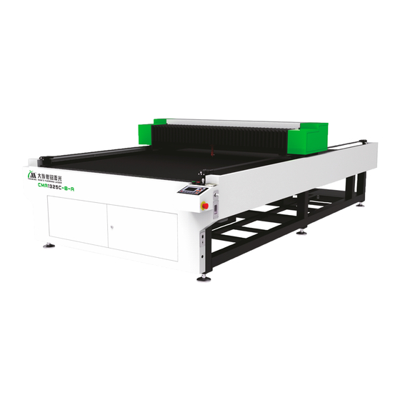
Air pressure: 86-106kpa. 1.4 Equipment composition CMA1325C-B-A laser cutting machine adopts modular design and consists of the frame, beams, cutting head, worktable, console and auxiliary equipment, as shown below: Fig.1-1 CMA1325C-B-A Laser Cutting Machine (refer to real machine) 1.4.1 Auxiliary equipment... -
Page 11: Software Control System
1.5 Software control system SmartCarve4 software is new PC platform software launched by Han's Yueming Laser Group Co., Ltd. and supports process control or data generation. The major functions are computer-aided design, computer intelligent control, graphics and image processing, support for multiple data types, a variety of laser machining processes, multi-layer setting and multi-language support, as described below: Computer-aided design capabilities. -
Page 12: Chapter2. Safety Rules
Chapter2. Safety Rules This chapter mainly introduces safety warnings for protecting personnel and the machine, and makes an introduction to signs used in the owner’s manual. The machine is already equipped with sufficient safety guarantee, yet it is still with certain risk. All the operators are required to carefully read through and well understand the safety rules. -
Page 13: Requirements For Personnel
Block of using emergency stop button (Regular check is required to ensure a good condition for the emergency stop button.) 2.5 Requirements for personnel After trail operation, maintenance personnel from the manufacturer may perform training on the operators. It is the responsibility of machine owner to have operators trained at corresponding level. We have prepared ready a series of training course for your option. -
Page 14: Chapter3. Equipment Installation And Commissioning
Chapter3. Equipment Installation and Commissioning 3.1 Equipment installation 3.1.1 Unpacking steps Before installing, disassemble the wooden box packaging the machine in the following steps: Fig.3-1 Equipment Crate Open the machine body crate with a crowbar (user supplied), and unpack the crate in sequence: top ... -
Page 15: Out Of Box Audit
Fork the machine from the substrate with a forklift and transport to the destination, and unscrew the foot cup. Then open the accessory crate, laser tube crate and laser crate. Accessory Crate Laser Tube Crate 3.1.2 Out of box audit After unpacking, examine the equipment and accessories to ensure that the product has no accident during transport. -
Page 16: Preparation For Installation
Do not unpack the crate without permission. To unpack, first obtain permission from customer service or business personnel of Han's Yueming Laser, or else the company doesn’t assume any responsibility for any accidents. Attention If any problem occurs after unpacking, please inform the customer service or business personnel of Han's Yueming Laser, or directly call Han's Yueming Laser. -
Page 17: Installing Ventilation Tube
Then, place the level meter on the rails of the machine, observe the offset direction of bubble in the level meter; first place the level meter on the rails of the beam; if bubble shifts left, the left side of the machine is higher than the right side;... -
Page 18: Installing Laser
Installation location Installation location Installation Diagram of Exhaust Pipe and Receiver 3.1.6 Installing laser First, move the beam to the rearmost of the machine, and remove the rear shield of the beam; Then, unscrew the screws from the top cover of the support base with a hex wrench; ... -
Page 19: Installing Water Cooling System
Remove this cover before removing the laser tube Adjust the height This label on Fix the wire and tube on of the laser tube the laser tube the laser with insulating with this nut should be tape Laser Installation Diagram Be careful when moving and installing the laser. -
Page 20: Installing Air Pump
Water inlet Water outlet Chiller Fittings Installation Diagram Ensure that the height of the cooling water inside the tank is in predetermined range. To ensure normal circulation of laser cooling water, the water outlet pipe is installed with flow switch. For water-cooled laser tube, the water circulation must be normal, or else it may cause damage to the laser tube. -
Page 21: Installing External Power
Poor grounding will lead to high equipment failure rate, and may lead to other accidents! Han's Yueming Laser does not assume any responsibility and obligation for any resulting faults and accidents. -
Page 22: Installing Software And Device Drivers
Yueming SmartCarve Software System Operating Manual". The user shall take good care of the CD and software dongle. If lost, contact Han's Yueming to purchase. Reinstalling software may lead to loss of system parameters. Please back up the parameters before reinstalling the software or system. -
Page 23: Emergent Stop Button
Main power switch 3.2.2 Emergent stop button This button is mounted on the right side of the mounting plate of the control cabinet. Press any stop button to stopping when the emergency appears. All the dynamic power supply of machine will be switched off after you press the stop button, the machine stay at “stop”... -
Page 24: Motion System Power Button
After get rid of the emergency, reset the stop button by rotating clockwise to relieve stop. Note You should restart the software to restore the machine to work after relieve stop. 3.2.3 Motion system power button The button is on the front cover of the frame. When this button is pressed down, the button indicator lights, and the motion system is powered on;... -
Page 25: Equipment Debugging
3.3 Equipment debugging After installation, equipment commissioning and processing test are required. The equipment commissioning mainly performs condition testing of each module, including motion module, laser module and electrical I/O module. 3.3.1 Switching sequence The main power switch is affixed with description of switching sequence. The switching on sequence: Main power switch ... -
Page 26: Laser Debugging
Limit switch is the hardware sensor equipped on limit position of the two ends of each shaft. After detecting limit triggering signal, the movement shaft will perform emergency stop to avoid “overreaching”. Minimum one limit switch is needed for each shaft to indicate limit position of the current shaft. The installation position of limit switch may differ due to different types of machine, so the triggering signal. - Page 27 3.3.3.2 Light route adjustment Due to vibration during transportation, aberrancy of light route may possibly be caused. At this time, light route correction is needed. Light route of CMA1325C-B-A is as shown in the figure below: Reflector #1 Laser generator Reflector #3 第三反射镜...
- Page 28 Laser irradiates to the center of this hole Reflector Holder Stick a layer of adhesive paper on the inlet of 2# reflector holder, press surrounding of the inlet to make the contour of the inlet appear on the adhesive paper, adjust the screws of 1# reflector holder, and irradiate the laser beam of 1# reflector to the center of 2# reflector;...
-
Page 29: Processing Commissioning
Light inlet Cutting Head Check if the light spots are superposed when the beam is in a different position after adjusting; if not, please re-adjust the optical path in above method until superposed. After adjusting superposition, check if the light spot is in the center of the focusing lens, and if the laser ... - Page 30 First start the equipment in power-up sequence; Then, prepare the materials to be processed, and place the materials on the work surface horizontally; Import or draw graphics to be processed; Set the processing parameters (layer parameters) and related data processing technology (such as path ...
-
Page 31: Chapter4. Care And Maintenance
Chapter4. Care and Maintenance To ensure normal use of CMA1325C-B-Alaser cutting machine, it is necessary to perform routine care and maintenance on equipment. Since the whole machine tool is assembled with high-precision parts, be careful in the routine maintenance process, operate in strict accordance with the rules of each part, and perform maintenance by dedicated personnel to avoid damage to components. -
Page 32: Synchronous Belt And Synchronous Pulley
the axis (guide rail lubricant); push the laser head slowly in lateral direction for several times until the lubricant is evenly distributed on the surface of the linear axis. Clean the guide rail in the same method. According to the frequency of equipment use, periodically (once every 15 days to two months) check if the lubricant of the linear guide rail is sufficient;... -
Page 33: Electrical Inspection
found, timely fastening and maintenance are needed. Meanwhile, the screws of the machine should be tightened one by one with tool after a certain period of use. The first fixation should be performed roughly one month later after using. 4.2 Electrical inspection Mainly check the stability of routine supply voltage, and keep the electrical cabinet of the machine tool clean and well-ventilated. - Page 34 damage or serious pollution, please replace the lenses in time. It is recommended to check and clean the lenses before starting the equipment every day. The polluted lens may cause the following consequences: Effective power of the laser beam is reduced, and power loss is increased; output power is unstable; 2.
-
Page 35: Auxiliary Equipment Maintenance
Unscrew the Remove the jet cup focusing barrel assembly Take out the Unscrew the pressing focusing lens (arrow nut and lens washer indication surface is the convex surface) Fig.5-1 Focusing Lens Removal Procedure Storage of optical lens: Proper storage can maintain intact quality of the optical lens. Storage temperature: 10 ~ 30 °C;... -
Page 36: Water Chiller Maintenance
Remove the screws of the vent cover plate Remove the vent cover plate, and clean the dust or debris from the air intake mesh Then, clean the dust and debris from fan blades Fig.5-2 Cleaning the Fan 4.4.2 Water chiller maintenance The quality and temperature of cooling water directly affect the life of the laser. -
Page 37: Worktable Maintenance
4.4.3 Worktable maintenance CMA1325C-BA uses homemade hollow blade and collection box of Han's Yueming; if the exhaust port is blocked due to too much broken materials in the collection box, the produced dust can’t be discharged promptly and it is easy cause a fire. Please clean the blade and collection box regularly, and clean up the broken materials promptly. -
Page 38: Runtime Maintenance
X-axis rail, Y-axis rail, Z-axis rail and screw seat, ensure the accuracy of the machine tool, keep lubrication of all moving parts and extend the life of X-axis, Y-axis and Z-axis rails; Check the air pipe and water pipe for damage weekly; if damaged, inform Han's Yueming Laser for ②... -
Page 39: Chapter5. Troubleshooting
Chapter5. Troubleshooting Failure Analysis Method Solution The equipment Check if the emergency stop button is pressed down Release the emergency stop button can’t be turned on Main contactor in electrical b ox trips Reset the main contactor Water-cooling system isn’t turned on normally Turn on the water circulation system Water protection is not triggered Check if the chiller is working properly... -
Page 40: Chapter6. Transportation, Shipment And Storage
Chapter6. Transportation, Shipment and Storage 6.1 Packaging CMA1325C-B-AThe chiller, laser and accessories of CMA1325C-G-A laser cutting machine are packed in wooden cases. Other parts are wrapped with PE foam and protective film to protect external objects damaging any part of the laser cutting machine. 6.2 Transport and shipment method and precautions Do not climb or stand on the crate, or place any heavy objects on the crate. -
Page 41: Flat Machine Installation Diagram
6.4 Flat Machine Installation Diagram... -
Page 42: Postscript
Postscript All final right of interpretation of this manual belongs to GD HAN’S YUEMIGN LASER GROUP CO., LTD; we will do our utmost efforts to ensure the accuracy of the contents of this manual. We do not assume any responsibility caused by misspellings and typing errors.
Need help?
Do you have a question about the CMA1325C-B-A and is the answer not in the manual?
Questions and answers