Table of Contents
Advertisement
Quick Links
Download this manual
See also:
User Manual
Advertisement
Table of Contents

Related Manuals for LOYTEC L-VIS


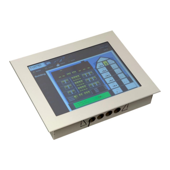
Summary of Contents for LOYTEC L-VIS
- Page 1 L-VIS LOYTEC Visualization User Manual LOYTEC electronics GmbH...
- Page 2 LOYTEC. AST, LC3020, L-Chip, L-Core, L-DALI, L-GATE, L-INX, L-IOB, LIOB Connect, L-IP, L-MBUS, L-OPC, LPA, L-POW, L-ROC, L-STUDIO, L-Switch, L-Term, L-VIS, L-WEB, ORION stack, buildings under control are trademarks of LOYTEC electronics GmbH. ® ®...
-
Page 3: Table Of Contents
2.3.5 Create Menu Structure and Pages ............19 2.3.6 Add Controls to the Page ................. 19 2.3.7 Connect the Data-Points ................20 2.3.8 Write the Project to the L-VIS device ............21 2.3.9 Test the Project ..................21 Quick Start Tutorial BACnet ................22 2.4.1 Add the device to the network .............. - Page 4 LEDs and Buttons ..................... 30 5 Interface Configuration ................32 Selecting the Interface ..................32 Configuring the IP-852 interface ..............33 6 Operating L-VIS ..................34 Touch Screen ..................... 34 6.1.1 Operation ....................34 6.1.2 Calibration ....................35 Data Input ......................36 6.2.1 Simple Schedule Control .................
- Page 5 L-VIS User Manual LOYTEC Controls ......................62 8.5.1 Text Control ..................... 62 8.5.2 Bitmap Control ..................63 8.5.3 Push Button ....................64 8.5.4 Numeric Control ..................64 8.5.5 Bar Control ....................66 8.5.6 Trend Control ................... 69 8.5.7 Date Control ..................... 73 8.5.8 Data Log Control ..................
- Page 6 L-VIS User Manual LOYTEC 9.2.1 Folder List ..................... 111 9.2.2 Data Object List ..................112 9.2.3 Property View ..................113 9.2.4 Buttons ....................113 Object Creation ....................113 9.3.1 User Register ..................113 9.3.2 Local Network Variable (CEA-709) ............. 113 9.3.3 Local Server-Object (BACnet) ..............
- Page 7 L-VIS User Manual LOYTEC 10.4 Configuration Recovery .................. 134 10.4.1 Change Device Configuration ..............134 10.4.2 Change Network Configuration ............. 135 10.4.3 Recover from a failed Update ..............135 11 Special Functions (CEA-709)..............138 11.1 Binding Management ..................138 11.2 XIF Export .......................
- Page 8 L-VIS User Manual LOYTEC 13.4.2 Remote Data Access (FTP) ..............154 13.4.3 Default OPC Access ................154 13.5 Mail Account ....................154 13.6 Info ........................155 14 Advanced Topics..................156 14.1 Access Control....................156 14.2 Undo / Redo ..................... 157 14.3...
- Page 9 L-VIS User Manual LOYTEC 16.1.2 Icon Menus .................... 182 16.1.3 Taskbar Menu ..................183 16.1.4 Bitmap Menu ..................183 16.2 Light Control ....................184 16.3 Animated Bitmaps ................... 185 16.4 Sunblind Demo ....................185 16.5 Split Demo ......................186 16.6 Counter Demo....................
-
Page 10: Introduction
LOYTEC 1 Introduction 1.1 What is L-VIS? L-VIS is a highly flexible and easy to configure device to display and control data in BACnet and CEA-709 networks. The L-VIS configuration software can be run as a ® standalone program as well as an LNS... - Page 11 A real time keeper object, which outputs the current system time. 8 L-VIS functional blocks which can be used to place static or dynamic NVs related to the data points used in the project. Network scanning to find other device on the network and help in creating the required network variables on L-VIS.
-
Page 12: Scope
Network scanning to find other devices and their objects in the network and use them on the L-VIS device without the need to manually enter device and object instance numbers. Supports COV subscription and polling of remote server objects with automatic selection of the best method (COV if available). -
Page 13: Getting Started
2.1 Installing the L-VIS Configuration Application To install the L-VIS Configuration software, execute the setup program and follow the instruction of the installation wizard. The setup program adds an entry for the L-VIS ® Configuration software to the start menu. - Page 14 L-VIS User Manual LOYTEC ® If your device is integrated into the network using an LNS based tool (your device is ® managed by LNS ) and you need to add or remove static network variables from your project or otherwise change the static interface of the device, you must use this connection method to download your project, since the configuration software needs to do several ®...
- Page 15 2.2.1.3 CEA-709 (FT-10 / CEA-852) Connections In this mode, the communication channel is CEA-709 via a LOYTEC NIC such as a NIC- USB, NIC-PCI or NIC-852. The device must first be commissioned (assigned a network address), either by using the same network management tool as used for the other nodes in the network or by entering a suitable unused address in the CEA-709 setup menu.
-
Page 16: Bacnet Devices
2.3.1.1 CEA-709 with LNS: Create the L-VIS device in the LNS database Add the L-VIS device to your LNS network project. Since the L-VIS configuration plug-in already creates the device templates, the device configuration can be read from the device Version 4.2... -
Page 17: Create Dynamic Nvs (Lns Only)
Make sure to set the poll attribute to CLEAR when you create the output variable, otherwise you will not be able to send out any values through this NV. Also, the poll attribute of the input NV should be SET, so that L-VIS is able to fetch an initial value when it boots up. -
Page 18: Create Static Nvs (If No Dynamic Nvs Available)
The main window will show an empty L-VIS project. The list of dynamic network variables available on the device is automatically read in and a list of corresponding data points to access the NVs is generated. -
Page 19: Create Menu Structure And
L-VIS User Manual LOYTEC 2.3.5 Create Menu Structure and Pages The next step is to design a simple test page for this tutorial and use the two data points. The empty project shows the root menu with no entries (menu items). You may change the... -
Page 20: Connect The Data-Points
L-VIS User Manual LOYTEC Container color on the Color property page. Then grab the control at the lower right corner of the container area. NOTE: The position and size you set on the Common Properties page also refers to the value area of the control, not to the selection frame around it. -
Page 21: Write The Project To The L-Vis Device
2.3.8 Write the Project to the L-VIS device We are now ready to write the project to the L-VIS device, but first the project should be saved in a file on the PC. Although it is possible to read the project back from the device, it... -
Page 22: Quick Start Tutorial Bacnet
Reboot the device for the changes to take effect. 2.4.2 Start the L-VIS Configuration Software Run the installed L-VIS configuration software from the start menu of your desktop. Connect to the device by pressing the Connect button from the tool bar, or select the menu item Connect to the Device…... -
Page 23: Create Data Points
BACnet Network Scan and select the item Scan BACnet Network…. Discover the devices on the network, select the L-VIS device, and scan it for objects. Close the scan dialog and use the two server objects found by the scanner to create corresponding client mappings. -
Page 24: Add Controls To The Page
L-VIS User Manual LOYTEC 12x16-ROM-Fixed-R font, so you get a larger item which is easier to select on the touch screen. The menu item object is described in detail in section 8.3. Repeat the steps above to add another menu item and call it „Setup‟. Again, change the Text of the item to read something like „Setup‟... -
Page 25: Write The Project To The L-Vis Device
2.4.7 Write the Project to the L-VIS device We are now ready to write the project to the L-VIS device, but first the project should be saved in a file on the PC. Although it is possible to read the project back from the device, it... -
Page 26: Test The Project
L-VIS User Manual LOYTEC Once the project file is written to the device, the L-VIS reboots and shows the tutorial project on the display. 2.4.8 Test the Project You should now be able to use the device to set the state and the value of the two server objects and immediately see the results on the client mapping input points, since they refer to the local server objects. -
Page 27: Mechanical Installation
3.1 Dimensions and Mounting For information about unit installation, please refer to the installation sheet that came with your unit. This document is also available for download from the LOYTEC website. 3.2 Theft Protection To protect devices of type LVIS-3E100 and LVIS-ME200, they can be fixed to the wall mount frame with the supplied chain as shown in Figure 1. -
Page 28: Electrical Installation
4.1 Connection diagram For information about unit installation, please refer to the installation sheet that came with your unit. This document is also available for download from the LOYTEC website. 4.2 Electrical Characteristics LVIS-3E100/ME200 The electrical characteristics of the LVIS-3E100 and LVIS-ME200 devices are shown in Table 1. -
Page 29: Touch Panel Cleaning Instructions
L-VIS User Manual LOYTEC Characteristics Value Operating voltage 24 VDC ± 10%, or with 90-265 VAC Power consumption 12 inch: 14W, 15 inch: 17W, idle: 3.5W In-rush current Up to 3.7A @ 24 VAC, max. 40ms Operating temperature (ambient) 10°C to +40°C Storage temperature -10°C to +50°C... -
Page 30: Leds And Buttons
Up to four external temperature sensors can be connected to the terminal labeled TEMP. Compatible temperature sensors are available from LOYTEC under the part number L-TEMP1. The temperature range of this electronic sensor specified as -55 to +125°C and the accuracy is +/-0.5°Celsius within the range from -10 to +85°C. - Page 31 L-VIS User Manual LOYTEC Status button Pressing the Status button sends out a service pin message on the IP- 852 or the FT-10/LPT-10 channel (CEA-709 models) or send out an „I Am‟ message (BACnet models). To reset the device to factory defaults, hold the service pin button pressed while the unit boots and release the button within a few seconds when all interface LEDs light up orange.
-
Page 32: Interface Configuration
L-VIS User Manual LOYTEC 5 Interface Configuration 5.1 Selecting the Interface Both the CEA-709 units and the BACnet units have two network interfaces and two different types of communication going on, which should be clearly distinguished: Communications with the configuration software, to read and write configuration data, upgrade the firmware, and retrieve diagnostic data from the device (configuration). -
Page 33: Configuring The Ip-852 Interface
Table 5: Available interfaces 5.2 Configuring the IP-852 interface Before the L-VIS device can be used on an IP-852 channel, the following things have to be configured in the setup menu of the device (see also section 6.3): CEA-709 Settings: If not controlled by the IP jumper, select the IP852 interface mode on the CEA-709 settings page. -
Page 34: Operating L-Vis
L-VIS devices use a resistive touch screen. This type of screen can only detect one touch position at a time, that is, you cannot press two buttons at once. The screen delivers raw data which must be converted to LCD pixel positions before it can be used;... -
Page 35: Calibration
L-VIS User Manual LOYTEC The simple and intuitive touch operation is used to select menus, select controls and enter data on the input keypad. This is straight forward. A short touch on a control will also trigger touch, release, short press, and selection actions connected to it. -
Page 36: Data Input
6.2 Data Input As shown in the tutorial, L-VIS uses configurable control elements to display and input data. Whether a control is selectable for data input depends on the data points connected to it as well as on the current access level of the user: ... -
Page 37: Simple Schedule Control
L-VIS User Manual LOYTEC Push button mode: For text controls and bitmap controls, a push button mode can be activated. This mode assigns a new value to a control whenever the control is selected. The next value is determined by selecting the next or previous entry in the mapping table, so the user may cycle through the available values. - Page 38 L-VIS User Manual LOYTEC before all of the operations are available. For more information on access control setup for schedule controls refer to section 8.5.9. NOTE: The update mode used by schedule controls is fixed to Focus Loss, meaning that the new schedule configuration will be written to the scheduler only at the time the control leaves edit mode.
- Page 39 L-VIS User Manual LOYTEC 6.2.1.7 Edit Values of a Preset To change the physical values assigned to a value preset, touch the preset name to open the dropdown box. From the box, select the command edit to open a small window showing the current values of the preset.
-
Page 40: Extended Schedule Control
L-VIS User Manual LOYTEC 6.2.1.12 Edit Exception Days To change the days on which a certain exception schedule is active, select the exception day in the left column and touch the headline of the time table to open a dropdown menu. - Page 41 L-VIS User Manual LOYTEC following information: The time at which the preset becomes active, the time until this preset stays active, and the name of the scheduled preset. Event List: This page shows a list of all events applicable to a selected day. Note that this list does not exactly represent the presets that will be in effect on that day.
- Page 42 L-VIS User Manual LOYTEC 6.2.2.3 Event List This page displays a list of all events which are applicable to the selected day. Note that an event which is generally applicable to a certain day may not yield to a new value being scheduled, since the event may partially or fully overlap with other, higher priority events.
- Page 43 L-VIS User Manual LOYTEC Name: A custom name for this event. If supported by the underlying scheduler unit, a name can be entered here. Note that even if this field is available, a length limit for the name may apply.
-
Page 44: Setup Menu
L-VIS User Manual LOYTEC the user to enter a new name via the keyboard. To close the template editor, press the close button in the top right corner of the window. 6.2.2.7 Calendar Pattern Editor If an event references a global calendar pattern and the calendar allows the user to edit the pattern definition, an edit button will be shown next to the dropdown list from which a calendar pattern is selected. - Page 45 Storage: This page is available on devices which support external data storage like USB and SD card memory. The buttons on this page can be used to save and restore device backups, L-Vis project files, and to write current trend log data to the external memory.
-
Page 46: Custom Setup Menu
L-VIS User Manual LOYTEC The CEA-709 models provide the following additional pages: CEA-709: On this page, the device can be given a CEA-709 address (domain/subnet/node) and can be set online. This is useful to connect to the device in standalone mode, before the device is actually commissioned in a network, for example because the project needs to be downloaded first to define the static interface of the device and there is no TCP/IP connectivity available. -
Page 47: Configuration Software
Context menus are an important part of the workflow, since most operations related to the objects of the L-VIS project are accessible from the context menu of the object in question. The context menu is usually opened using a right mouse button click on the desired object in the tree view, but for objects visible in the LCD preview, the same context menu may also be opened by a right mouse button click on the preview of the desired object. -
Page 48: Add Objects
L-VIS User Manual LOYTEC 7.2.1 Add Objects Most context menus contain a number of Add… commands to add new objects to the selected object. Only those objects which may be added to the selected object are listed in the context menu. -
Page 49: Xml Export / Import
L-VIS User Manual LOYTEC 7.2.3.4 Template References If the copied object contains instances of templates and the object is pasted into another project, the configuration software will try to identify a suitable template in the destination project based on the number, type, and order of objects in the template. Template instances, for which there is no suitable template available, will cause the original template from the source project to be copied over to the destination project automatically. - Page 50 L-VIS User Manual LOYTEC possible. For example the duplicate operation, when run with this naming rule, will create a data source Test1 from the original source Test. Search and Replace: This setting is used to specify a simple search and replace algorithm.
-
Page 51: Expand / Fold Tree
L-VIS User Manual LOYTEC In contrast to the ‘duplicate and reassign’ operation, this operation only attempts to NOTE: reassign the data points to other existing and compatible data sources. New sources will not be created on the fly. Instead, the reassign operation fails if no compatible data source can be found using the new name. -
Page 52: Main Menus
L-VIS User Manual LOYTEC A hidden object will not be visible on the device after project download, but it can be made visible during run time via a trigger command. 7.3 Main Menus Many of the items in the main windows menus do not require additional explanation, as they are commonly found in modern PC software. -
Page 53: Common Property
L-VIS User Manual LOYTEC Go back once more to the menu objects of your project and open the Menu/Page property page. For each menu, set the Container Width such that the longest item text fits the menu. If your items use graphical icons as well, you may need to adjust the width reserved to the left of the item text such that the widest icon will fit. -
Page 54: Common Properties
L-VIS User Manual LOYTEC NOTE: The object name specified here has nothing to do with the appearance of the object on the device, if it is a visible object at all. The name on this page is just the name of the object in the object hierarchy. - Page 55 L-VIS User Manual LOYTEC Object Type Usage of the Text field Menu Directly used for the menu title. Menu Item Directly used for the menu item text. Format string which may contain one %s placeholder, which will be replaced by a string taken from a mapping table or a connected string data point.
-
Page 56: Color
L-VIS User Manual LOYTEC removed, and existing ones can be replaced by others or resized as necessary. Graphics import is discussed in detail in section 14.12. Depending on the object type, the image is used according to the following table: Bitmap is used for…... - Page 57 L-VIS User Manual LOYTEC NOTE: Most colors are named such that it is clear to which element of an object the color applies, like Text, Background, Selection and similar. Depending on the selected object, the naming of the colors will change accordingly. How the available colors are used by a particular object can be found in the objects documentation.
-
Page 58: Object Description
8 Object Description 8.1 Introduction Every L-VIS project is built using a number of different objects. Each of the objects has a relatively simple function. To build a complex project, the simple objects are put together and organized in an object tree, which is shown in the tree view of the configuration software. -
Page 59: Menu
L-VIS User Manual LOYTEC 8.2 Menu A menu object is used to manage a collection of menu item objects. On the device, a menu is a window which opens on the left side of the display and shows the items which are contained in the menu. -
Page 60: Menu Item Properties
L-VIS User Manual LOYTEC Each item object can hold zero or more page objects and zero or one menu object, as shown in the object hierarchy diagram. It depends on the connected objects, what will happen when the user selects the menu item. -
Page 61: Page Properties
L-VIS User Manual LOYTEC 8.4 Page Page objects are simple objects to organize the control elements which are visible on the device. When a page object is connected to a menu item and the item is selected from the menu, the page and all the controls on it will be shown on the display. Previously visible controls will be hidden, but will continue to exist on the device (so that a trend control may continue to record data, for example). -
Page 62: Controls
L-VIS User Manual LOYTEC 8.5 Controls All objects which can be displayed on a page are called controls. This is because they are usually used to provide to user with an interface to control a data point value or trigger actions. -
Page 63: Bitmap Control
L-VIS User Manual LOYTEC <html>: If the contents start with an <html> tag, they will be parsed as HTML source and displayed in the browser. Useful if a complete HTML page was created in a web design tool and pasted into the text control. -
Page 64: Push Button
L-VIS User Manual LOYTEC NOTE: For best results, use PNG format for your images and embed transparency information as alpha channel in the image. Using this image in true color projects, transparency will be fully automatic based on the alpha channel data. When used in VGA color projects, the... - Page 65 L-VIS User Manual LOYTEC string for your control, if you don‟t want to enter it yourself on the common properties page. In the area Input Mode, the properties concerning value input are defined: Value Range: The values entered in these two fields (min –max) define the limits for input of new values.
-
Page 66: Bar Control
L-VIS User Manual LOYTEC Left Justified: This option causes padding characters to be inserted to the right of the converted number, so that the number appears left justified within the specified field width. The option has no effect if the field width is equal to or smaller than the space occupied by the converted value. - Page 67 L-VIS User Manual LOYTEC Position and size of a bar control, as defined on the common properties page, correspond to the frame of the bar control, as described above. It does not correspond to the selection frame drawn around the whole bar control.
- Page 68 L-VIS User Manual LOYTEC The Flags control which components are drawn and how they are drawn. The following flags are available: Horizontal Bar: The bar control is turned by 90 degrees and the bar moves from left to right (lower values left) instead of up and down.
-
Page 69: Trend Control
L-VIS User Manual LOYTEC NOTE: The static sunblind image in the background may be replaced by a bitmap control with a mapping table to show the current rotation of the sunblind. Example 3: A combined display of a current value and a set point can be created by using two bar controls. - Page 70 L-VIS User Manual LOYTEC Color Name Element to which the color applies Labels Numbers of the value scale and the time scale. Horizontal Grid Horizontal grid lines (if the grid is enabled). Vertical Grid Vertical primary grid lines (if the grid is enabled).
- Page 71 L-VIS User Manual LOYTEC the next higher shift interval which results in an integral shift of the graph (in pixels). The Flags to enable or disable the tick marks and the scale are the same as for the value axis.
- Page 72 L-VIS User Manual LOYTEC NOTE: Use the preserve data option with care and avoid unnecessary saving of unimportant data, since these operations may take up a significant amount of system resources and adversely affect performance and life time of the device in case they are over-used in a project.
-
Page 73: Date Control
L-VIS User Manual LOYTEC encoding, according to the FTP protocol extension RFC2640. Clients who support this extension can then display these file names correctly. Most web-browser based FTP clients either detect the UTF-8 encoding automatically or provide an option where the user may set the desired encoding. -
Page 74: Data Log Control
L-VIS User Manual LOYTEC There are two different display modes for a date control: a text based mode and a graphical analog clock simulation. Even though one date control can only use one of the two modes at a time, two or more date controls may be used together to display the time as an analog clock and the date as text on the same page. -
Page 75: Schedule Control
In this case, the title line will allow the user to select the schedule which he wants to view or edit. Please see section 6.2.1 for details about operating a schedule control in standard mode on the running L-VIS device. Version 4.2 LOYTEC electronics GmbH... - Page 76 In this mode, it is therefore possible to use the smallest built-in font to save space on the screen and enable the user to see as much information as possible, especially on the smaller L-Vis devices. 8.5.9.4 Schedule Control Properties The properties to set on the Schedule Control property page define the basic appearance of the control and control access to various operations which modify configuration data.
- Page 77 L-VIS User Manual LOYTEC DIN-1355 date format: This option selects the German DIN-1355 specification to display dates. In this format, the order is day, month, and year, separated by decimal points (DD.MM.YYYY). US date format: This option selects the US date format, which uses the order month, day, and year, separated by slashes (MM/DD/YYYY).
- Page 78 L-VIS User Manual LOYTEC minute as a suffix. Used for some languages to yield commonly used time representations, for example Japanese: 5 時 24 分 Use event colors for value: This option changes the way the event colors are used to draw the weekly overview.
- Page 79 L-VIS User Manual LOYTEC Color Name Element to which the color applies Text Color for all text areas of the control. Highlight Highlight color of 3D frames. Shadow Shadow color of 3D frames. Horizontal Grid Grid line color. Scroll bar and scroll arrow graphics, only available when the control is Scrollbar used in standard UI mode.
-
Page 80: Alarm-List Control
L-VIS User Manual LOYTEC different values are used and frequently changed, for example when a temperature set-point or other discrete value is scheduled. The color selection in this mode will cause all values scheduled at standard priority to be drawn in event color 1, with colors 2 and 3 only used for values scheduled at the same day at higher priorities. - Page 81 L-VIS User Manual LOYTEC the same control, in which case the control will display a list of all alarms from all connected points in chronological order. The control always displays the newest alarm at the top with older alarms following further down.
- Page 82 L-VIS User Manual LOYTEC Use am/pm as prefix: Available when 12 hour mode is enabled, tells the control to use the strings for AM and PM as a prefix instead of a suffix. This option is required for some languages to yield correct 12 hour time representation.
-
Page 83: Vector Drawing Control
L-VIS User Manual LOYTEC Color Name Element to which the color applies Text Color for the text printed by the control. Highlight Highlight color of 3D frames. Shadow Shadow color of 3D frames. Horizontal Grid Grid line color. Button graphics and page information in the navigation bar and text color Buttons for the label of the ACK button. - Page 84 L-VIS User Manual LOYTEC Line Width: Defines the line with used to draw the lines of a line or polygon drawing and the outline of a rectangle or circle. Corner Radius: Available for rectangles, defines the desired corner radius for a rounded rectangle.
-
Page 85: Data Point
L-VIS User Manual LOYTEC and the first point of the drawing and the lines will be drawn according to the new shape. To add more points, repeat the procedure as needed. Press the right mouse button to end point insertion mode. - Page 86 ISO-10646 character set and are transferred in UTF-8 encoded format. This way, it is possible to exchange strings in any language between two L-VIS devices. The data point object is the object created when Add Data Point… is selected from the context menu of a control to assign a data point to it.
-
Page 87: Data Point Properties
L-VIS User Manual LOYTEC It is important to understand this concept to understand what can be configured on the Data Point property page. The key is that there can and usually will be multiple data points referencing the same data object. - Page 88 L-VIS User Manual LOYTEC Value Changes Only: This option causes the data point to forward updates only if the value actually changed. It is very useful to avoid unnecessary operations caused by repeated updates with the same value, provided that the data point does not represent an event, in which case all updates must be processed and this option should not be used.
-
Page 89: Mapping Table
L-VIS User Manual LOYTEC are received. Since the value which will be saved is the value of the referenced data object, this option will also affect all other data points which reference the same data object. NOTE: The persistent option is useful for output data points which need to be sent out after system boot (System Startup flag is set) but are controlled by actions or math objects instead of direct user input. -
Page 90: Action Objects
L-VIS User Manual LOYTEC possible numeric value. The valid range for each entry in the mapping table is defined to reach from the value of the entry itself, up to but not including the value of the succeeding entry. If this is the last entry, it is used for all values up to +infinite, since there is no more entry to define an upper bound. -
Page 91: Action Properties
L-VIS User Manual LOYTEC In any case, the action objects need a parent object which is able to feed the required information to the connected action, such that the action may monitor what‟s going on and trigger at the right moment. Currently these objects are controls and data point connectors. - Page 92 L-VIS User Manual LOYTEC Service Pin Message: Execute the system command „send service pin message‟, which is supported by CEA-709 models. Lock Pages (Logout): Immediately protects all locked pages. The user has to enter the PIN code again to unlock the locked pages.
- Page 93 L-VIS User Manual LOYTEC release: The action is triggered when the touch screen is released while inside the control, or when the touch position moves outside the control while the screen is still being touched. short press: The action is triggered when the control is released after it was touched for a period shorter than the configured long press threshold.
- Page 94 L-VIS User Manual LOYTEC NOTE: To avoid confusing situations, it is required that only one object at a time is processing user input. Therefore, if an action is connected to a control and the action uses a trigger mode which depends on user input, for example touch, release, or selection, the user input will no longer be processed by the control but will instead be forwarded to the action.
-
Page 95: Collections
L-VIS User Manual LOYTEC NOTE: The delay value (waiting xxx ms after each time) always applies. The action trigger will always be locked for the given duration after each time the action fired, preventing the same action to fire again until the wait time expired. This can be used to limit the frequency at which an action may fire. -
Page 96: Collection Handling
The alarm generator object is used to monitor input data points and issue alarms based on rules which are set on the Alarm Generator property page. For a discussion of alarming on L-VIS devices in conjunction with the underlying network technology and system wide alarms, please also refer to section 9.5 of this manual. -
Page 97: Alarm Generator Properties
Boolean value may be translated into any two values, one to signal „alarm clear‟ and one for „alarm set‟. This is most useful if the generated alarm is to be processed further or displayed on the L-VIS device, for example to trigger actions or display warning messages. -
Page 98: Application Hints
L-VIS User Manual LOYTEC Define the Alarm Condition using the radio buttons at the bottom left of the page. The available choices allow basic monitoring functionality and always define the condition, under which the alarm should be SET. If the value no longer satisfies the condition, the alarm will be cleared. -
Page 99: Data Point Connectors
L-VIS User Manual LOYTEC Like on the SET data point, keep the Alarm Condition at Above Max, but enter T2 as the maximum, instead of T1. For the Action, select Clear on Alarm Leave and select the desired output value from the dropdown list at the right. This time, the Value for Alarm Clear box will be active, while the others will be grayed out. -
Page 100: Mathematic Objects
L-VIS User Manual LOYTEC A data point connector has no visible representation on the display and is therefore not related to any of the visible objects. It can only be connected to a collection object, as described earlier. To create a new data point connector, use the context menu of the collection object to which you want to add the data point connector. -
Page 101: Application Hints
L-VIS User Manual LOYTEC may find it more convenient to construct the formula using the list at the right, instead of the input at the bottom. To learn more about postfix notation, there are a lot of resources and articles readily available on the internet. -
Page 102: Function List
L-VIS User Manual LOYTEC NOTE: Especially for projects which use a lot of cascaded formulas, where the result of one formula is used as input to a number of other formulas, it may cause a big difference in CPU usage whether results of the same value are forwarded to other math objects in the... -
Page 103: Trigger Objects
L-VIS User Manual LOYTEC Function Return Value v1)) / 2 Returns the hyperbolic cosine of v1, which is defined mathematically as (exp(v1) + cosh(v1) exp(-v1)) / 2 Returns the hyperbolic tangent of v1, which is defined mathematically as sinh(v1) /... - Page 104 L-VIS User Manual LOYTEC Add Data Record: Instructs the control to record the current data of the data record to which the trigger is connected. See also section 8.5.8 for more info about data log controls and data records.
-
Page 105: Templates
L-VIS User Manual LOYTEC versa. Subsequent updates which lead to the same result do not repeatedly fire the trigger, as opposed to the above modes. Updates resulting in a CHANGE to TRUE: This mode fires the trigger only when an update is received which results in a TRUE trigger condition and the condition was previously FALSE. -
Page 106: Creating A Template
L-VIS User Manual LOYTEC 8.14.2 Creating a Template To add a new template, use the Add Template command from the context menu of a template folder. A new template object will be created and a fresh page will be shown in the LCD preview. -
Page 107: Instantiating A Template
L-VIS User Manual LOYTEC 8.14.3 Instantiating a Template There are a few different methods to create actual instances of one or more templates on a page of the project: In the tree view, drag the template object and drop it on the page on which a new instance of this template is desired. -
Page 108: Local Changes
L-VIS User Manual LOYTEC template. Although this is not strictly required and thus not enforced by the software, it is in most cases the only meaningful configuration. Consider the following example: The data point setup contains a set of data point folders, one for each room (room1, room2, room3, and so on). - Page 109 L-VIS User Manual LOYTEC In order to keep the adjustments even when the template itself is changed, they are stored together with the template instance object. If a stored change is no longer applicable, for example because the object to which it applies was removed from the template, the change is discarded.
-
Page 110: Data Point Management
Every data object on L-VIS has a distinct direction of data flow, either read (input) or write (output). This is important because the data flow direction determines how a data point will be used by other objects in the tree. -
Page 111: User Interface
BACnet devices, since it maps the value of the existing data object on the L-VIS device to a data point on a different device. Depending on the direction of data flow, the mapping can be either read (poll or COV) or write. -
Page 112: Data Object List
ID by which this object may be referenced. Also shown is the number of times this object is currently referenced from the main object tree (the L-VIS project). Only data objects which are currently unused (the Use column shows 0) may be removed from the list. -
Page 113: Property View
9.3.2 Local Network Variable (CEA-709) For CEA-709 models, local network objects refer to local network variables on the L-VIS device. If there are dynamic NVs present on the device, suitable data objects will be created automatically. -
Page 114: Local Server-Object (Bacnet)
BACnet defines the direction of data flow from the point of view of the application running on the L-VIS device. An analog input object therefore accepts input from the user and transmits this data out to other devices on the network. An analog output object receives data from the network and outputs it to the application (show data on the display). -
Page 115: Remote Network Object
Once opened, the contents of the file will be parsed and suitable data object templates will be created in the file import folder. These templates are then used in a later step to create client mappings for use on the L-VIS device (see section 9.3.4.3 below). 9.3.4.2 Network Scan Scanning an existing network is another way to generate template points. - Page 116 L-VIS device running the scan. To start the scan, use the context menu of the scan folder and select Scan LNS Database.
-
Page 117: Local Scheduler And Calendar
(for a network variable input on a remote device, you will see an input data object in the import folder). Once the point is used to create a remote network object on the L-VIS device, the direction will change, since a network variable output will be required to send data to the remote devices network variable input. -
Page 118: Scheduler Point Configuration
L-VIS User Manual LOYTEC 9.4.3 Scheduler Point Configuration To configure the local scheduler points, select the command Configure Schedule from the context menu of the scheduler point. The same dialog which appears when a new scheduler is created is shown and allows one to configure the scheduler. Of course, this step can also be done directly when the point is created. -
Page 119: System Resources
L-VIS User Manual LOYTEC It is always in effect when the project is downloaded and it will have an influence on the static interface of a CEA-709 device. The other part is the dates entered in calendar patterns and the actual schedule of each scheduler (when the scheduler should output which value preset as well as the definition of the value presets themselves). - Page 120 L-VIS User Manual LOYTEC definitions from all calendar entries. A date definition is for example a single date, a date range, or a week and day pattern (every last Friday in April). Number of local schedulers: This is the number of local scheduler objects which should be available on the device.
-
Page 121: Resource Allocation
L-VIS User Manual LOYTEC NOTE: It is possible to enter anything here, until the project is actually saved or downloaded. At this point in time, the software will check that the resources configured here are sufficient to support the projects configuration. If this is not the case, this dialog will automatically open so that the settings may be adjusted. -
Page 122: Algorithmic Reporting
CEA-709 devices do currently not support the mechanism of intrinsic reporting. Instead, the application needs to provide an algorithm which determines if an alarm state is reached. On L-VIS devices, the alarm generator objects as described in section 8.10 are used for this purpose. - Page 123 L-VIS User Manual LOYTEC From the points in the import folder, select the scheduler points you are interested in and use the command Use on Device to create suitable remote scheduler points in your project. Note that any existing calendar is automatically imported as well.
-
Page 124: Alarm Clients
L-VIS User Manual LOYTEC On BACnet devices, the new data points can be used right away to exchange configuration data with the scheduler on the remote device. Just connect the new scheduler data point to a schedule control to view and edit the configuration of the remote devices scheduler. -
Page 125: Common E-Mail Properties
If nothing is configured here, the mail may still be sent using an action object in the L-VIS project (please refer to section 8.8 for a description of action objects). To send the mail based on the value or state of a data point, follow these steps: Version 4.2... -
Page 126: Attachments
L-VIS User Manual LOYTEC Add the desired data point using the Add… button. Valid data points to use for mail triggers are normal analog, binary, and multistate values as well as alarm server and client points. Depending on the type of data point, select the conditions which should trigger this mail. -
Page 127: Standard Procedures (Cea-709)
The followings steps will be required to integrate a new device. Create a new device in your database using the provided device template for the L-VIS device you are using (FT-10 or IP-10L). Create all dynamic network variables on the device which are required for your project. - Page 128 The procedure when run as a plug-in is fairly automatic: Create a new device in your database using the provided device template for the L-VIS device you are using (FT-10 or IP-10L). Commission the device, so that the configuration software can communicate with ...
-
Page 129: Pre-Programmed Device
In some cases, it may be necessary to integrate an already programmed device into a network. This can only be done with static NV projects, since dynamic NVs are stored in the network database and not the L-VIS project and are therefore not transportable from one network to another. -
Page 130: Device Replacement
NOTE: The following procedures assume that the L-VIS project file is available to the PC which runs the configuration software. If this is not the case, the project must first be uploaded from the old device and saved to a file. -
Page 131: Mixed Projects (Static And Dynamic)
Create a new database or network project in your network management tool, adding the PCs network interface and a new L-VIS device and connect them using a suitable channel. Connect the new device physically to the network interface of your PC, or otherwise make sure that the PC can communicate with the device in the new network project. -
Page 132: Configuration Change
L-VIS User Manual LOYTEC dynamic NVs created and then the project needs to be loaded again, so that the dynamic NVs which were not available the first time can be used. The recommended procedure is a combination of the above two procedures. -
Page 133: Static Nv Change
L-VIS User Manual LOYTEC Execute all required changes to the dynamic NV interface using your network management software. This includes adding new NVs and removing old NVs as required. Once the required changes were made, start the configuration software or, if it is already running, use the Update Data Points button from the tool bar to read the new set of available dynamic NVs from the device. -
Page 134: Configuration Recovery
L-VIS User Manual LOYTEC static interface of the already integrated device and take over the existing bindings. The recommended procedure is as follows: Run the configuration software in standalone mode and connect to the device, preferably using a TCP/IP connection. -
Page 135: Change Network Configuration
Instead, check the following things upfront, before starting the download: Run the configuration software standalone, without connection to any L-VIS device and load the project which is considered to match the current device in the network. - Page 136 L-VIS User Manual LOYTEC 10.4.3.1 Failure before Database Update If the procedure failed before the database update, that is, the device template in the database is still the old version, the device must be rolled back to the last project as well, so that the database and the device match again.
- Page 137 L-VIS User Manual LOYTEC NOTE: Reverting back to the last working setup is much easier if a backup of the database is available. In this case, first restore the database from the backup and then simply follow the appropriate procedure for device replacement, using the last working project file. In this case, the configuration software may also be used in plug-in mode during the replace procedure, since the recover functions are not required.
-
Page 138: Special Functions (Cea-709)
L-VIS User Manual LOYTEC 11 Special Functions (CEA-709) 11.1 Binding Management When the configuration software is run in plug-in mode, additional functions to export, import, and remove the network bindings of the device are available from the Tools menu. The Export Bindings… function scans the database and outputs all current bindings into a text file in CSV format. -
Page 139: Offline
The CEA-709 models normally support the CEA-709.1-B standard, which means that the device accepts the extended network management commands used to configure the extra resources available on such devices (for example up to 512 address table entries on L-VIS). However, since the standard requires devices which were once configured using extended network management commands to no longer accept any of the older commands. - Page 140 L-VIS User Manual LOYTEC Figure 3: Create a function block Drag an input or output network variable shape from the LonMaker® network management tool shape sheet and drop it on the function block. The dialog in Figure 4 is shown.
- Page 141 L-VIS User Manual LOYTEC Figure 5: Create network variable dialog In the dialog (Figure 6), select the network variable on the node to which the new dynamic network variable will be connected afterwards. The dynamic network variable will get some attributes of the selected variable, like the SNVT type, assigned. Click on OK to confirm your choice.
-
Page 142: Nl220
This completes the creation of the new dynamic network variable (Figure 8). The dynamic network variable can now be bound to other network variables like a normal network variable and can also be used as a data point source or data point sink in the L-VIS configuration software. -
Page 143: Alex
(Figure 10). Figure 10: Network variable connection window 11.4.3 Alex To create dynamic network variables in Alex, add the L-VIS device to your project. Select Virtuelle Funktionseinheiten and click on Neue Virtuelle Funktionseinheit (Figure 11). Version 4.2 LOYTEC electronics GmbH... - Page 144 L-VIS User Manual LOYTEC Figure 11: Alex main window Enter a name in the dialog (Figure 12) and press OK. Figure 12: Virtuelle Funktionseinheit dialog Open the Netzwerkvariablen collection in the tree view and select Neue Netzwerkvariable (Figure 13). Version 4.2...
- Page 145 L-VIS User Manual LOYTEC Figure 13: Create new network variable In the Netzwerk Variable dialog (Figure 14), select the device template (Gerätevorlage) and the network variable to which the new dynamic network variable will be connected. Figure 14: New network variable dialog The dynamic network variable will get attributes like the SNVT type from this network variable.
-
Page 146: Built-In Lonmark
Figure 15: Finished creation of new network variable ® 11.5 Built-in L Objects The CEA-709 models of L-VIS provide a number of static function blocks which are available for use, even when no project is loaded. These blocks are described in the following sections. 11.5.1 Timer Object ®... -
Page 147: Relay / Lcd Backlight Control
LCD backlight. To overrule the value which is adjusted in the L-VIS Plugin Software, the state part of the nviSwitch network variable has to be set to 1. In that case, the value part of the network variable controls the brightness of the display from 0 to 100%. -
Page 148: Hvac Temperature Sensor
The configuration properties are described in detail in the L Functional Profile specification. On the L-VIS device, the temperature sensor object reads the current temperature value from an external temperature sensor connected to the input terminals labeled 'TEMP' on the device. -
Page 149: Special Functions (Bacnet)
(object name and description, as well as state texts). Since all strings in an L-VIS project are Unicode strings (ISO-10646), the default setting is to use UCS-2 encoded strings for BACnet properties. However, especially in the US... -
Page 150: Project Settings
L-VIS User Manual LOYTEC 13 Project Settings Using the command Project Settings from the File menu, a number of advanced options can be controlled which apply to the entire project. The dialog is organized in a number of property pages, which are explained below. -
Page 151: Sound
L-VIS User Manual LOYTEC Hide menu after: The amount of idle time after which an open navigation menu is closed automatically, without changing to a different page. Hide selection after: The amount of idle time after which the selection frame of the last used control is removed. -
Page 152: System Settings
L-VIS User Manual LOYTEC Hide setup menu: This option instructs the device not to add a link to the built- in setup menu, so that the built-in setup is not accessible. The user may provide customized setup pages instead, matching the local language and the design of the other pages. -
Page 153: Display
13.3.2 Display Properties For L-VIS devices, which have fixed display hardware, this area shows the properties of the display for the selected device model. Devices which can support configurable resolution and/or color depth allow the user to change these settings here. -
Page 154: Remote Data Access (Ftp)
(one byte per pixel). If the VNC client supports this mode (color map mode), the VNC server on the L-VIS device will tell the client that this is the preferred display mode to optimize speed and bandwidth usage. However, many clients only support true color modes, where either two or more bytes per pixel need to be transferred or the color resolution will be reduced. -
Page 155: Info
L-VIS User Manual LOYTEC If the SMTP server requires authentication, set the option Enable user authentication and enter a user name and password. Other types of authentication, such as SSL/TLS or POP- before-SMTP are currently not available and are usually only required by free mail service providers, which have no other way of authenticating their users. -
Page 156: Advanced Topics
(for example using an RFID card). The access controller can communicate the successful authentication over the network to the L-VIS device, where a suitable access level can be set directly, without using a PIN code. -
Page 157: Undo / Redo
L-VIS User Manual LOYTEC 14.2 Undo / Redo The current version of the configuration software provides a simple form of undo and redo. To make use of this feature, it is required to take a snapshot of the project from time to time by pressing the Snapshot button in the tool bar, using the Snapshot command from the Edit menu, or the keyboard shortcut (Ctrl+A). -
Page 158: Find Similar Objects
L-VIS User Manual LOYTEC NOTE: This function may cause the rightmost or bottommost control to move by a few pixels, if the original distance between first and last control did not allow the other controls to be evenly distributed between them. This may be the case because a control can only be placed at an integer pixel position, which means that the calculated space between the controls can either be 4 or 5 pixels, but not 4.5 pixels. -
Page 159: Local Data Point Capacity
Settings dialog, which is accessible from the File menu of the main window. The default setting, which matches the configuration of an empty L-VIS device, is 512 and must not be changed if the static interface of the device should stay at default configuration. If the static interface is allowed to change, the capacity may be increased to support up to 1000 NVs using the input field Max. -
Page 160: Avoiding Update Loops
This may cause the actuator to send out an update on the feedback output, which will be received by L-VIS on the input SI, which in turn will be copied by the data point connector to the output SO and so on. The result can have adverse effects on the network performance and the performance of the devices in the loop, so special care should be taken to avoid such setups. -
Page 161: Font File Location
L-VIS project file, if the project is to be edited on a different PC, where the font may not be available at the same location. -
Page 162: Pcf File Format
(e.g. True Type fonts) to PCF format. These fonts can then be used on the L-VIS device. Tools which are freely available to convert from Windows TTF fonts to PCF format include otf2bdf to convert the TTF or OTF font to BDF format of a given pixel size and bdftopcf to convert the BDF file into a PCF font. -
Page 163: Using Color Bitmaps
Such a tool could for example browse a network or a database, pick out some devices which should be visualized in an L-VIS project, select suitable templates from an XML template database, create the required data point configuration to allow communication with the desired devices and complete the templates by linking the data point references to the automatically created data points. -
Page 164: Using Sounds
14.13 Using Sounds The 12 inch and 15 inch L-Vis devices as well as recent versions of the LWEB-800 OPC client software support the playback of sounds and streaming of MP3 data (web radio). To start and stop sound playback, new actions were introduced. -
Page 165: Format Strings
The format string used in text controls and numeric controls is equivalent to the format strings used by the ANSI-C printf function. L-VIS will always use the given format string to format exactly one argument, which will be a string, an integer, or a double precision floating point number, depending on the type of control and its configuration. - Page 166 14.14.1.4 Length Modifier The conversion specifier may normally be preceded by a length modifier, defining the physical size of the arguments data type. In the L-VIS implementation, this modifier is not necessary and may be omitted in all cases. 14.14.1.5 Conversion Specifier This is the character that specifies the type of conversion to be applied.
-
Page 167: Date Format Strings
A „%‟ is written. No argument is converted in the process. 14.14.2 Date format strings The format string used by L-VIS date controls is equivalent to the format string used by the ANSI-C function strftime. The locale setting on the L-VIS device for the purpose of formatting dates is fixed to U.S. - Page 168 L-VIS User Manual LOYTEC The hour (24-hour clock) as a decimal number (range 0 to 23); single digits are preceded by a blank. (See also %H.) The hour (12-hour clock) as a decimal number (range 1 to 12); single digits are preceded by a blank.
-
Page 169: Regular Expressions
L-VIS User Manual LOYTEC The date and time in date(1) format. %% A literal „%‟ character. Some conversion specifiers can be modified by preceding them by the E or O modifier to indicate that an alternative format should be used. If the alternative format or specification does not exist for the current locale, the behavior will be as if the unmodified conversion specification were used. - Page 170 L-VIS User Manual LOYTEC The symbol \b matches the empty string at the edge of a word, and \B matches the empty string provided it's not at the edge of a word. A regular expression may be followed by one of several repetition operators: The preceding item is optional and matched at most once.
-
Page 171: Appendix A: Examples
With this example, we will be able to show the state of a SNVT_switch (e.g. a lamp) and control the state from the L-VIS device, using a text control. Text controls are typically used to display a complex text or to allow input where the user can select between several different input strings (e.g. -
Page 172: Bitmap Control
L-VIS User Manual LOYTEC For the nvoSwitch.state network variable, set the NV Update Flags value to Focus Loss. The configuration now looks similar to Figure 16. The project can now be loaded into the L-VIS device. To change the state of the output network variable, select the text control by operating the jog dial until a frame is displayed around the text control. -
Page 173: Numeric Control
L-VIS User Manual LOYTEC For the nvoSwitch.state network variable, set the NV Update Flags value to Focus Loss. Select the mapping item in the tree view and go to the Mapping tab. In the value list, select OFF. Click on Select Bitmap and choose a bitmap which should be displayed when the switch is OFF. -
Page 174: Example 2: Using Data Point Conversion And Hiding Of
The example will show how to use the hide flag in order to load the project into the L-VIS device with the localized configuration. The example walk- through description assumes that a dynamic network variable nviTemp of type SNVT_temp_p is already created on the L-VIS device. -
Page 175: Example 3: Freeze Warning, Alarms And Registers
Celsius, set the Invisible Page flag on the Menu/Page tab of the corresponding page. Load the project into the L-VIS device. Only the page, which does not have the Invisible Page flag set, shows up in the L-VIS device (see Figure 19). - Page 176 L-VIS User Manual LOYTEC values up to 0,1°C, the FREEZE text will be shown. Values between 0,1°C and 2,99°C will show ATTENTION, where as values starting with 3°C will show NORMAL in the text control. Figure 20 shows a screenshot of the mapping table.
-
Page 177: Example 4: Using Text Mapping And Date Control
On the Mapping tab of the data point, select the AL_ALM_CONDITION. Click on Select Bitmap and choose a bitmap which is displayed when the alarm condition is met. Load the project into the L-VIS device. Figure 22: Freeze alarm with text and bitmap controls 15.4 Example 4: Using text mapping and Date Control... - Page 178 Go to the mapping tabs of the other text controls and load the stored mapping table. Load the project to the L-VIS device. To show the correct text the update interval of the timer object has to be set to 1 second.
- Page 179 L-VIS User Manual LOYTEC Figure 24: Text Watch project Version 4.2 LOYTEC electronics GmbH...
-
Page 180: Appendix B: Solutions
16 Appendix B: Solutions This section describes solutions for some standard applications. The solution projects can be found in the Projects directory of the L-VIS configuration software install directory. 16.1 Implementing Menus By default, the user can navigate in a project using the main menu, submenus and push and drag operations. - Page 181 L-VIS User Manual LOYTEC Figure 26: Active page bitmap Figure 27: Inactive page bitmap The bitmaps are aligned to form a row of tabs. On each tab, a text control is placed with identifies the page and the page links (in the example it is called Page 1, Page 2,…). To each of the inactive page bitmap controls an action object is assigned.
-
Page 182: Icon Menus
L-VIS User Manual LOYTEC Figure 29: Flat tabs and menu button 16.1.2 Icon Menus Another common implementation to navigate in menu trees is to use icon menus as shown in the icon menu example (see Figure 30). Figure 30: Icon menu On an empty page as set of bitmap controls is placed. -
Page 183: Taskbar Menu
L-VIS User Manual LOYTEC Using the icon menus, it is also possible to implement the whole navigation without the default menu. In that case, the main menu page should have the checked the default page checkbox in the Menu/Page tab. -
Page 184: Light Control
L-VIS User Manual LOYTEC Figure 32: Bitmap menu configuration 16.2 Light Control The project “Solution_examples_manual.lcp” contains a “Switch Demo” page. Figure 33: Switch demo page The example uses a bitmap control in push button mode to switch the state of a SNVT_switch on or off. -
Page 185: Animated Bitmaps
L-VIS User Manual LOYTEC assigned to the bitmap controls. The increase and decrease operations are executed by two mathematic objects. The operation results are exchanged between the mathematic object and the bitmap controls using a register. 16.3 Animated Bitmaps The project “Solution_examples_manual.lcp” contains an “Animation Demo” page. -
Page 186: Split Demo
L-VIS User Manual LOYTEC Figure 35: Sunblind demo configuration Like in the switch example, the sunblind demo uses bitmap controls together with action objects to move a sunblind to special positions or move the sunblind up, down or stop the sunblind. -
Page 187: Counter Demo
L-VIS User Manual LOYTEC Figure 36: Split example configuration The split demo shows how to merge the input of a SNVT_state variable into a single bitmap control. In some projects it is required to evaluate the input of a SNVT_state variable, where only one bit is set, and display the result in a single bitmap or text control. - Page 188 L-VIS User Manual LOYTEC Figure 37: Counter demo configuration The counter demo shows how to use a bar graph control to simulate the fill level of a container. An empty container is formed by a bitmap control. On top of the bitmap control, a bar graph control is placed.
-
Page 189: Revision History
Author Description 2004-11-03 Initial revision V1.1 2004-06-04 New screenshots, added configuration chapter, fixes 2006-01-24 Changes for L-VIS 3E100 2006-04-04 1.5.1 Added documentation for color mapping, theft protection. Updates after review. 2006-10-13 2.0.0 Rewrote a large part of the manual to make it more useful (hopefully) based on user feedback.
Need help?
Do you have a question about the L-VIS and is the answer not in the manual?
Questions and answers