Table of Contents
Advertisement
Quick Links
Advertisement
Table of Contents
Troubleshooting

Related Manuals for LOYTEC L-DALI


Summary of Contents for LOYTEC L-DALI
- Page 1 L-DALI DALI Light Controller User Manual LOYTEC electronics GmbH...
- Page 2 Version 5.2 Document 88077110 LOYTEC MAKES AN D YOU RECEIVE N O WARRAN TIES OR CON DITION S, EXPRESS, IMPLIED, STATUTORY OR IN AN Y COMMUN ICATION WITH YOU, AN D LOYTEC SPECIFICALLY DISCLAIMS AN Y IMPLIED WARRAN TY OF MERCH AN TABILITY OR FITN ESS FOR A PARTICULAR PURPOSE.
-
Page 3: Table Of Contents
1 Introduction ....................15 Overview ......................15 L-DALI Models ....................19 Scope ........................19 2 What’s New in L-DALI ................20 New in L-DALI 5.2 .................... 20 New in L-DALI 3.2 .................... 23 3 Quick-Start Guide ..................25 Hardware Installation ..................25 3.1.1 Models without built-in DALI Bus Power Supply ........ - Page 4 L-DALI User’s Manual LOYTEC Enclosure ......................45 4.1.1 LDALI-3E10X and LDALI-ME204 ............45 4.1.2 LDALI-E101-U, LDALI-3101-U and LDALI-E101-U ......45 Product Label ....................46 Mounting ......................46 LED signals ....................... 47 4.4.1 LDALI-3E10X and LDALI-ME204 ............47 4.4.2 LDALI-E101-U, LDALI-3101-U and LDALI-E101-U ......49 4.4.3 Wink Action ....................
- Page 5 L-DALI User’s Manual LOYTEC 5.2.13 BACnet Recipients (LDALI-20X only) ........... 68 5.2.14 BACnet Time Master (LDALI-20X only) ..........68 5.2.15 BACnet Restart Notifications (LDALI-20X only) ........69 5.2.16 BACnet ACL (Access Control List, LDALI-20X only) ......69 5.2.17 Backup and Restore ................. 70 5.2.18 Debug .......................
- Page 6 L-DALI User’s Manual LOYTEC Data Points ...................... 110 6.1.1 Overview ....................110 6.1.2 Timing Parameters ................. 111 6.1.3 Default Values ..................111 6.1.4 Persistency ..................... 111 6.1.5 Parameters ..................... 112 6.1.6 Behavior on Value Changes ..............112 6.1.7 Custom Scaling ..................113 6.1.8 Protected Data Points ................
- Page 7 Installation ....................... 139 7.1.1 Software Installation ................139 7.1.2 Registration as a Plug-In ................ 139 7.1.3 Operating Modes ..................141 Workflows for the L-DALI ................141 7.2.1 Involved Configuration Files ..............142 7.2.2 On-Line ....................142 7.2.3 Off-Line ....................143 7.2.4 Replace an L-DALI ................
- Page 8 L-DALI User’s Manual LOYTEC 7.7.3 Data Point List ..................172 7.7.4 Property View ..................173 7.7.5 Tracking Data Point Usage ..............175 7.7.6 Managing Multistate Maps ..............176 7.7.7 Organizing Favorites ................177 7.7.8 Managing Property Relations ..............178 7.7.9 CEA-709 Properties ................178 7.7.10 BACnet Properties .................
- Page 9 L-DALI User’s Manual LOYTEC 7.10.4 Limit E-mail Send Rate ................206 7.11 Local Schedule and Calendar ................. 207 7.11.1 Create Calendar Patterns ................ 207 7.11.2 Create a Local Scheduler ............... 207 7.11.3 Configure Scheduled Data Points ............208 7.11.4 Configure Scheduled Events ..............209 7.11.5 Configure Exception Days ..............
- Page 10 L-DALI User’s Manual LOYTEC 8.1.3 Alarm Log CSV File ................235 8.1.4 Emergency Light Test Log CSV File ............ 235 CEA-709 Interface (LDALI-10X only) ............235 8.2.1 Node Object #0000 ................236 8.2.2 Real-Time Keeper Object #3300 ............236 8.2.3 Calendar Object #0006 ................236 8.2.4 Scheduler Object #0007 ................
- Page 11 L-DALI User’s Manual LOYTEC Redundant Ethernet (LDALI-E101-U/LDALI-E201-U only) ..... 368 9.3.1 Ethernet Cabling Options ............... 368 9.3.2 Upstream Options .................. 369 9.3.3 Preconditions ..................370 9.3.4 Switch Settings ..................370 9.3.5 Testing ....................371 9.3.6 Example switch configuration ..............372 10 Firmware Update ..................
- Page 12 L-DALI User’s Manual LOYTEC 15 Revision History ..................393 Version 5.2 LOYTEC electronics GmbH...
- Page 13 DNS ........Domain Name Server, RFC 1034 DST ........Daylight Saving Time GMT........Greenwich Mean Time IP ......... Internet Protocol LSD Tool ......LOYTEC System Diagnostics Tool IP-852........Logical IP-Channel, for tunneling CEA-709 packets according to CEA-852 LAN ........Local Area Network LSD Tool ......
- Page 14 L-DALI User Manual LOYTEC RTT ........Round-Trip Time RTU ........Remote Terminal Unit SL ........Send List SMTP ......... Simple Mail Transfer Protocol SNTP ........Simple Network Time Protocol SNVT ......... Standard Network Variable Type SSH ........Secure Shell SSL ........Secure Socket Layer TLS ........
-
Page 15: Introduction
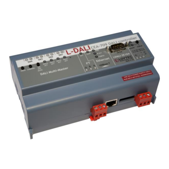
Figure 1: L-DALI supports up to four DALI channels. The L-DALI lineup features 1, 2, or 4 independent DALI channels. Up to 64 DALI-based luminaries per DALI channel can be controlled individually or via 16 groups. All luminaries are monitored for lamp defect. - Page 16 DALI network the L-DALI controller represents a DALI master controller. On the CEA-709 or BACnet network the L-DALI controller offers a NV interface or a BACnet server objects respectively to control the ballasts and the sensors connected for the DALI network.
- Page 17 Some lighting controller applications do not need a connection to the CEA-709 or BACnet network. Therefore the L-DALI controller can control a DALI network as a standalone device with the aid of the supported automation functions (alarming, scheduling, and trending).
- Page 18 L-DALI User Manual LOYTEC DIN rail mountable /CEA-709 models only: Fully compliant with CEA-709, CEA-852, and EN 14908 standard Supports L TP/FT-10 or CEA-852 Ethernet (IP-852) channels (selectable) Control of DALI capable ballasts via NVs ...
-
Page 19: L-Dali Models
Loop objects providing constant light controller functionality 1.2 L-DALI Models This Section provides an overview of the different L-DALI models in Table 1. This table identifies the different features of the L-DALI models. Models that possess a certain feature have a check mark () in the respective column. If a feature is not available in the particular model, the column is left blank. -
Page 20: What's New In L-Dali
Custom user registers and BACnet objects can be created and data points belonging to the static L-DALI application interface can be OPC exposed. Further, the BACnet network can be scanned and client maps can be created from local BACnet objects to remote BACnet objects. - Page 21 L-DALI User Manual LOYTEC DALI Scene Configuration A new page was added to the L-DALI Web-UI allowing configuration of DALI scenes (see Section 5.3.5). Scene configuration also supports colour scenes with colour temperature and changeable light colour. DALI Installation Wizards A DALI search wizard was added to the DALI installation Web-UI to quickly locate and assign DALI devices.
- Page 22 Storing Project Documentation directly on the Device A new page on the L-DALI Web-UI allows uploading project documentation and setting-up links to external documentation files (see Section 5.2.20). Storing documentation directly on the device ensures its availability (e.g. for a service technician) later on.
-
Page 23: New In L-Dali 3.2
L-DALI User Manual LOYTEC 2.2 New in L-DALI 3.2 This section describes the major changes and new features. For a full list of changes refer to the Readme file. New Constant Light Controller Modes The constant light controller application offers some new Modes: ... - Page 24 Support for the ThebenHTS PlanoSpot 360 DALI multi-sensor was added. Change the DALI Short Address If required the DALI short address, which was assigned to a DALI device by the L-DALI, can be changed via the Web-UI (see Section 5.3.4.9).
-
Page 25: Quick-Start Guide
LDALI-PWR4-U or LDALI-PWR2-U power supply together with the L-DALI. Connect the L-DALI to the LDALI-PWR4-U and to the DALI network as shown in Figure 5. To allow for easy configuration it is recommended to always connect the L-DALI to the Ethernet network. -
Page 26: Models With Built-In Dali Bus Power Supply
3.1.2 Models with built-in DALI Bus Power Supply Connect the L-DALI to the power and to the DALI network as shown in Figure 5. To allow for easy configuration it is recommended to always connect the L-DALI to the Ethernet network (if available). - Page 27 Press down the jog dial. Then turn it one step to the right. The manual override must change to “On”. Now all DALI ballasts should be switched on and the status LED on the L-DALI should light up green. Turning the dial one more step right the manual override must change to “Off”.
-
Page 28: Device Configuration
L-DALI User Manual LOYTEC Now all DALI ballasts should be switched off and the status LED on the L-DALI should light up orange. Turn the dial one step right once more. This should not change the state of the DALI ballasts but return the manual override back to the auto-mode (control via CEA-709/BACnet interface). -
Page 29: Ip Configuration Via The Web Interface
As an alternative to the console interface the Web interface can be used to configure the device. In a Web browser enter the default IP address 192.168.1.254 of the L-DALI. Note that if your PC has an IP address in a subnet other than 192.168.1.xxx please open a command tool and enter the following route command to add a route to the L-DALI. - Page 30 L-DALI User Manual LOYTEC Figure 9: Example Start Screen. Click on Config in the left menu. You will be asked to enter the administrator password in order to change the IP settings. Enter ‘loytec4u’ and select Login. Figure 10: Enter ‘loytec4u’ as the default administrator password.
-
Page 31: Ip Configuration Via The Lcd Display
L-DALI User Manual LOYTEC Figure 11: Enter IP address and gateway. 3.3.3 IP Configuration via the LCD Display Device models with an LCD display can also be configured to their basic settings through jog dial navigation on the LCD UI. Turn the jog dial to navigate between menu items and press to enter a menu or go into selection mode. -
Page 32: Connect To Device In Stand-Alone Mode
Install the LINX Configurator software from the setup.exe. This file can be downloaded from www.loytec.com. This tool can be used as a stand-alone tool or as LNS plug-in. In this example we will use the LINX Configurator software as a stand-alone tool. -
Page 33: Scan Dali Channel
Select the DALI channel and click on the Scan Channel button shown in Figure 15. Figure 15: LINX Configurator software, scan DALI Channel. The L-DALI device scans the selected channel and displays all detected devices as shown in Figure 16. In case an error occurs see Section 11.4 for a description of the error codes and possible reasons. -
Page 34: On Mark
L-DALI User Manual LOYTEC 3.4.3 Assign Lamps, Sensor and Button to L /BACnet Objects To identity which of the four detected DALI ballasts is which physical lamp, select one and click the Wink button. The corresponding lamp blinks for the configured wink duration. -
Page 35: Grouping Lamps
L-DALI User Manual LOYTEC 3.4.4 Grouping Lamps Lamps which are assigned to a group can be controlled together by the corresponding group object. We will create three groups: One for the lamps near the window, one for the lamps near the corridor and one for all lamps in the room. -
Page 36: Parameterize The Dali Button
T2 for “Off/Down”, both controlling group “room_306”. This will allow us to control all lights in the room together. 3.4.7 Download Configuration To download the configuration into the L-DALI device click on the Download Configuration button in the toolbar. Version 5.2... -
Page 37: Calibrate Light Sensor
Figure 25: LINX Configurator software, After Configuration Download. 3.4.8 Calibrate Light Sensor The L-DALI device allows calibrating the light sensor under up to seven different light conditions to counter any non-linearity of the sensor. However, in many cases it is enough Version 5.2... -
Page 38: Configuration Using Web Interface
Figure 27: Calibrate Light Sensor. 3.5 Configuration using Web Interface As an alternative to the LINX Configurator PC Software the Web interface of the L-DALI can be used. In a Web browser enter the IP address as set up in Section 3.3. -
Page 39: Scan Dali Channel
A detailed description of the L-DALI Web interface can be found in Chapter 5. 3.5.1 Scan DALI Channel In the L-DALI Web interface click on Commission in the left menu. If not already logged in you will be asked to enter the administrator password. Enter ‘loytec4u’ and select Login. -
Page 40: On Mark
L-DALI User Manual LOYTEC The L-DALI scans the DALI channel and lists the detected devices under Scanned Devices not in Database in the lower halve of the Web interface (see Figure 29). In case an error occurs see Section 11.4 for a description of the error codes and possible reasons. -
Page 41: Calibrate Light Sensor
Entering – in the field will relinquish an active override. 3.5.4 Calibrate Light Sensor The L-DALI device allows calibrating the light sensor under up to seven different light conditions to counter any non-linearity of the sensor. However, in many cases it is enough to calibrate the sensor with a single light condition which is near the setpoint. -
Page 42: Parameterize The Dali Button
L-DALI User Manual LOYTEC If possible dim artificial light in room until luxmeter show desired lux setpoint. To dim the light select the rooms DALI group in the Dim lights drop down box, enter a desired dim value in the field Level and press the Set button. -
Page 43: Configuration Of Bacnet Interface (Ldali-20X Only)
3.6 Configuration of BACnet Interface (LDALI-20X only) 3.6.1 Configure BACnet Interface To allow integrating the L-DALI to a BACnet network a network wide unique device ID and device name must be configured. This is best done using the web interface: Version 5.2... - Page 44 L-DALI User Manual LOYTEC Similar to the configuration of the IP address connect to the L-DALI using your Internet browser. Click on Config and then BACnet Config in the left menu. Figure 36: BACnet Device Configuration. Enter a unique device ID and device name as shown in Figure 36.
-
Page 45: Hardware Installation
L-DALI User Manual LOYTEC 4 Hardware Installation 4.1 Enclosure 4.1.1 LDALI-3E10X and LDALI-ME204 The LDALI-3E10X and LDALI-ME204 enclosure is 159 mm wide for DIN rail mounting, following DIN 43 880 (see Figure 37). Figure 37: LDALI-3E10X and LDALI-ME204 Enclosure (dimensions in mm [inch]). -
Page 46: Product Label
The device comes prepared for mounting on DIN rails following DIN EN 50 022. The device can be mounted in any position. However, an installation place with proper airflow must be selected to ensure that the temperature of the L-DALI device does not exceed the specified range (see Chapter 13). -
Page 47: Led Signals
The L-DALI power LED lights up green when power is supplied to terminals 24, 25, and 4.4.1.2 Status LED The L-DALI is equipped with a red status LED (see Figure 37). This LED is normally off. During boot-up the status LED is used to signal error conditions (red). If the fall-back image is executed the status LED flashes red once every second. - Page 48 Please add the device to a CEA-852 IP channel (register in configuration server). Flashing green or orange at 1 Hz: The L-DALI’s CEA-709 side of the gateway has not been commissioned yet. The color indicates the CEA-852 IP channel status as described above.
-
Page 49: Ldali-E101-U, Ldali-3101-U And Ldali-E101-U
Manual override to on Table 5: Status LED patterns. 4.4.3 Wink Action If the L-DALI receives a wink command on any of its network ports, it shows a blink pattern on the CEA-709 or CNIP activity LEDs and the DALI activity LEDs (LDALI-3E10X and LDALI-ME204) or ... -
Page 50: Dali Mode Button
L-DALI without LCD display are equipped with a DALI Program button (“PROG”, see Figure 37). It is used to replace a broken ballast. When the button is pressed, the L-DALI scans the selected DALI channel for missing and unconfigured ballasts. If exactly one missing ballast and one unconfigured ballast are found on a channel, the unconfigured ballast is used to replace the missing ballast. - Page 51 L-DALI User Manual LOYTEC Below are menu items. Turn the jog dial to navigate between menu items and press to enter a menu or go into selection mode. When in selection mode turn the jog dial to alter the value and press again to quit the selection.
-
Page 52: Dip Switch Settings
Table 6: DIP Switch Settings for L-DALI. 4.8 Terminal Layout and Power Supply The L-DALI provides screw terminals to connect to the network as well as to the power supply. The screw terminals can be used for wires of a maximum thickness of 1.5 /AWG12. -
Page 53: Ldali-3E10X
The LDALI-3E10X models do not provide the DALI bus power supply for any of the connected DALI channels. Thus, on each DALI channel a proper external DALI bus power supply must be provided. For this purpose LOYTEC recommends the use of LOYTEC’s DALI bus power supply LDALI-PWR4-U or LDALI-PWR2-U, which is capable of providing the DALI bus power for the four or two DALI interfaces respectively. -
Page 54: Ldali-E101-U And Ldali-E201-U
DALI channel! 4.9 Wiring Connect the L-DALI to the DALI network as shown in Figure 5 and Figure 6. For easy configuration, it is recommended to always connect the L-DALI to the Ethernet network (if available). -
Page 55: Ldali-3E10X And Ldali-3101-U
Important: When using shielded network cables, only one side of the cable should be connected to earth ground. Thus, the shield must be connected to earth ground either at the L-DALI terminals or somewhere else in the network. Version 5.2... -
Page 56: Web Interface
5.1 Device Information and Account Management In a Web browser enter the default IP address 192.168.1.254 of the L-DALI. Note that if your PC has an IP address in a subnet other than 192.168.1.xxx you must open a command... - Page 57 L-DALI User Manual LOYTEC Figure 43: Device Information Page The device information page shows some general information about the device in the General Info section. This includes the product model and the current firmware version. Below, it shows important operational parameters, such as free memory, CPU load, system temperature and supply voltage, time synchronization status and system uptime.
-
Page 58: Device Configuration
(2) operator is able to read more sensible information such as calendar data. (3) admin has full access to the L-DALI and can make changes to its configuration. Note that the user accounts are also used to log on to the FTP and Telnet server. -
Page 59: Port Configuration
L-DALI User Manual LOYTEC An empty port number field sets the default port number. An empty time value field disables the time setting. 5.2.1 Port Configuration This menu allows configuring the device’s communications ports. For each communication port, which is available on the device and shown on the label (Port 1, CEA-709, Ethernet), a corresponding configuration tab is provided by the Web UI. -
Page 60: Ip Host Configuration
Figure 48: FTP server configuration on the Ethernet port. 5.2.3 IP Host Configuration The L-DALI models, which provide more than one IP interface possess a separate IP Host tab for editing all common host settings. These settings affect all IP interfaces on the entire device. -
Page 61: Device Configuration (Ldali-10X Only)
L-DALI User Manual LOYTEC If the device possesses more than one IP interface the Default Gateway setting defines the gateway of a given IP interface, which is going to route all non-local network traffic. One of the existing IP interfaces with a separate network must be selected here. - Page 62 This is optional and for informational purposes only. If the CEA-852 device on the L-DALI is used behind a NAT router, the public IP address of the NAT router or firewall must be known. To automatically detect the NAT address leave the Auto-NAT checkmark enabled.
-
Page 63: Global Connections Configuration
L-DALI User Manual LOYTEC 5.2.5 Global Connections Configuration The CEA-852 device used for global connections (see Section 6.3.4) can be configured on the Ethernet port. The global connections function is always enabled on the CEA-852 device. This is indicated by the checkbox Global Connections (CEA-852) on the Ethernet tab of the port configuration page as shown in Figure 51. -
Page 64: Vnc Configuration
30000ms / 3 retries. 5.2.7 VNC Configuration LOYTEC devices equipped with an LCD display also provide remote access over Ethernet to the LCD display. The VNC protocol is used for this purpose and the device implements a VNC server for exposing the display. The VNC server is by default disabled on the device. -
Page 65: Ms/Tp Configuration (Ldali-Me204 Only)
Typically, the SMTP server port can be left at 25. In the field Source e-mail address, enter the e-mail address of the L-DALI’s e-mail account. In the field Source e-mail sender name enter a name that the e-mail will display as the source name. Note, that only ASCII characters are allowed in the name. -
Page 66: System Configuration
In that case, start and end date of DST must be entered in the fields below. The next section on the page allows configuring the earth position of the L-DALI. This setting defines the longitude, latitude and elevation of the device. The latitude and longitude are entered as degrees, minutes, and seconds. -
Page 67: Bacnet Configuration (Ldali-20X Only)
L-DALI User Manual LOYTEC Figure 57: System Configuration Page Enable the legacy mode if this is required by your network management tool (see Section 7.3.4, LDALI-10X only). 5.2.12 BACnet Configuration (LDALI-20X only) Figure 58 shows the BACnet device configuration page. This configuration page allows setting the Device ID, which is the instance part of the Object_Identifier property of the BACnet Device object. -
Page 68: Bacnet Recipients (Ldali-20X Only)
L-DALI User Manual LOYTEC If this page displays the message “Device communication is disabled via BACnet Note: network!” the device has been externally disabled. Reboot the device to activate communication again. Figure 58: BACnet Device Configuration. 5.2.13 BACnet Recipients (LDALI-20X only) BACnet notification class (NC) objects have a recipient list. -
Page 69: Bacnet Restart Notifications (Ldali-20X Only)
L-DALI User Manual LOYTEC Figure 60: BACnet Time Master Configuration. 5.2.15 BACnet Restart Notifications (LDALI-20X only) The device can be configured to send out a BACnet restart notification every time the device is starting. The list of recipients for this notification can be configured on the BACnet Restart Notifications tab. -
Page 70: Backup And Restore
A configuration backup of the L-DALI device can be downloaded via the Web interface. Press the Backup/Restore link as shown in Figure 63 to start the download. The L-DALI device assembles a single file including all required files. A file requestor dialog allows specifying the location where the backup file shall be stored. -
Page 71: Debug
Log messages can be activated for each L or BACnet Object present on the L-DALI to allow analyzing the light and the sunblind applications (see Figure 64). Figure 64: Setup Debug Mask. The debug log allows recording all changes on inputs and outputs as well as all application internal transitions in case a fieldbus object does not behave as expected. -
Page 72: Firmware
Web Update: With Web update the device searches for the latest available firmware on the LOYTEC server. Click on the refresh symbol, if no latest version is displayed. Please note, that the device must have a DNS server configured to find the LOYTEC server. -
Page 73: Documentation
L-DALI User Manual LOYTEC 5.2.20 Documentation The Documentation page in the Config menu allows uploading documentation files or configuring links to external documentation (e.g. Wiring plans, etc.). The documentation configured on this page is accessible via the Documentation menu (see Section 5.6). -
Page 74: Constant Light Controller Bindings
L-DALI User Manual LOYTEC Uncommissioned: The device is not yet commissioned. Disabled: The device is disabled. Figure 68: BACnet commissioning Web interface. In order to execute an action on devices, select the checkbox at the end of the respective lines. - Page 75 L-DALI User Manual LOYTEC Click on the symbol to add an input or output. Use the drop down box to select a sensor (input) or a light group (output). Click on symbol to remove an input or output. Figure 70: CLC Bindings.
-
Page 76: Dali Groups
L-DALI User Manual LOYTEC For further details on the functionality of the constant light controller applications see sections 8.2.8 (LDALI-10X models) and 8.3.5 (LDALI-20X models). 5.3.3 DALI Groups The DALI ballasts can be assigned to DALI groups as shown in Figure 71. Check the check box to add ballasts to groups, uncheck it to remove a ballast from a group. - Page 77 Figure 72: DALI Installation: Initial View 5.3.4.1 Installing DALI devices To install DALI devices press the Scan button. The L-DALI scans the DALI channel and lists the detected devices under Scanned Devices not in Database in the middle of the page (see Figure 73).
- Page 78 If a DALI device type (e.g. emergency lighting) has been configured during the off-line preparation steps of the L-DALI configuration, this device type must match the device type of the assigned device. In case of Manual Assign, the drop-down list will only offer devices with matching device type.
- Page 79 L-DALI User Manual LOYTEC sticker can be attached to a plan or list as part of the installation process to mark the devices location in a convenient way. Figure 75: DALI Installation: Device Assignment After the devices have been assigned they are listed under Devices in Database in the upper half of the Web interface (see Figure 75).
- Page 80 If the DALI devices have been assigned a name using the LINX Configurator PC software during the (optional) off-line preparation (see Section 7.5.1.2) and this configuration has been downloaded to the L-DALI a search wizard is available to assign physical DALI devices to the corresponding objects and therefore the prepared configuration: Create a DALI configuration offline using the LINX Configurator software.
- Page 81 L-DALI User Manual LOYTEC Figure 77: DALI Search Wizard. Go to the luminaire/device, check whether the light is on or off and answer the question accordingly. The process is repeated until the device could be identified. Figure 78: DALI Search Wizard: Device found.
- Page 82 L-DALI User Manual LOYTEC Delete: Delete the selected device(s) from the data base. This clears the assignment to a L /BACnet object, the group assignment, and the device name. Further, it resets the DALI device to factory defaults. ...
- Page 83 To calibrate a light sensor press the Calibrate button on the DALI Installation page. The DALI sensor calibration page is shown in Figure 81. The L-DALI device allows calibrating the light sensor under up to seven different light conditions to counter any non-linearity of the sensor.
- Page 84 Copy to selected and clicking the button. Similar the calibration information can be exported and imported by using the buttons Import and Export to transfer the data to other L-DALI devices.
- Page 85 L-DALI User Manual LOYTEC Figure 82: Configure DALI button functions. If multiple buttons require identical or similar configuration those buttons can be selected in the Apply settings to selection box. Click on Save to write the configuration to the button device.
- Page 86 L-DALI User Manual LOYTEC Function Description Disabled No action Generic Button input status will be reflected by the assigned L network variable (see Section 8.2.11) or BACnet object if available (see Section 8.3.6). On (maximum) Switch on (recall maximum). On (last value) Switch on to last known value.
- Page 87 DALI Installation page, choose Emergency Light: Configure Test from the Action on Selected drop-down box and click on the Execute button. Now the L-DALI will read the currently configured test calendar from the selected devices. When done it will show a page similar to the one shown in Figure 83.
- Page 88 0 to 63 and must be unique within one DALI channel. Changing the short address has no effect to the assignment of the device in the L-DALI or any other function performed by the L-DALI.
-
Page 89: Dali Scene
Temperature the colour temperature value can be entered as alternative to the colour coordinates. DALI ballasts support up to 16 scenes. Scene 15 is used by the L-DALI controller and the LOYTEC DALI buttons to store the last dim value when switching off and therefore is not available. -
Page 90: Data Management
To test a scene configuration before saving it click on the symbol. This will dim the ballasts selected by the current filter to the values configured for the scene. Scenes can be recalled using DALI buttons or by the L-DALI controller (see 8.2.5.1 and 8.3.3.1). 5.4 Data Management 5.4.1 Data Points... - Page 91 L-DALI User Manual LOYTEC Figure 86: Data point page. Data Point Status Description normal The data point is in normal operation state and possesses a value. Invalid value The data point has no valid value. normal (config) The data point has a normal value but it is not fully configured on the network (not commissioned, no binding, no client mapping, etc.)
-
Page 92: Trend
Could not set value (error code): The new value has not been set because of an internal error. Please contact LOYTEC with the error code. 5.4.2 Trend The Web interface provides a trend log overview page to see all available trend logs and their current state (active, first available date/time, last date/time, number of records). - Page 93 L-DALI User Manual LOYTEC Figure 89: Trend log configuration page. The user can change the Trend Mode, the Fill Mode, the Log Interval and the Fill Level Notification. Furthermore, data points can be added to the trend log by clicking the Add…...
-
Page 94: Scheduler
L-DALI User Manual LOYTEC To look at the historical trend data in a chart view select the Preview tab as shown in Figure 90. Trend logs with multiple data points are shown with multiple color-coded curves. A legend at the bottom of the page identifies the trended data points. Moving the mouse over the trend chart shows a data curser displaying time stamp and actual value. - Page 95 L-DALI User Manual LOYTEC dates by clicking the calendar icons. To entirely disable a scheduler de-select the Enable Schedule check box. Schedules are defined per day. On the left-hand side, the weekdays Monday through Sunday can be selected, or exception days from the calendar, e.g., Holidays. Once a day is selected, the times and values can be defined in the daily planner on the right-hand side.
-
Page 96: Calendar
L-DALI User Manual LOYTEC Figure 93: Re-configure scheduled data points on the Web UI. 5.4.4 Calendar The Web interface provides the calendar page to edit its calendars at run-time, i.e. change the exception days. The calendar main page displays all available calendars. Click on the calendar to be edited. -
Page 97: Alarm
L-DALI User Manual LOYTEC and the pattern name box is not shown. Below the pattern name is a list of the individual pattern entries. New entries can be added by clicking Add new entry. Note: Embedded calendar patterns can only have exactly one entry to define the dates at which the pattern should be in effect. -
Page 98: Bacnet Bindings Statistics (Ldali-20X Only)
The default log direction is newest entries on top. The direction can be edited by clicking on the arrow in the column header. To save the log click on the Save System Log button. When contacting LOYTEC support, have a copy of this log ready. Figure 96: System Log Page. - Page 99 L-DALI User Manual LOYTEC While status reflects the current state the device is in, the lost tokens counter is more indicative for communication problems on the MS/TP network. If it increases, there are cabling, ground, or termination issues. Note, that the RX Port column monitors all packets seen on bus, not only those addressed to the device.
-
Page 100: Statistics (Ldali-10X Only)
L-DALI User Manual LOYTEC seen, the amount of data received and transmitted by the device), token rx (the number of tokens received by the device). Figure 99: BACnet MS/TP Bus History. The MS/TP Token History (see Figure 100) shows the most recent token passes on the bus. -
Page 101: Statistics
The CEA-852 statistics page displays the statistics data of the CEA-852 device on the L-DALI. It is only displayed if the CEA-852 interface is enabled. The upper part of the CEA-852 statistics page is depicted in Figure 102. To update the statistics data press the button Update all CEA-852 statistics. -
Page 102: Enhanced Communications Test
The round-trip value (RTT) is measured as the time a packet sent to the peer device needs to be routed back to the L-DALI. It is a measure for general network delay. If the test to a specific member fails, a text is displayed to describe the possible source of the problem. -
Page 103: Global Connections Statistics
(red exclamation) 3.0 or higher. Local NAT config. Error This is displayed if the CEA-852 device of the L-DALI is located behind a NAT router or firewall, and the port-forwarding in the NAT-Router (usually (red exclamation) 1628) or the filter table of the firewall is incorrect. -
Page 104: Opc Xml-Da Server Statistics Page
L-DALI User Manual LOYTEC Figure 104: Global Connections Statistics The Reload button refreshes the status. The button Reset to config default removes any global connections configured by LWEB-900 at run-time and reverts to the configuration default. A reboot is required in this case. -
Page 105: Ip Statistics
Figure 106 shows the IP statistics page. It allows finding possible problems related to the IP communication. Specifically any detected IP address conflicts are displayed (if the L-DALI’s IP address conflicts with a different host on the network). Figure 106: IP Statistics Page 5.5.10 E-mail... -
Page 106: Packet Capture
L-DALI User Manual LOYTEC Figure 107: E-mail Statistics. 5.5.11 Packet Capture The packet capture feature allows configuring and running a local packet capture for the Ethernet port. Please refer to Section 11.6 for more information on how to set up local capture and configure remote packet capture with Wireshark. -
Page 107: Emergency Logs
L-DALI User Manual LOYTEC 5.5.13 Emergency Logs This section allows displaying log files containing detailed information on tests executed on DALI emergency light equipment. There is a log file for each group and one for each channel, which contains entries from emergency lights not assigned to a group. Figure 109 shows an example. -
Page 108: Scheduler Statistics Page
L-DALI User Manual LOYTEC 5.5.15 Scheduler Statistics Page The scheduler statistics page provides an overview of what is scheduled at which day and which time. In the Display Schedules list select a single schedule to view its scheduled values and times. Use the multi-select feature to get the overview of more schedules. An example is shown in Figure 111. -
Page 109: Reset, Contact, Logout
Resetting the data point configuration from a remote location. This option clears all data points incl. parameter values, the entire port configuration, and the DALI configuration stored in the L-DALI. It leaves the IP settings intact. Reverting run-time changes to defaults of the data point configuration. This applies to persistent data points, parameter values, and the DALI configuration stored in the L-DALI. -
Page 110: Concepts
L-DALI User Manual LOYTEC 6 Concepts 6.1 Data Points 6.1.1 Overview Data points are part of the fundamental device concept to model process data. A data point is the basic input/output element on the device. Each data point has a value, a data type, a direction, and a set of meta-data describing the value in a semantic context. -
Page 111: Timing Parameters
L-DALI User Manual LOYTEC 6.1.2 Timing Parameters Apart from the meta-data, data points can be configured with a number of timing parameters. The following properties are available to input or output data points, respectively: Pollcycle (input, value): The value is given in seconds, which specifies that this data point periodically polls data from the source. -
Page 112: Parameters
L-DALI User Manual LOYTEC be made persistent, if the last received value shall be available after a power-on reset before a poll-on-startup completes. This can be beneficial, if the remote device is temporarily offline and the last value is considered usable. -
Page 113: Custom Scaling
Therefore they cannot be deleted or moved and their properties cannot be modified. System registers (see Section 6.1.9) fall into this category. In addition some models (e.g. L-DALI) come with a predefined interface which cannot be changed either. - Page 114 L-DALI User Manual LOYTEC System Temp: This register is an analog data point. It displays the currently measured system temperature in degrees Celsius. Example: 39 °C. Application Vendor, Authentication Code, and Authentication Result: These registers can be used to implement an IP protection mechanism for application programs, such as IEC61131 programs.
-
Page 115: User Registers
L-DALI User Manual LOYTEC ICMP: Allows incoming ICMP packets (recommended). 6.1.10 User Registers The device can be configured to contain user registers. In contrast to system registers, these are only available as a part of the data point configuration. User registers are data points on the device that do not have a specific technological representation on the control network. -
Page 116: Property Relations
L-DALI User Manual LOYTEC The structure types are available in a type repository with the Configurator. This repository is divided into scopes. Within each scope a type has a unique name. When selecting a type, the scope and the type name needs to be specified. -
Page 117: Convertible Engineering Units
L-DALI User Manual LOYTEC lowLimit: This property relation defines the low limit for analog alarms. It exists only, if an alarm condition has been created. deadband: This property relation defines the dead band for analog alarms. It exists only, if an alarm condition has been created. -
Page 118: Math Objects
L-DALI User Manual LOYTEC Auto-generated data points in connections are created such that they have a best- matching unit in their target technology (e.g., the best-matching SNVT is created out of a BACnet data point of a certain engineering unit). -
Page 119: Function List
L-DALI User Manual LOYTEC evaluates to 8 while v1+v2+v3 returns invalid. This can be used to purposely allow inputs in the calculation that have no value. To limit the number of re-calculations, the data point option Only Notify on COV should normally be checked on all connected input data points. - Page 120 L-DALI User Manual LOYTEC Function Return Value add(v1,v2) v1 + v2 sub(v1,v2) v1 - v2 mul(v1,v2) v1 * v2 div(v,d) v / d Returns the remainder of dividing v by m, where v and m should be integer values. Fractional...
-
Page 121: Connections
L-DALI User Manual LOYTEC Function Return Value by Gamma(x) = integral from 0 to infinity of t^(x-1) e^-t dt. It is defined for every real number except for no positive integers. For nonnegative integral m one has Gamma(m+1) = m! and, more generally, for all x: Gamma(x+1) = x * Gamma(x) For x <... -
Page 122: Multi-Slot Connections
L-DALI User Manual LOYTEC Analog to Binary/Multi-state: As a default the analog value is converted to the next Boolean or state value (e.g. ‘1.2’ is written as state ID ‘2’). The user should specify an adaptor with its own translation of value ranges to state values. -
Page 123: Automatic Generation And Templates
L-DALI User Manual LOYTEC , … , v In a math block adaptor with n inputs v each output o is calculated as a formula , … , v depending on all inputs o ). Each output has two math formulae following the same format as used in math objects (see Section 6.2):... -
Page 124: Global Connections
L-DALI User Manual LOYTEC The setting is stored in the project and will be applied again with the next generation. The project settings also provide defaults for auto-generation. How exactly data points are created depends on the target technology. Refer to the technology sections for more information how data points are used in connections. -
Page 125: Ast Features
L-DALI User Manual LOYTEC The system in which the data cloud of a global connection is established is defined by an IP-852 channel. This channel is not related to the CEA-709 technology; it is purely used to define the set of devices exchanging data through global connections. It can, however, coexist with an IP-852 channel for CEA-709. -
Page 126: Historical Alarm Log
L-DALI User Manual LOYTEC alarms can also become inactive, but an acknowledgement is still required. Then they become ack-pending. When an alarm is inactive and was acknowledged it finally disappears from the alarm summary. An alarm state can be of different alarm types. The alarm type specifies the class of the alarm. -
Page 127: Scheduling
L-DALI User Manual LOYTEC the oldest alarm log records are overwritten by newer alarm transitions. The alarm log is available on the Web UI or can be uploaded from the device as a CSV file. The CSV file can also be used as an e-mail attachment. - Page 128 L-DALI User Manual LOYTEC Each calendar pattern describes a pattern of dates on which an event shall occur, e.g., Holidays. One can define a set of scheduled events that are recurring differently. For example one event is defined for regular workdays (Monday through Friday). Another event is defined based on the holidays calendar pattern.
-
Page 129: Trending
L-DALI User Manual LOYTEC by controllers for optimum start algorithms (e.g., pre-heat a room for the scheduled occupancy state). Use the SNVT_tod_event in CEA-709 to accomplish this task. With generic schedulers and BACnet schedulers use the scheduler’s property relations timeToNext and nextState (see Figure 118). -
Page 130: E-Mail
L-DALI User Manual LOYTEC frequently than the selected log interval. Using aggregation, the log interval can be chosen to limit the amount of logged data while preserving information of the trended value. For technology trend log objects, certain restrictions apply as to how many data points can be trended in one trend log and which trend modes are available. -
Page 131: Historic Filters
L-DALI User Manual LOYTEC If an e-mail cannot be sent (e.g. the mail server is not reachable), the mail delivery is retried up to 24 times every 30 minutes. 6.4.6 Historic Filters For certain applications historic values of a given base data point, both recent and far into the past, can be of interest. -
Page 132: Technology
Acknowledging alarms in the alarm server is adhering to the L specification and relies on the RQ_CLEAR_ALARM mechanism. Note: On the L-DALI the alarm server object is pre-allocated for each interface. It is called “DALI channel x Alarms” (x = 1-4). 6.5.3 Limitations for Local CEA-709 Trends Local CEA-709 trend objects support trending multiple data points in all trend modes, interval, COV, and trigger, including aligned intervals. -
Page 133: Bacnet Technology
L-DALI User Manual LOYTEC 6.6 BACnet Technology 6.6.1 BACnet Data Points Data points in the BACnet technology are known as BACnet objects. They have a specific type (e.g. analog input or binary output) and a set of properties, which describe the data point more closely. -
Page 134: Bacnet Schedulers And Calendars
L-DALI User Manual LOYTEC underlying BACnet objects are enabled. Alarm conditions can be specified for analog input, output, value objects (AI, AO, AV), for binary input, output, value objects (BI, BO, BV), and for multi-state input, output, value objects (MSI, MSO, MSV). With BACnet intrinsic reporting alarm conditions on binary output (BO) and multi-state output (MSO) can only be feedback alarms.. -
Page 135: Dynamic Polling In Bacnet
L-DALI User Manual LOYTEC Configurator software. These objects are accessible over the BACnet network for other BACnet devices and operator workstations (OWS). All configuration properties can be modified by the Configurator software as well as an OWS. The number of trend log objects cannot be changed at run-time. -
Page 136: Regular Expressions
L-DALI User Manual LOYTEC BACnet data points can be auto-generated from other data point sources (see Section 6.3.3). Only BACnet server objects can be generated and the connected value is reflected in the Present_Value property. Which type of BACnet object is created depends on the type of the source data point or of the source structure member. - Page 137 L-DALI User Manual LOYTEC Meta-Character Meaning Matches any single character. Indicates a character class. Matches any character inside the brackets (for example, [abc] matches ‘a’, ‘b’, and ‘c’). If this meta-character occurs at the start of a character class, it negates the character class. A negated character class matches any character except those inside the brackets (for example, [^abc] matches all characters except ‘a’, ‘b’, and ‘c’).
- Page 138 L-DALI User Manual LOYTEC groups. The first match group matches any combination of one or two digits. The second matches any two-digit combination. To make the replacement effective, the entire regular expression has to match. In the example the regular expression matches any one or two-digit combination followed by a ‘:’...
-
Page 139: The Linx Configurator
For LDALI-10X models (CEA-709) we show the configuration steps using LonMaker TE but other LNS-based network management tools can be used as well to install and configure the L-DALI. We also show how to configure the L-DALI without LNS. - Page 140 Open LonMaker and create a new network. Click Next until the plug-in registration tab appears in the Network Wizard. Select the LOYTEC LINX Configurator (Version X.Y) from the list of Not Registered (see Figure 122). Figure 122: Select the Plug-in to be registered.
-
Page 141: Operating Modes
7.2 Workflows for the L-DALI This section discusses a number of work flows for configuring the L-DALI in different use cases in addition to the simple use case in the quick-start scenario (see Chapter 3). The description is intended to be high-level and is depicted in flow diagrams. -
Page 142: Involved Configuration Files
DONE Figure 125: Basic on-line design-flow. In case of LDALI-10x models in the first step the L-DALI device must be added to LNS (see Section 7.3.1). Then the LINX Configurator must be started to configure the L-DALI. Use Plug-In mode (see Section 7.4.1) is working with an LNS based tool (CEA-709 only) or stand-alone mode (see Section 7.4.2) otherwise. -
Page 143: Off-Line
DONE OFF-LINE Figure 126: Basic off-line design-flow. In case of LDALI-10x models in the first step the L-DALI device must be added to LNS (see Section 7.3.1). Then the LINX Configurator must be started to configure the L-DALI. Use Plug-In mode (see Section 7.4.1) is working with an LNS based tool (CEA-709 only) or stand-alone mode (see Section 7.4.2) otherwise. -
Page 144: Replace An L-Dali
Figure 127: Basic work flow to configure a replacement device. If using an LNS-based tool, all ports of the L-DALI device need to be replaced in that tool at some later point in time (see Section 7.3.2) as the NID has changed. If you are not using LNS, then refer to your network management tool’s reference manual on how to replace a... - Page 145 Select “LOYTEC L-DALI FT-10”, if the L-DALI is configured to use the FT-10 interface, or “LOYTEC L-DALI IP-10L”, if the L-DALI is configured to be on the IP channel. For information on how to configure which port to use, refer to Section 5.2.8 for the Web UI.
- Page 146 L-DALI User Manual LOYTEC Figure 129: Leave defaults for Location. Check Service Pin as the device identification method as shown in Figure 130 and click Next. Figure 130: Use Service Pin. Click Next in the following screens until you get to the final dialog shown in Figure 131.
-
Page 147: Replacing An L-Dali
11. Repeat steps 1-10 for each CEA-709 node representing one DALI channel. 7.3.2 Replacing an L-DALI This Section describes how to replace an L-DALI in your LNS database. The description refers to LonMaker TE. Let’s assume there is a device ‘ldali’ in the LNS database as shown in Figure 133. - Page 148 LNS Network Interface ldali Channel 1 Figure 133: LonMaker drawing with one L-DALI. Important! If using a non-standard network variable interface, make sure the appropriate data point configuration or backup was already loaded to the device using the IP connection! To Replace a Device in LonMaker TE Select the device and right-click on the device shape.
- Page 149 L-DALI User Manual LOYTEC Figure 135: Click Next without loading an application image. Then select Online for State and New Device Values for “Source of CP Values” as shown in Figure 136 and click Next. Figure 136: Select online state and source of CP values.
-
Page 150: Working With Configuration Properties
LOYTEC Figure 137: Select Service Pin and click Finish. Then the service pin requestor opens. Press the service pin on the replacement L-DALI on the correct port. You can also send the service pin using the Web interface (see Section 5.1). - Page 151 L-DALI User Manual LOYTEC To Synchronize CPs in NL220 Double-click on the device object in the device tree Figure 138: Configuration Tab for Configuration Properties in NL220. Press the Upload button on the Configuration tab of the device properties (see Figure 138).
-
Page 152: Enable Legacy Nm Mode
In LonMaker the plug-in is started by right-clicking on the L-DALI device shape and selecting Configure… from the pop-up window. In NL-220, the Plug-in is started by right clicking on the L-DALI node, then selecting the Option LOYTEC LINX Configurator in the PlugIns sub menu. -
Page 153: Starting Stand-Alone
Programs, LOYTEC LINX Configurator and then click on LINX Configurator. This starts the LINX Configurator. If the L-DALI is not yet connected to the network, go to the Model menu and select the L-DALI model to be configured. If the L-DALI is already connected to the network it is recommended to connect the configuration software to the L-DALI. -
Page 154: Uploading The Configuration
10. Click on Connect. This establishes the connection to the device. 7.4.3 Uploading the Configuration To get the configuration of the L-DALI it needs to be uploaded. This allows uploading the entire configuration from the L-DALI, including DALI configuration, light and sunblind application parameters, system settings, AST configuration, and schedules. -
Page 155: Configuration Download
After a configuration was created or changed, it needs to be downloaded to the L-DALI. For doing so, the L-DALI must be online. If the L-DALI is not yet connected to the network, the configuration can be saved to a project file on the local hard drive. - Page 156 (DALI short address), group names and group assignment as configured on the DALI Installation, DALI Groups and DALI Channel tabs (see Section 7.4.6). The Parameters contain the parameters of the L-DALI light and (if available) sunblind applications, including CLC Bindings and button functions as configured on the Parameters tab (see Section 7.6).
- Page 157 L-DALI User Manual LOYTEC Figure 144: Configuration Download Dialog. If the dialog shown in Figure 145 appears, the software has detected a version mismatch between the DALI configuration in the device and the one in the Configurator. Figure 145: DALI configuration mismatch.
-
Page 158: Upload The System Log
. Press the Save button to store the log file on your harddrive (e.g. for sending in to LOYTEC support for analysis). 7.4.5 Upload the System Log The system log on the device contains important log messages. Log messages are generated for important operational states (e.g., last boot time, last shutdown reason) or errors at run-... -
Page 159: Backup And Restore
L-DALI User Manual LOYTEC Click on Save to store the system log into a file on your local hard drive. Figure 148: System log window. 7.4.6 Backup and Restore The Configurator provides a backup and restore function for the connected device. It is highly recommended to create a device backup once the device configuration has been completed. -
Page 160: Dali Installation
L-DALI User Manual LOYTEC 7.5 DALI Installation To install and manage the DALI channels connected to the L-DALI the tabs DALI Installation, DALI Groups, and DALI Channels are used: The DALI Installation tab is used to assign DALI ballasts to Lamp Actuator objects, DALI sensors to Light and Occupancy Sensor objects, and DALI buttons to Button objects. - Page 161 L-DALI User Manual LOYTEC saving the standby energy consumed by the ballasts, by switching off the ballast mains when all ballasts on a channel are off. For further details see Section 8.4.7. The Export and Import buttons on the right side allow exporting and importing the DALI configuration of the selected channel to/from an XML file.
- Page 162 OK, if it is not reachable via the DALI network it is Offline. The device is marked modified if its configuration/assignment was changed, but not yet downloaded to the L-DALI. If Automatic Status is checked the status is periodically updated. Press Get Status to manually trigger an update of the Status column.
-
Page 163: Dali Groups Tab
L-DALI User Manual LOYTEC To remove an assignment from an object select the corresponding entry and press the Unassign button. The entry in the object list will become unassigned again and the DALI device will be moved to the scan results list to the right. -
Page 164: Parameter Configuration
L-DALI User Manual LOYTEC Figure 152: DALI Channels tab. The default name of a channel (e.g. “Channel 1”) can be changed by double clicking on it in the first row of the table. To connect two channels by channel bridging, check the check box where the corresponding row and column are crossing. - Page 165 L-DALI User Manual LOYTEC below this branch are displayed. For example, selecting LDALI-3E104/Lamp Actuators displays all lamp actuator objects on all DALI channels, whereas selecting LDALI-3E104/Lamp Actuators/Channel 1 displays only lamp actuators of DALI channel 1. In the L object list (2) one or multiple objects can be selected. The properties of the selected object(s) are displayed and can be edited in the parameter view (3).
-
Page 166: Reset Run Hours And Energy Count
L-DALI User Manual LOYTEC is. This allows to quickly change selected values (e.g. button function) for multiple button objects. If DALI buttons are used with Constant Light Controller applications to allow manual and automatic operation please see Section 8.2.8.9 (L ) and 8.3.5.8 (BACnet) on how... -
Page 167: Calibrate Constant Light Controller
L-DALI User Manual LOYTEC Select an unused index. Click on the Calibrate button. If necessary repeat steps 1.– 4. For different daylight illumination levels. Press the Done button. The current gain table can be uploaded from the device by pressing the Upload button. It can be cleared with the Clear button. -
Page 168: Modify Sunblind Controller Event Priorities
L-DALI User Manual LOYTEC Switch the lamp off. Measure the lux value on the reference area (e.g. desk) with a luxmeter and enter it in the first Luxmeter input field. Enter the value measured by the light sensor in the first Light Sensor input field. -
Page 169: Link Sunblind Controller To Constant Light Controller
Figure 159: Link Sunblind Controller to Constant Light Controller. 7.6.6 Configure Emergency Light Auto-Test Calendar This function is only available if the Configurator is connected to an L-DALI and one or more Lamp Actuator objects are selected, which are assigned to a DALI ballast of type emergency light. -
Page 170: Data Point Manager
L-DALI User Manual LOYTEC selected test. Click Configure to store the new values in the selected devices. Click on Upload to read the currently configured values from the device. Note: The resolution of the duration test interval is 7 days, the resolution of the delay to the next test execution is 15 minutes. - Page 171 Use on Device option. L-DALI: This is the device folder of the L-DALI. It contains all the necessary data points which constitute to the L-DALI’s port interface definition. These data points are created on the L-DALI when the configuration is downloaded. The subfolders represent Favorites: This folder contains freely configurable symbolic links to data points, which may reside anywhere in the folder structure.
-
Page 172: Network Port Folders
Datapoints: This folder holds all data points, which are allocated on the network port. As the L-DALI comes with a static interface matching its fixed application most of the data points in this folder are protected. That is, new data points cannot be created and existing data points cannot be deleted or modified. -
Page 173: Property View
L-DALI User Manual LOYTEC The OPC column provides check boxes for each data point. If checked, the respective data point is exposed to OPC on the device. Deselect the check box, if a data points shall not be exposed to OPC. Note, that deselected data points do not add to the OPC tag limit. - Page 174 L-DALI User Manual LOYTEC filtering of properties that have a matching text in their name. For example, type “OPC” to filter the OPC Tag property. Data point properties common to all technologies: Datapoint Name: This is the technology-independent data point name. This name may be longer than and different to the name of the native communication object (i.e.,...
-
Page 175: Tracking Data Point Usage
L-DALI User Manual LOYTEC the default value. If no default value is defined, this property reads “N/A”. The default is no default value. Historic Filter: This property allows defining historic filters for the scalar data point. See Section 6.4.6. -
Page 176: Managing Multistate Maps
L-DALI User Manual LOYTEC Figure 162: Data point usage report. Each line reveals an object using the data point. Select a line and click on the Go to data point button . This will navigate yours selection to the reported object. -
Page 177: Organizing Favorites
L-DALI User Manual LOYTEC Then enter the desired number of states and edit the state texts as needed and click into the list of states. Edit state IDs and texts to your needs. Pressing Enter goes to the next line. Finally click the Save button. -
Page 178: Managing Property Relations
L-DALI User Manual LOYTEC select on the desired favorites and click the detach button . On linked favorites you may click on the button , which jumps to the linked data point in the data point list. 7.7.8 Managing Property Relations Property relations can be linked to data points in various user dialogs (e.g. -
Page 179: Bacnet Properties
L-DALI User Manual LOYTEC Local/Remote NV Index: This property specifies the NV index. For local, static NVs this is the NV index of the static NV. For external NVs, this is the NV index of the NV on the remote device. -
Page 180: User Registers
L-DALI User Manual LOYTEC Server Object Instance No: This property defines the object instance number of the underlying BACnet server object. Server Object Description: This property defines the object description of the underlying BACnet server object. It can be left blank. -
Page 181: Build Xif For Cea-709 Interface
L-DALI User Manual LOYTEC Right-click in the data point list and select New Datapoint… in the context menu. This opens the register creation dialog as shown in Figure 166. Figure 166: Create a user register. Enter a Datapoint Name for the register. You may leave the Register Name blank to give the underlying register the same name as the data point. -
Page 182: Bacnet Configuration (Ldali-20X Only)
7.8 BACnet Configuration (LDALI-20X only) 7.8.1 Scan for BACnet Objects LOYTEC devices also support an online network scan on the BACnet network. In this scan the device searches for other devices on the BACnet network and pulls in the BACnet object information of these devices. -
Page 183: Import From Ede File
Which components are expected, please refer to Section 8.3.9. Example EDE files can be found in the ‘examples’ directory of the LOYTEC Configurator software installation directory. To Import BACnet Objects from an EDE File Go to the Datapoints tab. -
Page 184: Use Imported Bacnet Objects
L-DALI User Manual LOYTEC Right-click and select Import File. In the following file selector dialog, choose the EDE import file and click OK. Now the BACnet EDE File folder is populated with the imported BACnet objects. 7.8.3 Use Imported BACnet Objects After BACnet objects have been imported (with a network scan or by importing from an EDE file) the user can select the BACnet objects that the device shall access. -
Page 185: Create Server Object
L-DALI User Manual LOYTEC Figure 168: Create Client Mapping Dialog. Select the tab Client Mapping. Choose a target device in the list of known devices. Enter a Data Point Name, choose an Object Type, and edit the target object instance number. Then select the Mapping Type. -
Page 186: Export Server Objects To An Ede File
L-DALI User Manual LOYTEC Figure 169: Create a Server Object manually. 7.8.6 Export Server Objects to an EDE File When engineering offline it can be beneficial to hand out the server object configuration of the device to other parties electronically. For doing so you may export the server object configuration to a set of EDE files. -
Page 187: Import Server Objects From An Ede File
Which components are expected, please refer to Section 8.3.9. Example EDE files can be found in the ‘examples’ directory of the LOYTEC Configurator software installation directory. To Import BACnet Server Objects from an EDE File Select the folder BACnet Port Right-click and select Import Server Objects from EDE…. -
Page 188: Enable International Character Support
L-DALI User Manual LOYTEC Check the additional properties. Checking the Read box will add an input data point, checking the R/W box will add a value data point. Click Close. The selected data point can now be expanded with the plus icon and show its additional properties as sub-data points. -
Page 189: Write And Read With Priority
L-DALI User Manual LOYTEC A new data point is created, which is a feedback client mapping that reads the active priority out of the remote object. 7.8.11 Write and Read with Priority In BACnet objects that possess a priority array the effective value depends on the used write priority slots. - Page 190 L-DALI User Manual LOYTEC To Duplicate BACnet Devices Select a folder created for a scanned/imported BACnet device. Right-click and choose Duplicate in the context menu. The Duplicate data points and set naming rules dialog opens as shown in Figure 172.
-
Page 191: Connections
L-DALI User Manual LOYTEC Figure 173: Duplicated BACnet devices for later commissioning. 7.9 Connections 7.9.1 Create a New Connection After having configured the device’s network ports with data points, internal connections between those data points can be created. Usually, the manual method to create a connection is used to create connections between different named data points. - Page 192 L-DALI User Manual LOYTEC Figure 174: Connection tab with a connection and data points. 8. Change the direction by modifying Send or Receive. For changing multiple data points use multi-select. Optionally, select Disable to temporarily exclude this data point from communication in the connection.
- Page 193 L-DALI User Manual LOYTEC 12. An example for editing an analog to multi-state value conversion is shown in Figure 176. Enter a Conversion name, then edit the Value range from column and select the desired Target state mapping. 13. Click Save and then choose the newly created conversion by clicking Select.
-
Page 194: Create Connections From A Csv File
L-DALI User Manual LOYTEC Figure 178: Bi-directional connection. 7.9.2 Create Connections from a CSV File A quick way to perform batch edit on connections is to export and import connections from the connections CSV file. Each line in the connections CSV file identifies a connection. The first column is the connection name. -
Page 195: Create A Multi-Slot Connection
L-DALI User Manual LOYTEC To detach a data point from the selected connection, select the data point and click on the button Detach selected data points over the connection member list. Change the direction of a data point in the connection by choosing one from the Dir drop-down. - Page 196 L-DALI User Manual LOYTEC data point, connecting each sub-data point to another technology. All those slots appear under the same connection. But data point only exchange data, if they are added to the same slot. To Create a Multi-Slot Connection Change to the Datapoints tab of the main window and navigate to the data point to be connected.
-
Page 197: Create A Math Block Adaptor
L-DALI User Manual LOYTEC 7.9.5 Create a Math Block Adaptor When connecting structured data points the multi-slot connection can be used. If a simple mapping of the sub-data points is not possible and a more advanced mathematical conversion is required, a math block adaptor can be created. This math block is based on a multi-slot connection with n inputs and m outputs (see Section 6.3.2). -
Page 198: Connection Overview
L-DALI User Manual LOYTEC Enter a name and description for the adaptor. For each output enter an Output Value Formula. This can be done by directly typing the formula or by clicking the edit button Optionally, etner an enable formula into Write Output if Formula en > 0. As a default enable is ‘1’. -
Page 199: Create A Global Connection
L-DALI User Manual LOYTEC Figure 186: Connections Summary. 7.9.7 Create a Global Connection Global connections are an easy way to publish or subscribe to global data, which is distributed among devices. To configure such communication, a device needs to be member of a CEA-852 channel. -
Page 200: Automatic Generation Of Connections
L-DALI User Manual LOYTEC Define timing parameters for a global connection that is sending out data. On the global connections tab of the main window the connection properties are listed below the data point member list. In the tab of the property area click the button... -
Page 201: Create An Auto-Generate Template
L-DALI User Manual LOYTEC If the selected target technology offers choices on the direction to create, choose one of the offered directions. Structured data points will be flattened in some target technologies. To prevent this from happening, click the Don’t expand structured data points button . -
Page 202: Create A Complex Auto-Generate Template
L-DALI User Manual LOYTEC The auto-generate template editor opens as shown in Figure 189. It contains two data point lists. The left-hand (denoted ‘1’) list is pre-filled and contains the selected source data points. They are locked and cannot be modified. The right-hand list (denoted ‘2’) is intended for creating the desired target data points. - Page 203 L-DALI User Manual LOYTEC folder is used as a source and an entire target folder will be generated with the target data points defined by the complex auto-generate template. For example, there are device folders of similar devices on the BACnet port. These shall serve as the connection source.
-
Page 204: Managing Connection Resources
L-DALI User Manual LOYTEC 7.9.11 Managing Connection Resources All described resources for connections, including connection adaptors and auto-generate templates are part of the configuration project. When opening the project file on another PC, all project resources will be merged into the local resource repository. After opening a project file, all its resources are therefore available to new projects. -
Page 205: Trigger E-Mails
L-DALI User Manual LOYTEC If the e-mail text shall contain values of data points, add data points to the Data Sources list by clicking the Add… button. A data point selector dialog opens. Select one or more data points and click OK. The selected data point appears in the Data Sources list. -
Page 206: Attachments
L-DALI User Manual LOYTEC Click the Add… button. A data point selection dialog opens. Select one or more data points and click OK. The triggers appear now in the E-Mail Triggers list. The data points that serve as e-mail triggers also appear with the e-mail icon in the data point list. -
Page 207: Local Schedule And Calendar
L-DALI User Manual LOYTEC To configure an E-mail Rate Limit, configure the settings: Max. E-mails per day: This setting defines how many e-mails can be sent on average per day. The actual number of transmitted e-mails on a specific day may be slightly higher than this setting, depending on burst rates. -
Page 208: Configure Scheduled Data Points
L-DALI User Manual LOYTEC To Create a Local Scheduler Under the device folder, select the Scheduler sub-folder to create a generic scheduler. For a technology scheduler, select the Scheduler sub-folder of the respective port. Right-click in the data point list view and select New Local Scheduler …. -
Page 209: Configure Scheduled Events
L-DALI User Manual LOYTEC Enter a short text in the Description field in the second column of each line. This text will serve as a label, which will be shown on the device’s UI to identify the data point. Add new value presets by entering a name and pressing the Create button next to the input field. - Page 210 L-DALI User Manual LOYTEC To Configure a Scheduled Event Open the Configure Schedule dialog and click on the Configuration tab (see Section 7.11.3). In the calendar view select the day for which to configure the scheduled event. Then select the event duration by clicking into the daily planner and dragging the mouse to the desired duration.
-
Page 211: Configure Exception Days
L-DALI User Manual LOYTEC To Use Exception Days from a Calendar For letting a scheduled event occur on exception days from a calendar, create a new scheduled event. Select the event type Calendar. and choose one of the defined calendar date entries. -
Page 212: Configure Control Data Points
L-DALI User Manual LOYTEC Figure 191: Configure Calendar Pattern Dialog. Click Save Changes when all exception days have been entered. Tip! If not sure, how a date configuration affects the calendar days, click on a pattern in the Pattern Entries list and the affected days will be highlighted in the Preview. -
Page 213: Using The Local Scheduler
L-DALI User Manual LOYTEC To remove an undesired control data point, click on the Remove button. 7.11.7 Using the Local Scheduler Once the setup of the local scheduler is done, it is basically operational. It will immediately start to work based on the configuration data downloaded through the configuration software. -
Page 214: Create An Alarm Condition
L-DALI User Manual LOYTEC Figure 192: Create New Alarm Server dialog box. 7.12.2 Create an Alarm Condition To generate alarms from data points, intrinsic reporting is used. For each data point an alarm condition must be defined. This condition employs an intrinsic algorithm to generate alarms based on the data point’s value or by evaluating a feedback value. - Page 215 L-DALI User Manual LOYTEC Optionally, enter a Time Delay, for which the condition must persist before the alarm becomes active or is cleared again. The delay is entered in seconds. By clicking you may attach a data point, which is evaluated for enabling the alarm.
-
Page 216: Deliver Alarms Via E-Mail
L-DALI User Manual LOYTEC Figure 195: Alarm Condition for an Analog Value Condition. 12. For a binary data point define an alarm value in the alarm condition as shown in Figure 196. Select the Alarm Value which triggers the alarm. -
Page 217: Create An Alarm Log
L-DALI User Manual LOYTEC In the Manage Trigger Conditions list put a check mark on alarm conditions that shall invoke the transmission of the e-mail. Change to the Common E-Mail Properties tab. Add the alarm data point as a data source as described in Section 7.10.1. -
Page 218: Multi-Edit Alarm Conditions
L-DALI User Manual LOYTEC Enter a Log Size, which defines how many transitions are resident in the alarm log. Select the desired Fill Mode. The default is Ring Buffer, which lets the log overwrite old records once it reaches its capacity. Select Linear Buffer, if recording shall be stopped in this case. -
Page 219: Local Trending
L-DALI User Manual LOYTEC 7.13 Local Trending 7.13.1 Create a Local Trend The value of a data point can be logged over time. This is referred to as trend data. To generate trend data a trend object has to be created. The trend data is stored in a data logger file. -
Page 220: Configure Trended Data Points
L-DALI User Manual LOYTEC Select the desired Trend Mode. On devices with SD cards, select External trend storage, if this trend log shall be backed up to an SD card. If doing so, also set the Fill Level Notification, which triggers when a backup is written to the external storage. -
Page 221: Trend Triggers
L-DALI User Manual LOYTEC Data points can be removed from the trend by clicking Remove. If COV mode was selected, the COV increment is displayed in the COV delta column. This value can be increased to produce less trend data. Note, that it cannot be lowered under the trended data point’s own COV increment. -
Page 222: Download Trend Data In Csv Format
L-DALI User Manual LOYTEC The triggers appear now in the Trend Triggers list. In the Manage Trigger Conditions you can refine the trigger condition depending on the trigger data point class. When done with the data point setup, click Save Changes to leave the dialog. -
Page 223: Technology Trends
L-DALI User Manual LOYTEC Change to the Attachments tab. Select the trend log CSV file of the trend object in the Attach File drop-down box and click Add. Note: ZIP versions of the CSV files are also available. Select those to save transmission bandwidth and mailbox space. -
Page 224: Editing A Math Object
11. In the data point selector dialog select the output data points and click OK. Note: On the L-DALI only user registers can be used as output data points of a math object. 12. To create the math object click Create. -
Page 225: Historic Filters
L-DALI User Manual LOYTEC Select the math object in the data point list. Right-click and select Configure Math Object … from the context menu. Edit the math object as described in Section 7.14.1. To replace an input data point by another input data point without re-writing the entire formula, click the Replace Input DP …... -
Page 226: Managing Historic Filter Resources
L-DALI User Manual LOYTEC To duplicate an entry click on the duplicate button . On the duplicate modify the settings accordingly. For getting the difference of an historic value to the current value check the box Delta to current. Click on Save Changes and select the created filter template. For each filter entry defined, a historicFilter property relation is created under the base data point(s). -
Page 227: System Settings
L-DALI User Manual LOYTEC Figure 201: General Project Settings. Automatically structure imported data points for faster OPC browsing: This option enables the automatic generation of sub-folders when using data points on the device. A sub-folder is created for each scanned or imported device. This allows OPC clients to browse the OPC tags in a hierarchical way. -
Page 228: Settings (Ldali-10X Only)
L-DALI User Manual LOYTEC Figure 202: Device Configuration Settings 7.16.3 CEA-709 Settings (LDALI-10X only) The CEA-709 configuration tab as shown in Figure 203 allows configuring properties of the device’s CEA-709 port. The options are: Interface: This section allows changing the static L interface of the CEA-709 nodes. -
Page 229: Ast Settings (Ldali-10X Only)
The section Resources required by the current project on the left side of the dialog lists the AST resources already used by the current configuration. On the right side the available resources as defined by the static interface of the L-DALI are listed. The lists include the following values: ... -
Page 230: Bacnet Settings (Ldali-20X Only)
L-DALI User Manual LOYTEC Enable Scheduler Objects: This checkbox enables local L compliant scheduler objects on the device. It is always enabled Number of calendar patterns: Specifies the maximum number of different exception schedules (day classes like holiday, maintenance day) supported by this calendar object. - Page 231 L-DALI User Manual LOYTEC Figure 205: BACnet Project Settings. Enable periodic I-Am broadcast: This setting enables the periodic transmission of I- Am broadcasts. Specify the interval in seconds. If disabled, the device sends an I-Am only when starting up. This is the default behavior of BACnet devices.
-
Page 232: Project Information
L-DALI User Manual LOYTEC The option in the L-DALI BACnet Interface section are: Interface Version: This setting determines the scheme used for the BACnet object IDs and the BACnet objects available (see Section 8.3.1). Interface: This section allows configuring with function is available via BACnet objects. -
Page 233: Operating Interfaces
The content of the XML file must be compliant to the scheduleCfg schema. This schema can be found at the LOYTEC Web site. The XML documents can refer to the target namespace ‘http://www.loytec.com/xsd/scheduleCfg/1.0/’. - Page 234 The data point name can be augmented by engineering units in square brackets. Log entries in the CSV refer to the item index to identify the data point, for which the entry was logged. #log_csv_ver;2 #log_device;LOYTEC;Product Code;Firmware Version;Device ID String; Serial No #log_info;Log-ID;Log Name #log_create;YYY-MM-DD;HH:MM:SS #log_capacity;filled;capacity #log_item;index;UID;data point name [units]...
-
Page 235: Alarm Log Csv File
Parameters using configuration files (CPT, CPV, and CPC files). File access is provided via FTP. The L-DALI can be used with different static network interface configurations. Depending on the application the different object types can be enabled or disabled to add functionality (e.g. -
Page 236: Node Object #0000
(SNVT_earth_pos): This configuration property can be used to set the earth position of the L-DALI. It has been implemented as an NV to make other devices send that configuration to the L-DALI over the network (e.g., from a GPS device). -
Page 237: Scheduler Object #0007
L-DALI User Manual LOYTEC 8.2.4 Scheduler Object #0007 The L-DALI includes 16 standard L scheduler objects for each DALI channel. This object type cannot be disabled. 8.2.5 Lamp actuator Object #3040 There are three different types of the lamp actuator objects: ... - Page 238 L-DALI User Manual LOYTEC Group Actuator #3040 nviGPValue nvoGPValueFb SNVT_switch SNVT_switch nviGPSetting nvoGPRunHours SNVT_setting SNVT_elapsed_time nviGPOverride nvoGPEnergyCnt SNVT_switch SNVT_elec_kwh nviGPScene nvoGPFailure SNVT_scene SNVT_switch nviEmergTest nvoPowerOff SNVT_switch SNVT_switch nvoBatteryCharge SNVT_lev_percent nciLocation nciOnDelay nciOffDelay nciAutoOffDelay nciAutoOffRestart nciAutoOffBreak nciOffWarningDly nciEmTestDelay nciEmTestValue Figure 208: Group Actuator Object Version 5.2...
- Page 239 DALI parameters of the corresponding ballast. 8.2.5.1 Control The L-DALI offers different methods to control lamps. All network variables described below have the same priority. This means that the last network variable update determines the state of the lamp.
- Page 240 L-DALI User Manual LOYTEC Individual Control Each lamp can be controlled individually via the switch input network variable nviLAValue of the lamp actuator object. Any new value received is transmitting to the corresponding DALI lamp in fading mode (configuration property nciFadeTime is used).
- Page 241 L-DALI User Manual LOYTEC immediately. If the lamp is on and an OFF command is received the lamp is switched off after the time nciOffDelay. Figure 210: Timing Parameters For staircase lighting an automatic cutoff can be configured in nciAutoOffDelay as shown in Figure 211.
- Page 242 8.2.5.6 Emergency Lights The L-DALI supports testing of emergency lights using its CEA-709 interface. The test is started and stopped by using the network variable input nviEmergTest, which is available in each Group Actuator object. To start the test the state part of the SNVT_switch must be set to SW_ON (1).
- Page 243 L-DALI User Manual LOYTEC Function test (value = 1%): Starts the function test of all DALI emergency lights in this group, which support this function. For details on the DALI emergency lighting function test see IEC 62386-202. If the Emergency interface is enabled the nvoFuncTestFail will show whether the last function test performed has failed (see below).
- Page 244 The L-DALI reports the run hours and energy consumptions of the DALI lamps. Run Hours The L-DALI determines how long each DALI lamp was switched on. If a lamp is replaced the run hours can be initialized via the configuration property nciRunHrInit of the lamp object.
- Page 245 L-DALI User Manual LOYTEC 8.2.5.9 Burn-In Function Some lamps require a burn-in time during which they must not be dimmed. The burn-in mode can be activated by setting the nviCommand network variable of the channel object to START_BURN_IN. The burn-in time is defined by the configuration property nciBurnInTime.
- Page 246 L-DALI User Manual LOYTEC nviXXSetting Type SNVT_setting Valid Range .function: SET_OFF, SET_ON, SET_UP, SET_DOWN, SET_STATE .setting: 0..100% Default Value Description Used to control the group/channel. This input is effective only if nviXXOverride.state is invalid (-1). Function Description SET_UP, The light is dimmed relatively by the amount defined in the .setting SET_DOWN field.
- Page 247 L-DALI User Manual LOYTEC nviGPScene Type SNVT_scene Valid Range .function: SC_LEARN, SC_RECALL, SC_RESET .scene_number: 1..16 Default Value Description Using this input network variable up to 16 DALI scenes can be saved and recalled. Function Description SC_LEARN Stores the current light levels of all lamps of the group in the specified scene number.
- Page 248 L-DALI User Manual LOYTEC nviCommand Type UNVT_dali_cmd Valid Range .cmd: START_BURN_IN=0, STOP_BURN_IN=1, DALI_CMD_SET_COLOUR=2 .data.type: BALLAST=0, GROUP=1, CHANNEL=2 .data.index: 0..63 .data.arg: Union containing arguments depending on selected command. Default Value Used to start and stop the burn-in mode. Description Function Description START_BURN_IN Start the burn-in mode for a ballast, group, or channel.
- Page 249 Reports the run (ON) hours. Description L-DALI calculates the run hours of each DALI ballast. The network variable nvoGPRunHours reports the maximum run hours of the lamps in a group. The network variable nvoCHRunHours reports the maximum run hours of the lamps in a channel.
- Page 250 This network variable reports the energy consumption of a group or channel. Description L-DALI calculates the energy consumption of each DALI ballast. To reduce the number of network variables, the calculated value is not available as a network variable on the lamp actuator object but is used to calculate the total energy consumption for the group and channel actuator objects.
- Page 251 L-DALI User Manual LOYTEC nvoLampFailure Type SNVT_state_64 Valid Range .bit0: 0, 1 … .bit63: 0, 1 Default Value Description This network variable reports the status of the ballasts in the channel. Each bit corresponds to the lamp with the same index. In case of a failure the bit is set. A failure occurs if the corresponding ballast is offline or if it indicates a lamp failure or a ballast failure.
- Page 252 L-DALI User Manual LOYTEC nvoLampFail Type SNVT_state_64 Valid Range .bit0: 0, 1 … .bit63: 0, 1 Default Value Description This network variable reports the status of the lamps in the channel. Each bit corresponds to the ballast with the same index. In case the ballast indicates a lamp failure the bit is set.
- Page 253 L-DALI User Manual LOYTEC nvoDurTestFail Type SNVT_state_64 Valid Range .bit0: 0, 1 … .bit63: 0, 1 Default Value Description This network variable reports the result of the last duration test performed by each self-contained emergency light in the channel. Each bit corresponds to the ballast with the same index. In case the ballast indicates a failed duration test the bit is set.
- Page 254 L-DALI User Manual LOYTEC nciGroups Type UCPTgroups (SNVT_state) Valid Range .bit0: 0, 1 … .bit15: 0, 1 Default Value Description This configuration property defines the group membership of a lamp. Each bit corresponds to the group of the same index. If the bit is set, the lamp is member of the group.
- Page 255 L-DALI User Manual LOYTEC nciAutoOffRestart Type UCPTautoOffRestart (SNVT_lev_disc) Valid Range ST_ON, ST_OFF Default Value ST_OFF This configuration property determines if the auto off timer can be restarted by an ON command Description via the nviXXValue or nviXXSetting network variable inputs.
- Page 256 L-DALI User Manual LOYTEC nciMinLevel Type UCPTminLevel (SNVT_lev_cont) Valid Range 0..100% Resolution: 0.5 Default Value 0.1% This configuration property specifies the minimum dim level of a lamp. Corresponds to the DALI- Description Register MIN LEVEL. nciMaxLevel UCPTmaxLevel (SNVT_lev_cont) Type 0..100% Valid Range Resolution: 0.5...
- Page 257 L-DALI User Manual LOYTEC nciFadeTime Type UCPTfadeTime (SNVT_time_sec) Valid Range 0..100 sec Default Value 0 sec This configuration property determines the duration of a fade time in fading mode. Corresponds to Description the DALI-Register FADE TIME. nciNominalPwr UCPTnominalPwr (SNVT_power) Type 0..6553.5 W...
-
Page 258: Light Sensor Object #1010
DALI Installation tab. 8.2.6 Light Sensor Object #1010 The L-DALI provides 16 light sensor objects for each DALI channel. A light sensor object makes the measured lux level of a DALI light sensor available on the CEA-709 network. - Page 259 L-DALI User Manual LOYTEC nciLocation Type SCPTLocation (SNVT_str_asc) Valid Range 31 ASCII characters Default Value Sensor X This configuration property can be used to specify the name of the light sensor. Description nciFieldCalibr Type UCPTfieldCalibArray Valid Range .index: 0..6 .value: 0..65,535 lux...
-
Page 260: Occupancy Sensor Object #1060
Description nvoLuxLevel is updated. 8.2.7 Occupancy Sensor Object #1060 The L-DALI provides 16 occupancy sensor objects for each DALI channel. The occupancy sensor object makes the state of a DALI occupancy sensor available on the CEA-709 network. Occupancy Sensor #1060... - Page 261 L-DALI User Manual LOYTEC Figure 217: Timing of occupancy detection. 8.2.7.2 Output Network Variables nvoOccup Type SNVT_occupancy OC_NUL (-1): Invalid Value Valid Range OC_OCCUPIED (0): Area is occupied OC_UNOCCUPIED (1): Area is unoccupied OC_BYPASS (2): Area is temporarily occupied for the bypass period...
-
Page 262: Constant Light Controller Object #3050
The timer is started when the occupancy sensor detects that the room is unoccupied 8.2.8 Constant Light Controller Object #3050 The L-DALI provides 16 constant light controller objects with built in occupancy controller functionality for each DALI channel. Version 5.2... - Page 263 L-DALI User Manual LOYTEC Constant Light Controller #3050 nviLuxLevel nvoLampValue SNVT_lux SNVT_switch nviCLSetting nvoLamp2Value SNVT_setting SNVT_switch nviOccup nvoCLAutoMode SNVT_occupancy SNVT_switch nviCLOverride SNVT_switch nciCLMode nciHoldTime nciLuxSetpoint nciPrimeVal nciLocation nciUnoccupiedLevel nciLuxUpperLimit nciIgnoreTime nciLamp2Offset nciMinSendTime nciLamp2Limit nciMaxSendTime nciStep nciMaxRcvTime nciOnHysteresis nciArtificialLight nciOffHysteresis nciGain...
- Page 264 L-DALI User Manual LOYTEC Default Connection Condition Lux Level The default connection applies if the following network variables are not bound: nviLuxLevel (Constant Light Controller X) nviOccup (Constant Light Controller X) Occupancy State The default connection applies if the following network variables are not bound: ...
- Page 265 L-DALI User Manual LOYTEC Operating Mode Description REGULATOR A light sensor that measures the indoor illumination is installed. An occupancy sensor is installed. REGULATOR_NO_OCC A light sensor that measures the indoor illumination is installed. No occupancy sensor is installed. REGULATOR_AUTO...
- Page 266 L-DALI User Manual LOYTEC relinquish will only take place if the lights are on. If they were switched off manually, the controller does not return to automatic mode when the area turns unoccupied. Control Mode The CONTROL mode has to be selected if the installed light sensor measures the outdoor illumination.
- Page 267 The controller simply forwards the parameters to the DALI constant light controller and retrieves lamp setting from the DALI light sensor. In general, LOYTEC does not recommend using UPDATER mode. Wherever possible use REGULATOR or CONTROL mode instead and use DALI sensors only as lux level and occupancy information source via the corresponding sensor objects.
- Page 268 8.2.8.5 Controlling Multiple Light Bands The L-DALI constant light controller allows controlling two light bands (groups). The primary light band is near the inside of the building, the secondary light band is near the window front.
- Page 269 L-DALI User Manual LOYTEC OC_OCCUPIED is received and to unoccupied state when the value OC_UNOCCUPIED is received. This behavior is typically required if the occupancy information is only propagated if the state changes (no heartbeat functionality). It does not allow using multiple occupancy (fan- in) sensors without additional logic (e.g.
- Page 270 L-DALI User Manual LOYTEC 8.2.8.9 Interaction with DALI Buttons When internal CLC bindings are used to control DALI groups an override can also be performed using a DALI push-button device like the LDALI-BM1 (or some other DALI master) controlling the same groups as the constant light controller.
- Page 271 L-DALI User Manual LOYTEC Disable override: Ensure no override is active via the NV nviCLOverride (see Section 8.2.8.4). 8.2.8.13 Input Network Variables nviLuxLevel Type SNVT_lux Valid Range 0..65,335 lux Default Value This network variable input provides the illumination level measured by the light sensor.
- Page 272 L-DALI User Manual LOYTEC nviOccup Type SNVT_occupancy Valid Range OC_NUL (-1): Invalid Value OC_OCCUPIED (0): Area is occupied OC_UNOCCUPIED (1): Area is unoccupied OC_BYPASS (2): Ignored OC_STANDBY (3): Ignored Default Value OC_NUL This network variable input provides the occupancy state measured by the occupancy sensor.
- Page 273 L-DALI User Manual LOYTEC nvoLamp2Value Type SNVT_switch Valid Range .value: 0..100% .state: 0, 1, -1 .state=1 and .value>0 Off: .state=0 and .value=0 Invalid: .state=-1 Default Value This network variable provides the state (ON or OFF), and the percentage level of intensity for the Description secondary light band.
- Page 274 L-DALI User Manual LOYTEC nciCLMode Type UCPTclMode (byte) Valid Range CL_MODE_DISABLED CL_MODE_REGULATOR CL_MODE_CONTROL CL_MODE_UPDATER CL_MODE_PRESENCE CL_MODE_REGULATOR_NO_OCC CL_MODE_CONTROL_NO_OCC CL_MANUAL_ON_AUTO_OFF CL_MODE_REGULATOR_AUTO CL_MODE_CONTROL_AUTO CL_MODE_PRESENCE_AUTO CL_MODE_AMBIENT CL_MODE_REGULATOR_BEDROOM CL_MODE_PRESENCE_BEDROOM Default Value CL_MODE_DISABLED Description This configuration property defines the operating mode of the constant light controller.
- Page 275 L-DALI User Manual LOYTEC nciLamp2Offset UCPTlampOffset (SNVT_lev_cont) Type 0..100% Valid Range Resolution: 0.5 Default Value Description This configuration property defines the maximum offset between the output for the primary light band (nvoLampValue) and the secondary light band (nvoLamp2Value). nciLamp2Limit Type...
- Page 276 L-DALI User Manual LOYTEC nciMinSendTime Type SCPTminSendTime (SNVT_time_sec) Valid Range 0..6553.4 sec Resolution: 0.1 sec Default Value 0.0 sec (disabled) Minimum time between updates of the nvoLampValue and nvoLamp2Value outputs. Description nciMaxSendTime SCPTmaxSendTime (SNVT_time_sec) Type Valid Range 0..6553.4 sec Resolution: 0.1 sec Default Value 300.0 sec...
- Page 277 L-DALI User Manual LOYTEC nciArtificialLight Type UCPTartificialLight (SNVT_muldiv) Valid Range .multipier: 0..65,335 lux .divisor: 0..65,335 lux Default Value Description This configuration property is used if the light sensor has a different sensibility for artificial light then for natural light. To configure the artificial light factor do the following: ...
- Page 278 L-DALI User Manual LOYTEC nciDimCurve Type UCPTdimmingCurve Valid Range .used: 0, 1 .level_0: 0..100%, Resolution: 0.5 .level_1: 0..100%, Resolution: 0.5 .level_2: 0..100%, Resolution: 0.5 .level_3: 0..100%, Resolution: 0.5 .level_4: 0..100%, Resolution: 0.5 .level_5: 0..100%, Resolution: 0.5 .level_6: 0..100%, Resolution: 0.5 .level_7: 0..100%, Resolution: 0.5...
- Page 279 L-DALI User Manual LOYTEC nciPrimeVal Type SNVT_switch Valid Range .value: 0..100% .state: 0, 1, -1 .state=1 and .value>0 Off: .state=0 and .value=0 100% Default Value Description If the constant light controller operates in PRESENCE or AMBIENT mode, this configuration property defines the value adopted by nvoLampValue when the room is occupied.
-
Page 280: Sunblind Controller Object #6111
L-DALI User Manual LOYTEC 8.2.9 Sunblind Controller Object #6111 The L-DALI provides 16 sunblind controller objects for each DALI channel. Sunblind Controller #6111 nviOverride SNVT_switch nviLocalControl nvoSblndSetting nviSetOverride SNVT_setting SNVT_setting SNVT_setting nviGroupControl nviMaintenance nvoSblndState SNVT_setting SNVT_switch SNVT_sblnd_state nviGlobalControl nvoSBMode nviSetMaint... - Page 281 8.2.9.3 Heating/Cooling If the room is not occupied, the L-DALI can close the sunblind to provide thermal isolation in order to save energy. The network variable input nviTerminalLoad is used to inform the controller of the current heating/cooling demand of the system.
- Page 282 L-DALI User Manual LOYTEC 8.2.9.4 Manual Control To control the sunblind manually the L-DALI sunblind controller offers the possibilities to directly select a setpoint and to select a scene. Direct Control The sunblind can be controlled manually by the following network variable inputs of type SNVT_setting: ...
- Page 283 8.2.9.7 Output and Feedback The L-DALI sunblind controller supports actuators with a control input of type SNVT_sblnd_state (see Figure 225) as well as sunblind actuators with a control input of type SNVT_setting (see Figure 226).
- Page 284 L-DALI User Manual LOYTEC 8.2.9.8 Occupancy Detection The occupied/unoccupied status of the room can be determined by an occupancy sensor and/or a manual command. Occupancy Sensor To connect an occupancy sensor the network variable input nviOccSensor is used. Its behavior is identical to the nviOccup of the Constant Light Controller object (see Section 8.2.8.6).
- Page 285 L-DALI User Manual LOYTEC Priority Event Description Frost condition* The sunblind controller enters the frost state if the network variable input nviFrost is active. When nviFrost becomes inactive the sunblind controller remains in the frost state for the hold time configured in nciRainFroOffDly.
- Page 286 L-DALI User Manual LOYTEC In case none of the events is active the sunblind remains in its current position. 8.2.9.10 Input Network Variables nviLocalControl Type SNVT_setting Valid Range .function: SET_NUL (-1): Invalid value. SET_DOWN (2) Decrease setting by specified value.
- Page 287 L-DALI User Manual LOYTEC nviSBSettingFB Type SNVT_setting Valid Range .function: SET_NUL (-1): Invalid value. SET_DOWN (2) Decrease setting by specified value. SET_UP (3) Increase setting by specified value. SET_STOP (4) Stop action. SET_STATE (5) Setting on at specified value. .setting: 0..100, resolution 0.5...
- Page 288 L-DALI User Manual LOYTEC nviIllumLev Type SNVT_lux Valid Range 0..65,335 lux Default Value This network variable input provides the illumination level in the room. The input is used for view Description protection (see Section 8.2.9.2). If nviIllumLev is higher than the nviSunLux then the sunblind is closed to protect the room against prying eyes.
- Page 289 L-DALI User Manual LOYTEC nviSetOverride Type SNVT_setting Valid Range .function: SET_NUL (-1): Invalid Value SET_DOWN (2) Decrease setting by specified value SET_UP (3) Increase setting by specified value SET_STOP (4) Stop action SET_STATE (5) Setting on at specified value .setting: 0..100, resolution 0.5...
- Page 290 L-DALI User Manual LOYTEC nviOccupSensor Type SNVT_occupancy Valid Range OC_NUL (-1): Invalid Value OC_OCCUPIED (0): Area is occupied OC_UNOCCUPIED (1): Area is unoccupied OC_BYPASS (2): Ignored OC_STANDBY (3): Ignored Default Value This network variable input provides the occupancy state measured by an occupancy sensor. A Description hold time can be configured using the configuration property nciHoldTime.
- Page 291 L-DALI User Manual LOYTEC 8.2.9.11 Output Network Variables nvoSblndSetting Type SNVT_setting Valid Range .function: SET_NUL (-1): Invalid Value SET_DOWN (2) Decrease setting by specified value SET_UP (3) Increase setting by specified value SET_STOP (4) Stop action SET_STATE (5) Setting on at specified value .setting:...
- Page 292 L-DALI User Manual LOYTEC nvoSBMode Type SNVT_state_64 Valid Range .bit0: Heat/cool request .bit1: Up if occupied .bit2: Constant light request .bit3: View protection .bit4: Anti-glare .bit5: Scene selection .bit6: Global control .bit7: Group control .bit8: Local control .bit9: Window open .bit10:...
- Page 293 L-DALI User Manual LOYTEC 8.2.9.12 Configuration Properties All configuration properties listed in this section are implemented as Configuration Parameters using configuration files (CPT, CPV, and CPC files). File access is provided via FTP. nciLocation SCPTLocation (SNVT_str_asc) Type 31 ASCII characters...
- Page 294 L-DALI User Manual LOYTEC nciBypassTime Type SCPTbypassTime (SNVT_time_min) Valid Range 0..65,535 minutes Default Value This configuration property defines the amount of time that the sunblind controller is in bypass Description (occupancy) mode following a single bypass request via nviOccManCmd. Additional bypass requests can restart the timer.
- Page 295 L-DALI User Manual LOYTEC nciSlHiLimGlare Type UCPTsunLuxHighLimit (SNVT_lux) Valid Range 0..65,335 lux Default Value 30000 This configuration property defines the high limit for the sun lux level input used by the automatic Description glare detection algorithm (see Section 8.2.9.1) nciSlLoLimGlare...
- Page 296 L-DALI User Manual LOYTEC nciBladeWidth Type UCPTbladeWidth (SNVT_length_mil) Valid Range 0 ... 6533.5 mm Resolution: 0.1 mm Default Value 9 cm This configuration property defines the width of the sunblind blades (see Section 8.2.9.1). Description nciRotOffset UCPTrotationOffset (SNVT_angle_deg) Type Valid Range -359.98..360.00 deg...
- Page 297 L-DALI User Manual LOYTEC nciHoldTime Type SCPTholdTime (SNVT_time_sec) Valid Range 0..6553.4 sec Resolution: 0.1 sec Default Value 600 sec This configuration property defines the hold time for the occupied state. When the Description OC_OCCUPIED value is received via nviOccupSensor the constant light controller remains in the occupied state until the hold time has expired and then changes to the unoccupied state.
-
Page 298: Globals #0005
Object indices start with index 0. 8.2.10 Globals #0005 The L-DALI provides one Globals object for each DALI channel. It provides global network variable inputs and configuration properties which are not specific for a certain constant light controller or sunblind controller. - Page 299 L-DALI User Manual LOYTEC Globals #5 nviGlobalGlare SNVT_state nviGlobalShadow SNVT_state nviWindSpeed SNVT_speed nviSunLux SNVT_lux nviRain SNVT_switch nviFrost SNVT_switch nviDawn SNVT_switch nviDusk SNVT_switch nviOutdoorTemp SNVT_temp_p nviSunElevation SNVT_angle_deg nviSunAzimuth SNVT_angle_deg nciWindRcvT nciWindLimit nciWindOffDelay nciRainRcvT nciFrostRcvT nciRaiFroOffDly nciWeaSenFailPos nciInvWinCon nciTermTempHyst nciTermSLHyst nciSlHiLimTerm nciSlLoLimTerm...
- Page 300 L-DALI User Manual LOYTEC nviGlobalShadow Type SNVT_state Valid Range .bit0 0, 1 … .bit15 0, 1 Default Value Description This network input permits an external calculation of shadow condition for all of the 16 sunblind controllers per channel (see Section 8.2.9.1). Automatic glare protection for the sunblind controller object x is deactivated if the bit with index x is set.
- Page 301 L-DALI User Manual LOYTEC nviFrost Type SNVT_switch Valid Range .value: 0..100% .state: 0, 1 Frost: .state=1 and .value>=0.5% No Frost: .state=0 and .value=0 Default Value Description This network variable input provides the frost status. If a frost condition is detected, the sunblinds must not move.
- Page 302 L-DALI User Manual LOYTEC nviSunElevation Type SNVT_angle_deg Valid Range -359.98..360.00 deg Resolution: 0.02 deg Default Value This network variable input provides the current sun elevation. The elevation is the angle between Description the horizon and the middle of the sun, considered out of the viewpoint of an observer.
- Page 303 L-DALI User Manual LOYTEC nciWindOffDelay Type UCPTweaSenOffDelay (SNVT_time_sec) Valid Range 0..6553.4 sec Resolution: 0.1 sec Default Value 0.0 sec This configuration property defines the time for which the current wind speed (nviWindspeed) Description must be below the critical wind speed (nciWindLimit) before the sunblind controller return to normal operation.
- Page 304 L-DALI User Manual LOYTEC nciWeaSenFailPos Type SCPTdefaultSetting (SNVT_setting) Valid Range .function: SET_NUL (-1): Invalid Value SET_DOWN (2) Decrease setting by specified value SET_UP (3) Increase setting by specified value SET_STOP (4) Stop action SET_STATE (5) Setting on at specified value .setting:...
-
Page 305: Button #0001
(see Section 8.2.9.2). 8.2.11 Button #0001 The L-DALI provides 64 button objects for each DALI channel to represent DALI buttons, switches, remote controls, panels etc. supported by the L-DALI. See Section 8.4.4 for supported devices. - Page 306 L-DALI User Manual LOYTEC nvoButtonState Type SNVT_state Valid Range Default Value If a button input is configured with the button function Generic the state of this input is mapped to Description the corresponding bit of the SNVT_state (bit0 to input 1, bit1 to input 2, etc.). The bit is set to 1 if the button is pressed or the contact is closed and 0 otherwise.
-
Page 307: Bacnet Interface (Ldali-20X Only)
L-DALI User Manual LOYTEC nvoSblndControl Type SNVT_setting Valid Range .function: SET_NUL (-1): Invalid value. SET_DOWN (2) Decrease setting by specified value. SET_UP (3) Increase setting by specified value. SET_STOP (4) Stop action. SET_STATE (5) Setting on at specified value. .setting: 0..100, resolution 0.5... -
Page 308: Interface Version
8.3.1 Interface Version The BACnet interface can be used in two different modes: Firmware version 1.x compatible interface This interface is provided for backward compatibility with projects set up with a L-DALI with firmware version before 2.0. Full featured interface This interface is recommended for new projects. - Page 309 L-DALI User Manual LOYTEC Property Identifier Property Datatype Conformance Code Object_Identifier BACnetObjectIdentifier Object_Name CharacterString Object_Type BACnetObjectType Vendor_Name CharacterString Vendor_Identifier Unsigned16 Model_Name CharacterString Firmware_Revision CharacterString Application_Software_Version CharacterString Location CharacterString Description CharacterString Protocol_Version Unsigned Protocol_Revision Unsigned Protocol_Services_Supported BACnetServicesSupported Protocol_Object_Types_Supported BACnetObjectTypesSupported Object_List BACnetARRAY[N] of...
- Page 310 8.3.2.2 Device Information A whole set of properties provides general purpose information about the device. Vendor_Name (Read-Only). The value of this property is “LOYTEC electronics GmbH”. Vendor_Identifier (Read-Only). A numerical value identifying the BACnet vendor. The value of this property is 178.
- Page 311 L-DALI User Manual LOYTEC 8.3.2.3 Object Database The following properties provide information about the BACnet objects contained in the device. Object_List (Read-Only). This property holds a BACnetARRAY of object IDs (object type, object instance pairs), one object ID for each object within the device that is accessible through BACnet services.
- Page 312 L-DALI User Manual LOYTEC Device_Address_Binding (Read-Only). This property contains a list of bindings between BACnet device instance numbers (the instance number part of the Device object ID) and BACnet addresses. This property tells a user which BACnet address the device will actually use when trying to communicate with another device known only by its device instance number.
- Page 313 L-DALI User Manual LOYTEC master. Use a BACnet operator workstation to write these properties over the BACnet network. Time_Synchronization_Recipients (Read-Writable). This list of recipients will receive TimeSynchronization requests on time synchronization events. A recipient is either specified by its device ID (the object ID of its Device object), or its BACnet address. By default, this list is empty.
-
Page 314: Light Output Objects
Objects related to the DALI channels (1 per channel). 8.3.3.1 Control The L-DALI offers different methods to control lamps. Individual Control Each lamp can be controlled individually via the Present_Value property of the corresponding Analog Output objects (see Section 8.3.3.10). Any new value received is... - Page 315 L-DALI User Manual LOYTEC Dimming: The Present_Value property of the corresponding Analog Output objects works in the same way as for lamps and groups but affects all lamps on a channel. Scene control: The Present_Value property of the corresponding Multi-State Output objects works in the same way as for groups but affects all lamps on a channel.
- Page 316 L-DALI User Manual LOYTEC The behavior of the auto-off timer can be modified with the property Auto_Off_Mode. If Auto_Off_Mode is set to ENABLE_RESTART or ENABLE_RESTART_BREAK, the auto-off timer can be restarted by a new ON command (see Figure 230). If Auto_Off_Mode...
- Page 317 Nominal_Power of a lamp related Analog Output object (see Section 8.3.3.10) is set to 0 (AUTO), the L-DALI tries to obtain the energy consumption from the DALI device. However, not all DALI ballasts support this proprietary extension. In this case the Nominal_Power r has to be configured with the nominal power of the ballast.
- Page 318 L-DALI User Manual LOYTEC channels (see Section 8.3.3.10). During this time the lamps will only be switched to on (100%) or off (0%) but not dimmed. 8.3.3.9 Fail Safe Functions The light level a lamp adopts after power-up is defined in the property Power_On_Level.
- Page 319 L-DALI User Manual LOYTEC Property Identifier Property Property Datatype Conformance Code Object_Identifier BACnetObjectIdentifier Object_Name CharacterString Object_Type BACnetObjectType Present_Value REAL Description CharacterString Device_Type CharacterString Status_Flags BACnetStatusFlags Event_State BACnetEventState Reliability BACnetReliability Out_Of_Service BOOLEAN Units BACnetEngineeringUnits Min_Pres_Value REAL Max_Pres_Value REAL Priority_Array BACnetPriorityArray Relinquish_Default...
- Page 320 L-DALI User Manual LOYTEC Property Identifier Property Property Datatype Conformance Code Object_Identifier BACnetObjectIdentifier Object_Name CharacterString Object_Type BACnetObjectType Present_Value REAL Description CharacterString Device_Type CharacterString Status_Flags BACnetStatusFlags Event_State BACnetEventState Reliability BACnetReliability Out_Of_Service BOOLEAN Units BACnetEngineeringUnits Min_Pres_Value REAL Max_Pres_Value REAL Priority_Array BACnetPriorityArray Relinquish_Default...
- Page 321 L-DALI User Manual LOYTEC Property Identifier Property Property Datatype Conformance Code Object_Identifier BACnetObjectIdentifier Object_Name CharacterString Object_Type BACnetObjectType Present_Value REAL Description CharacterString Device_Type CharacterString Status_Flags BACnetStatusFlags Event_State BACnetEventState Reliability BACnetReliability Out_Of_Service BOOLEAN Units BACnetEngineeringUnits Min_Pres_Value REAL Max_Pres_Value REAL Priority_Array BACnetPriorityArray Relinquish_Default...
- Page 322 L-DALI User Manual LOYTEC Examples: Ballast 3 on channel 2 has the instance number 103, Group 5 on channel 1 has the instance number 1005, and channel 4 has the instance number 2300. In compatibility mode the instance number is 0x0ABBCC, where “A” is 0 for the objects associated with DALI devices and 1 for the objects associated with DALI groups, and 2 with DALI channels, “BB”...
- Page 323 L-DALI User Manual LOYTEC COMMUNICATION_FAILURE Ballast offline (for groups and channels if at least one ballast is offline in the group/on the channel). UNRELIABLE_OTHER Other failure detected (e.g. DALI device type specific error, for groups and channels if at least one ballast in...
- Page 324 L-DALI User Manual LOYTEC Only present if the object is associated with a DALI lamp. Min_Level (Read/Write) The value of this proprietary property (property ID 516) corresponds to “MIN LEVEL” in the DALI device. It must be in the range 0 < Min_Level <= 100.
- Page 325 L-DALI User Manual LOYTEC switched off shortly. During this time, the light is dimmed to 50% of the current level. Lamps which cannot be dimmed (Min_Level = Max_Pres_Value) blink during this time. Auto_Off_Time (Read/Write) This proprietary property (property ID 524) is used to configure an auto-off time in seconds.
- Page 326 L-DALI User Manual LOYTEC Property Identifier Property Property Datatype Conformance Code Object_Identifier BACnetObjectIdentifier Object_Name CharacterString Object_Type BACnetObjectType Present_Value REAL Device_Type CharacterString Status_Flags BACnetStatusFlags Event_State BACnetEventState Reliability BACnetReliability Out_Of_Service BOOLEAN Units BACnetEngineeringUnits Min_Pres_Value REAL Max_Pres_Value REAL COV_Increment REAL Profile_Name CharacterString Table 31: Properties of the Analog Input object providing feedback from DALI ballasts, groups, and channels.
- Page 327 L-DALI User Manual LOYTEC NO_FAULT_DETECTED No fault was detected. NO_SENSOR A lamp failure was detected (for groups and channels if at least one lamp failure in the group/on the channel was detected). COMMUNICATION_FAILURE Ballast offline (for groups and channels if at least one ballast is offline in the group/on the channel).
- Page 328 L-DALI User Manual LOYTEC Property Identifier Property Property Datatype Conformance Code Object_Identifier BACnetObjectIdentifier Object_Name CharacterString Object_Type BACnetObjectType Present_Value Unsigned Status_Flags BACnetStatusFlags Event_State BACnetEventState Out_Of_Service BOOLEAN Number_Of_States Unsigned State_Text BACnetARRAY[N]of CharacterString Priority_Array BACnetPriorityArray Relinquish_Default Unsigned Profile_Name CharacterString Table 32: Properties of the Multi-State Output object used for scene control of DALI groups and channels.
- Page 329 L-DALI User Manual LOYTEC OVERRIDDEN Logical TRUE (1) if the associated DALI channel is controlled via the button interface (see Section 4.5.2), FALSE otherwise. Reliability (Read-Only) The Reliability property of this object type may have any of the following values: NO_FAULT_DETECTED No fault was detected.
- Page 330 L-DALI User Manual LOYTEC Property Identifier Property Property Datatype Conformance Code Object_Identifier BACnetObjectIdentifier Object_Name CharacterString Object_Type BACnetObjectType Present_Value UNSIGNED Device_Type CharacterString Status_Flags BACnetStatusFlags Event_State BACnetEventState Reliability BACnetReliability Out_Of_Service BOOLEAN Scale BACnetScale Units BACnetEngineeringUnits Max_Pres_Value Unsigned Value_Change_Time BACnetDateTime Value_Before_Change Unsigned Value_Set...
- Page 331 This property behaves as defined by the BACnet standard. Resetting the accumulator value is possible via the Value_Set property (Value_Set is writeable, Value_Before_Change is not writeable). Profile_Name (Read-only) The value of this property is “178-http://www.loytec.com/xsd/LightEnergyAccumulator/v1”. Intrinsic reporting The object supports all properties required for intrinsic reporting. Per default no alarms are enabled.
- Page 332 L-DALI User Manual LOYTEC Property Identifier Property Property Datatype Conformance Code Object_Identifier BACnetObjectIdentifier Object_Name CharacterString Object_Type BACnetObjectType Present_Value REAL Status_Flags BACnetStatusFlags Event_State BACnetEventState Reliability BACnetReliability Out_Of_Service BOOLEAN Units BACnetEngineeringUnits Min_Pres_Value REAL Max_Pres_Value REAL COV_Increment REAL Time_Delay Unsigned Notification_Class Unsigned High_Limit...
- Page 333 L-DALI User Manual LOYTEC Property Identifier Property Property Datatype Conformance Code Object_Identifier BACnetObjectIdentifier Object_Name CharacterString Object_Type BACnetObjectType Present_Value REAL Status_Flags BACnetStatusFlags Event_State BACnetEventState Reliability BACnetReliability Out_Of_Service BOOLEAN Units BACnetEngineeringUnits Min_Pres_Value REAL Max_Pres_Value REAL COV_Increment REAL Time_Delay Unsigned Notification_Class Unsigned High_Limit...
- Page 334 L-DALI User Manual LOYTEC Present_Value (Read-Only) This property reports the percentage of failed ballasts on the corresponding group/channel. A ballast failure is reported if either The bus power for the related DALI channel fails, the DALI ballast is not reachable via the DALI channel, or ...
-
Page 335: Sensor Objects
The object supports all properties required for intrinsic reporting. Per default no alarms are enabled. 8.3.4 Sensor Objects The L-DALI provides objects for 16 DALI sensors per channel. Each sensor is represented an Analog Input object providing the lux level measured by the sensor and ... - Page 336 L-DALI User Manual LOYTEC Property Identifier Property Property Datatype Conformance Code Object_Identifier BACnetObjectIdentifier Object_Name CharacterString Object_Type BACnetObjectType Present_Value REAL Device_Type CharacterString Status_Flags BACnetStatusFlags Event_State BACnetEventState Reliability BACnetReliability Out_Of_Service BOOLEAN Units BACnetEngineeringUnits Min_Pres_Value REAL Max_Pres_Value REAL COV_Increment REAL Time_Delay Unsigned Notification_Class...
- Page 337 Max_Pres_Value (Read-Only) The value of this property is “Infinity”. Profile_Name (Read-only) The value of this property is “178-http://www.loytec.com/xsd/DALILightSensor/v1”. Lux_2 (Read-only) If the assigned sensor provides multiple lux level sensor values this property (property ID 557) reports the current second light level value reported by the sensor. No gain table correction is applied.
- Page 338 L-DALI User Manual LOYTEC Property Identifier Property Property Datatype Conformance Code Object_Identifier BACnetObjectIdentifier Object_Name CharacterString Object_Type BACnetObjectType Present_Value BACnetBinaryPV Status_Flags BACnetStatusFlags Event_State BACnetEventState Reliability BACnetReliability Out_Of_Service BOOLEAN Polarity BACnetPolarity Inactive_Text CharacterString Active_Text CharacterString Profile_Name CharacterString Debounce Unsigned Unoccupied_Delay Unsigned Heartbeat Unsigned Table 37: Properties of the Binary Input object representing a DALI occupancy sensor.
-
Page 339: Constant Light Controller
Present_Value as occupancy event input to a constant light controller object. 8.3.5 Constant Light Controller The L-DALI provides 16 constant light controller instances with built in occupancy controller functionality for each DALI channel. Every instance is represented by a BACnet Loop object. - Page 340 L-DALI User Manual LOYTEC Operating Mode Description REGULATOR (1) A light sensor that measures the indoor illumination is installed. An occupancy sensor is installed. CONTROL (2) A light sensor that measures the outdoor illumination is installed. An occupancy sensor is installed.
- Page 341 L-DALI User Manual LOYTEC unoccupied level (see Section 8.3.5.7). If the room becomes occupied before the light has reached the unoccupied level, the saved light level is restored. With automatic relinquish: A manual override will be automatically relinquished when the room becomes unoccupied. In a special bedroom mode the automatic relinquish will only take place if the lights are on.
- Page 342 (see Section 8.3.5.8). 8.3.5.4 Controlling Multiple Light Bands The L-DALI constant light controller allows controlling two light bands (groups). The primary light band (Light Band 1) is near the inside of the building, the secondary light band (Light Band 2) is near the window front. Depending on the outdoor light intensity the primary light band has to be brighter than the secondary light band to illuminate the room evenly.
- Page 343 L-DALI User Manual LOYTEC Figure 232: Secondary Light Band 8.3.5.5 Occupancy Detection The constant light controller receives the occupancy information via the proprietary property Occupancy_Variable_Value (property ID 538). How this information is evaluated depends on the hold time configured in the proprietary property Hold_Time (propery ID 540).
- Page 344 L-DALI User Manual LOYTEC Figure 233: Constant Light Controller Timing. 8.3.5.7 Unoccupied Level If the constant light controller enters unoccupied state (see Section 8.3.5.5) Unoccupied_Level (property ID 543) and Off_Delay (property ID 547) determine the behavior as shown in Table 39.
- Page 345 L-DALI User Manual LOYTEC 8.3.5.9 Interaction with other BACnet Objects The Loop Object allows automatically retrieving its input values from and writing its output values to other BACnet server objects. To reference the property and server object it provides properties of type BACnetObjectPropertyReference. Specifically these are: ...
- Page 346 L-DALI User Manual LOYTEC Property Identifier Property Property Datatype Conformance Code Object_Identifier BACnetObjectIdentifier Object_Name CharacterString Object_Type BACnetObjectType Present_Value REAL Description CharacterString Status_Flags BACnetStatusFlags Event_State BACnetEventState Reliability BACnetReliability Out_Of_Service BOOLEAN Output_Units BACnetEngineeringUnits Manipulated_Variable_Reference BACnetObjectPropertyReference Controlled_Variable_Reference BACnetObjectPropertyReference Controlled_Variable_Value REAL Controlled_Variable_Units BACnetEngineeringUnits Setpoint_Reference...
- Page 347 Specifies the object and property the setpoint for the constant light controller algorithm is read from. Setpoint (Read/Write) This property holds the setpoint for the constant light controller algorithm. Action (Read-Only) The value of this property is DIRECT. Profile_Name (Read-only) The value of this property is “178-http://www.loytec.com/xsd/ConstantLightController/v1”. Version 5.2 LOYTEC electronics GmbH...
- Page 348 L-DALI User Manual LOYTEC Occupancy_Variable_Reference (Read/Write) This proprietary property (property ID 537) specifies the object and property the occupancy sensor value is read from. Occupancy_Variable_Value (Read/Write) This proprietary property (property ID 538) holds the current occupancy sensor value as read from Occupancy_Variable_Reference.
-
Page 349: Button Objects
This proprietary property (property ID 548) holds the constant light controller on delay in seconds. 8.3.6 Button Objects Currently no button objects are supported on the L-DALI BACnet interface. 8.3.7 Alarming, Scheduling and Trending Objects (AST) The BACnet interface provides the following AST objects: ... -
Page 350: Ede Export Of Bacnet Objects
Note that lines for standard units can be omitted. 8.4 DALI Interface On it’s up to four DALI interfaces the L-DALI acts as a DALI master controller. DALI stands for “Digitally Addressable Lighting Interface” and is the name commonly used for Version 5.2... -
Page 351: Dali Wiring
8.4.2 DALI Channel Limitations The number of devices per channel is limited by the following aspects: Limits of L-DALI: The L-DALI supports a maximum of 64 ballasts, 16 sensors and 64 buttons per DALI channel (which can be assigned). Addresses: A maximum of 64 addresses are available per DALI channel. -
Page 352: Multi-Master Operation
250 mA. 8.4.3 Multi-Master Operation The L-DALI is capable of multi-master operation. That is, it can be installed in parallel to one or more other DALI master controllers on the same DALI network. However, all other DALI master controllers must be multi-master capable in order to render a working DALI system. - Page 353 BACnet objects like DALI ballasts or supported DALI sensors and DALI buttons. However, such devices may be operated in a network controlled by the L-DALI. In this case they must be commissioned and parameterized using the installation software of the device’s vendor.
- Page 354 L-DALI User Manual LOYTEC 8.4.4.1 LOYTEC LDALI-MS1 Multi-Sensor The LDALI-MS1 performs motion detection with a PIR sensor and allows to measure lux level in the range of 0 – 2500 lux. It is designed to be mounted in rooms of up to 5 m. For corridors and similar applications the sensor head can be tilted to detect movement in a distance of up to 12 m.
- Page 355 The vendor code must be 0x43f and the command page 0xe. For unpaired devices the device ID is 0. The command code is equal to the button input index (1-11). Please contact LOYTEC if requiring a custom IR remote control unit (larger quantities). 8.4.4.2 LOYTEC LDALI-BM1 push button coupler The LDALI-BM1 push button coupler integrates customary light pushbuttons and switches into a DALI channel.
- Page 356 L-DALI User Manual LOYTEC In any case do not set the dial to position “0” as this will make the sensor send Important: broadcasts! The dial position is shown in the Web Interface in the DALI Installation tab (see Figure 238).
- Page 357 L-DALI User Manual LOYTEC Figure 240: Be sure to check the Recover group information from devices checkbox if group addresses were already assigned with the IRT 8099/10 omniprog. Be sure the Recover group information from devices checkbox (see Section 7.5.2) is checked to keep the group information set with the omniprog when commissioning the DALI channel with the LINX Configurator (see Figure 240).
-
Page 358: Power Failure Recovery
Light Sensor object. 8.4.5 Power Failure Recovery If a ballast signals that it has come back from power failure the L-DALI will restore the ballast’s last known dim level. This behavior ensures that a consistent lighting situation is reestablished after a power failure. - Page 359 The channels DALI bus power must not be switched off by the relay! The feature is enabled by setting the Mains-Off handling mode of the channel to L-DALI either using the LINX Configurator software (see Section 7.5.1.1) or the Web-Interface (see Section 5.3.4.10).
-
Page 360: Xml-Da Opc Server
8.5 XML-DA OPC Server 8.5.1 Access Methods LOYTEC devices with the built-in OPC server can expose data points over a Web service. The OPC tag namespace is built from the data point hierarchy, which has been configured by the Configurator software. The OPC server on the device implements the data access standard via the Web service interface XML-DA. -
Page 361: Data Points
L-DALI User Manual LOYTEC For L-WEB visualization tools and L-VIS OPC XML/DA client functionality see the corresponding manuals ([4] and [6]). Standard OPC clients and SCADA packages, which shall visualize the device’s data points, must conform to the OPC XML-DA standard. This means they must support the OPC Web service and not only the COM/DCOM protocol. - Page 362 L-DALI User Manual LOYTEC Figure 245: Client browsing the OPC tag namespace on a L-INX. 8.5.2.1 Analog Analog data points are exposed as a one-to-one mapping to OPC tags. For each analog data point, an OPC tag is created. The OPC tag contains a number of OPC properties, which are derived from the data point’s properties:...
- Page 363 L-DALI User Manual LOYTEC Contact Close Label (String): This property contains the active text of the binary data point. Contact Open Label (String): This property contains the inactive text of the binary data point. 8.5.2.3 Multi-state Multi-state data points are exposed as a one-to-one mapping to OPC tags. For each multi- state data point an OPC tag is created.
-
Page 364: Ast Objects
OPC name space. The content of the schedule XML document referred to in this section must be compliant to the scheduleCfg schema. This schema can be found at the LOYTEC Web site. The XML documents can refer to the target namespace ‘http://www.loytec.com/xsd/scheduleCfg/1.0/’. - Page 365 L-DALI User Manual LOYTEC Schedule (string, read/write): This tag configures the schedule. The data type is string and the format is in XML. The XML document contains the scheduleCfg element as the root element. Caps (string, read-only): This tag contains the schedule capabilities. The data type is string and the format is in XML.
- Page 366 XML-DA tag interface cannot be used. There are two options: retrieve the complete log as a CSV file, or use the LOYTEC proprietary Data Log Web service (XML-DL). That Web service uses the logHandle provided by a tag. The CSV file location can be obtained from a tag also.
-
Page 367: Network Media
The L-DALI FT port is fully compatible to the parameters specified by L for this channel. FT ports can also be used on Link Power (LP-10) channels. However, the L-DALI does not provide the power supply for Link Power channels. -
Page 368: Ms/Tp (Ldali-Me204 Only)
Please note, that this is a feature of the switch, not of the L-DALI, so that LOYTEC cannot give a guarantee that this will work with a particular switch model. In no case redundant cabling options will work with unmanaged switches. -
Page 369: Upstream Options
Only if two devices are power-off at the same time, the devices between them will not have an Ethernet connection. In Figure 249, the L-DALI devices with IP addresses from 192.168.44.10 to 192.168.44.12 are connected in this way. -
Page 370: Preconditions
L-DALI User Manual LOYTEC needs to be plugged into a lower-numbered port than the L-DALI devices are connected to. If this is not possible, the STP port priority for the cross-connection cable needs to be set to a low value. The RSTP domain should be restricted to Switch1 and Switch2. This can be done by enabling a BPDU filter on the port on Upstream Switch 1. -
Page 371: Testing
L-DALI User Manual LOYTEC The STP bridge must be enabled. The STP bridge priority should be set to the minimum (61440), so that these switches are not elected as root bridges. The bridge mode should match the upstream bridge modes, preferable 802.1s or 802.1w. -
Page 372: Example Switch Configuration
Power-on Switch1. Wait until Switch1 has booted, then test. Reboot all L-DALI devices. Wait until the devices have booted, then test. Remove a single Ethernet cable. Wait approx. 10 seconds, then test. This test should be repeated for different cables. Make sure that at least the following connections are tested: ... -
Page 373: Firmware Update
The L-DALI primary image can be updated using the LINX Configurator. For this purpose, it is recommended to have the L-DALI connected to the Ethernet and to have a valid IP configuration (see Section 5.2.2). The LINX Configurator must be installed (see Section 7.1.1). - Page 374 LOYTEC Figure 251: FTP connection dialog. In the FTP connection dialog, enter the IP address of the L-DALI as well as the FTP user name and password. The default user name and password are ‘admin’ and ‘loytec4u’. This can be changed via the Web interface (see Section 5.1) and reset via the console UI (see Section 11.2.2).
-
Page 375: Firmware Update Via The Web Interface
Config menu under the Firmware item. For more details see Section 5.2.19. 10.3 Firmware Update via FTP The L-DALI primary image can be updated using any FTP client. For this purpose, the L-DALI must be connected to the Ethernet and must have a valid IP configuration (see Section 3.1.2). -
Page 376: Firmware Update Via The Console
Figure 254: Typical output of the command line FTP client during a firmware update. 10.4 Firmware Update via the Console To download the firmware via the console interface, the L-DALI must be connected to the RS-232 port of a PC via its console interface as described in Section 11.2.1. You will need the LOYTEC serial upgrade tool (LSU Tool), which can be downloaded from our homepage at www.loytec.com. - Page 377 L-DALI User Manual LOYTEC If the L-DALI is not connected to COM1 you can change the port to COM2, COM3, or COM4. Make sure that the product shown under “Product” matches the device you are upgrading. Press Download to start the download. A progress bar as shown in Figure 256 can be seen.
-
Page 378: Troubleshooting
L-DALI User Manual LOYTEC 11 Troubleshooting 11.1 Technical Support LOYTEC offers free telephone and e-mail support for our L-DALI product series. If none of the above descriptions solves your specific problem please contact us at the following address: LOYTEC electronics GmbH... -
Page 379: Statistics On The Console
FTP server etc.) to factory defaults. Select option ‘4’ to clear all configured data points, parameters and the DALI configuration. The L-DALI must be rebooted to let the changes take effect. 11.2.3 Device Statistics Menu Select ‘9’ from the device main menu to get to the device statistics menu. This menu holds relevant information regarding the device statistics of the device. - Page 380 L-DALI User Manual LOYTEC Statistics Menu [2] Show CEA-709 application statistics [4] Show IP statistics [5] Show OPC statistics [8] Show DPAL statistics [9] Show Reg DPAL statistics [q] Quit Please choose: Figure 260: Device Statistics Menu on the Console.
-
Page 381: Dali Troubleshooting
Section 4.5.2) once and verify all DALI luminaires connected to the channels connected to the L-DALI switch on, press it again and verify that they switch off. Finally press the button again to return to normal operation. On device with LCD UI perform the same test by using the Manual Override menu item in the LCD UI sub- menu DALI (see Section 4.6). -
Page 382: Dali Error Codes
11.5.1 Starting DALI PA via Console Proceed as follows to start the DALI protocol analyzer via the console UI: Connect to serial interface of L-DALI as described in Section 3.3.1. In the console main menu select menu item “[4] DALI maintenance”. The resulting menu is shown in Figure 264. -
Page 383: Starting Dali Pa Via Telnet
Proceed as follows to start the DALI protocol analyzer via the telnet interface: Connect to your L-DALI using a telnet client and log in with the “admin” user. The login credentials are identical to the ones of the Web Interface (see Section 5.1). -
Page 384: Packet Capture
L-DALI User Manual LOYTEC Destination address (Example: “s03”): Destination address of the frame. Possible address types are: sXX: DALI short address, where XX is the short address (00-63). gXX: DALI group address, where XX is the group number (00-15). - Page 385 L-DALI User Manual LOYTEC Figure 266: Wireshark Capture Options Dialog. Click the Manage Interfaces button to open the Add new interfaces dialog. Select the Remote Interfaces tab and click Add as shown in Figure 267. Figure 267: Wireshark Add New Interfaces Dialog.
- Page 386 L-DALI User Manual LOYTEC Figure 268: Wireshark Remote Interface Dialog. Click OK to retrieve the interface list from the device. If the connection to the device was established successfully, the Remote Interfaces list will be updated with information about all capture ports available on the device as shown in Figure 269.
- Page 387 L-DALI User Manual LOYTEC Figure 270: Start Remote Capture in Wireshark. Wireshark will attempt to establish a connection to the device and, if successful, start displaying packets. Version 5.2 LOYTEC electronics GmbH...
-
Page 388: Security Hardening Guide
L-DALI User Manual LOYTEC 12 Security Hardening Guide This guide contains security-relevant information for operating the product on IT networks. The information refers to the firmware version and the instructions found in the previous chapters of this User Manual. 12.1 Installation Instructions Install the device over the Web interface: ... -
Page 389: Services
Other information such user log-on are not logged as they are not part of the primary services of this device. Logged events: Time of the last power-on reset of the L-DALI device. Time and version of the last firmware upgrade. ... -
Page 390: Specifications
L-DALI User Manual LOYTEC 13 Specifications 13.1 Physical Specifications 13.1.1 LDALI-3E10X/LDALI-ME204 Operating Voltage 12-35 VDC or 12-24 VAC ±10% Power Consumption typ. 3 W In rush current up to 950 mA @ 24 VAC Operating Temperature (ambient) 0C to + 50C Storage Temperature 10C to +85C... -
Page 391: Resource Limits
L-DALI User Manual LOYTEC Installation DIN rail mounting (EN 50 022) or wall mounting 13.2 Resource Limits Table 47 specifies the resource limits of the different L-DALI models. Model Limits 2000 2000 2000 2000 2000 2000 OPC Tags 1000 1000... -
Page 392: References
LIOB-10x/x5x User Manual 5.0, LOYTEC electronics GmbH, Document № 88078510, April 2014. L-INX/L-GATE User Manual 5.1, LOYTEC electronics GmbH, Document № 88073019, January 2015. AN011E L-DALI Compatibility List, LOYTEC electronics GmbH, Document № 86002004, May 2015. Version 5.2 LOYTEC electronics GmbH... - Page 393 Author Description 07-05-2010 Initial revision V1.0 15-06-2010 1.0.1 Minor corrections 08-11-2010 Updated for L-DALI firmware 2.1 and Configurator 1.1 16-09-2011 Cover LDALI-ME20X (BACnet) firmware 2.2 Minor improvements related to LDALI-3E10X documentation 14-11-2011 2.0.1 Minor corrections and improvements 29-06-2012 Cover LDALI-3E10X firmware 3.0 and LDALI Configurator 3.0 07-09-2012 3.0.1...
Need help?
Do you have a question about the L-DALI and is the answer not in the manual?
Questions and answers