Table of Contents
Advertisement
OPERATION
AND
MAINTENANCE
MANUAL
SINGLE PHASE
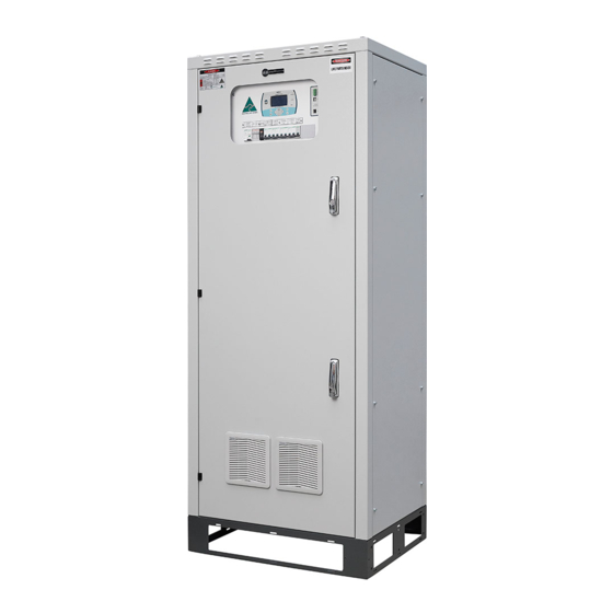
MCRII SERIES
BATTERY CHARGER
SINGLE PHASE MCRII SERIES BATTERY CHARGER
Rev: 1.15
22/08/2018
Doc: MAN-1P_MCRII
Page 1 of 36
THIS MANUAL SHOULD REMAIN WITH EQUIPMENT
Australian Technology – Australian Made
64 Bushland Ridge, Bibra Lake, WA 6163 P: +61 8 9434 6621 F: + 61 8 9434 6623
sales@magellanpower.com.au
www.magellanpower.com.au
E:
W:
Advertisement
Table of Contents

Related Manuals for Magellan Power MCRII Series

Summary of Contents for Magellan Power MCRII Series
- Page 1 OPERATION MAINTENANCE MANUAL SINGLE PHASE MCRII SERIES BATTERY CHARGER SINGLE PHASE MCRII SERIES BATTERY CHARGER Rev: 1.15 22/08/2018 Doc: MAN-1P_MCRII Page 1 of 36 THIS MANUAL SHOULD REMAIN WITH EQUIPMENT Australian Technology – Australian Made 64 Bushland Ridge, Bibra Lake, WA 6163 P: +61 8 9434 6621 F: + 61 8 9434 6623 sales@magellanpower.com.au...
-
Page 2: Table Of Contents
OPERATION AND MAINTENANCE MANUAL SINGLE PHASE MCRII SERIES BATTERY CHARGER OPERATION AND MAINTENANCE MANUAL Table of Contents INTRODUCTION ..................... 5 GENERAL SPECIFICATIONS ................6 AC INPUT ......................6 DC OUTPUT ......................6 LOAD REGULATION ................... 6 OPERATING ENVIRONMENT ................6 ALARMS........................ - Page 3 OPERATION AND MAINTENANCE MANUAL SINGLE PHASE MCRII SERIES BATTERY CHARGER CHECKING BATTERY CURRENT LIMITS ............. 31 CHECKING CHARGER CURRENT LIMIT ............31 TESTING MAINS FAIL ALARM ................ 32 TESTING DC LOW ALARM ................32 TESTING DC HIGH ALARM ................33 7.10...
- Page 4 OPERATION AND MAINTENANCE MANUAL SINGLE PHASE MCRII SERIES BATTERY CHARGER SAFETY PRECAUTIONS DANGER! • This equipment contains high DC and AC voltages. Do not work on live equipment unless authorised. • Isolate AC and DC before working on the equipment. Battery voltage may be present even when mains is isolated.
-
Page 5: Introduction
SINGLE PHASE MCRII SERIES BATTERY CHARGER 1.0 INTRODUCTION The Magellan Powertronics MCRII Series single phase battery charger / DC power system utilises phase controlled AC to DC conversion technique together with the latest micro-processor hardware and software to produce advanced charging systems suitable for Lead Acid, Nickel-Cadmium or Lithium Iron batteries. -
Page 6: General Specifications
OPERATION AND MAINTENANCE MANUAL SINGLE PHASE MCRII SERIES BATTERY CHARGER 2.0 GENERAL SPECIFICATIONS AC INPUT: Voltage: 240V ±10%, Single Phase Frequency: 50Hz ±5% Current: As per model DC OUTPUT: Nominal: As per model (see test sheet) Float: As per model (see test sheet) -
Page 7: Alarms
OPERATION AND MAINTENANCE MANUAL SINGLE PHASE MCRII SERIES BATTERY CHARGER 2.5 ALARMS Mains Fail No Adjustment Charger Fail No Adjustment Low Electrolyte No Adjustment (for vented batteries only) Battery Disconnected No Adjustment Battery Fail As per model (software adjustable) DC Low... -
Page 8: Controls
OPERATION AND MAINTENANCE MANUAL SINGLE PHASE MCRII SERIES BATTERY CHARGER Battery Over Voltage Mains Trip (optional) 2.8 CONTROLS The following adjustments can be done by the software: Float Voltage Adjustment Boost Voltage Adjustment Boost Timer Adjustment Charger Current Limit Adjustment... -
Page 9: Installation Instructions
OPERATION AND MAINTENANCE MANUAL SINGLE PHASE MCRII SERIES BATTERY CHARGER 3.0 INSTALLATION INSTRUCTIONS Install the battery charger in the allocated position and ensure that sufficient cooling air is available for natural convection cooling. 3.1 CABLING Refer to the Charger Schematic and Connection Diagram in the Appendix 1. -
Page 10: Circuit Description
OPERATION AND MAINTENANCE MANUAL SINGLE PHASE MCRII SERIES BATTERY CHARGER 4.0 CIRCUIT DESCRIPTION See Charger Schematic drawing in the Appendix The AC input voltage is applied to the power transformer (T1) primary winding via the input EMI filter and the input Circuit Breaker CB1. Transformer (T1) galvanically isolates the AC mains input from the DC output and converts the mains voltage into secondary voltage of the required levels for the power bridge (BR1). - Page 11 OPERATION AND MAINTENANCE MANUAL SINGLE PHASE MCRII SERIES BATTERY CHARGER (A2) de-energises if an alarm condition is detected. The common alarm signal also drives a buzzer located on the Microcontroller Board (A3). The buzzer sounds for any alarm condition and will stay on for the duration of the alarm. The buzzer can be...
-
Page 12: Operating Instructions
OPERATION AND MAINTENANCE MANUAL SINGLE PHASE MCRII SERIES BATTERY CHARGER 5.0 OPERATING INSTRUCTIONS 5.1 START UP The following start up procedure should be employed whenever starting the system after a total shutdown. 1) Switch on Battery Breaker CB3. This will cause the display to come on and go through the start-up sequence, briefly display the MAGELLAN logo and show the top page after a delay of a few seconds. - Page 13 OPERATION AND MAINTENANCE MANUAL SINGLE PHASE MCRII SERIES BATTERY CHARGER Screen 2 Charger voltage, Charger Current, Load Voltage, Load Current. Screen 3 Charger voltage, Charger Current, Battery Voltage, Thyristor Bridge. Screen 4 Charger voltage, Charger Current, Battery Temperature, Battery Current.
- Page 14 OPERATION AND MAINTENANCE MANUAL SINGLE PHASE MCRII SERIES BATTERY CHARGER Screen 5 Charger voltage, Charger Current, Battery AH Capacity, Last AH Ratio (in % of expected capacity). Rev: 1.15 22/08/2018 Doc: MAN-1P_MCRII Page 14 of 36 Australian Technology – Australian Made 64 Bushland Ridge, Bibra Lake, WA 6163 P: +61 8 9434 6621 F: + 61 8 9434 6623 sales@magellanpower.com.au...
-
Page 15: Boost Charging Batteries
OPERATION AND MAINTENANCE MANUAL SINGLE PHASE MCRII SERIES BATTERY CHARGER Mode/Ack Cycling through these screens is achieved by operating the switch on the front panel. The display will automatically return to Screen 1 in 5 minutes if left on Screen 2 to 5. - Page 16 OPERATION AND MAINTENANCE MANUAL SINGLE PHASE MCRII SERIES BATTERY CHARGER When the difference between the measured impedance and the Baseline Impedance is greater than 75% of the Baseline Impedance, the Battery Fail Alarm will be activated. 5.4.2 MODE 2: Discharge Test The Discharge Test operates by discharging the battery into a load that is connected across the battery for 5 minutes.
-
Page 17: Temperature Compensation
OPERATION AND MAINTENANCE MANUAL SINGLE PHASE MCRII SERIES BATTERY CHARGER 5.4.3.1 PROCEDURE: 1) Press and hold ‘BATT TEST’ button for more than 10 seconds. 2) Display goes automatically to Capacity and Last ratio menu, and alternately shows Battery Impedance and Baseline mOhms, and then Capacity and Battery Amps. - Page 18 OPERATION AND MAINTENANCE MANUAL SINGLE PHASE MCRII SERIES BATTERY CHARGER Under voltage trip is always non-latching, as it also drives an auxiliary relay whose function is to reconnect the battery as soon as the charging system returns to normal. (This is an optional feature) (See Alarm Operational Description).
- Page 19 OPERATION AND MAINTENANCE MANUAL SINGLE PHASE MCRII SERIES BATTERY CHARGER Mode Pressing the key will now display the charging rate at which the charger will Arrow operate while in constant current mode. Adjust by using the keys (if necessary). Pressing the battery test key will initiate constant current mode. The charger will remain in this mode until the preset time has elapsed.
-
Page 20: Adjustments
OPERATION AND MAINTENANCE MANUAL SINGLE PHASE MCRII SERIES BATTERY CHARGER 6.0 ADJUSTMENTS The Programmable Setpoints can be programmed either from the Keypad LCD panel or from a computer connected to the charger through the communication card. Some of the settings are password protected to prevent unauthorised changes from being implemented. -
Page 21: Programmable Set Point Descriptions
OPERATION AND MAINTENANCE MANUAL SINGLE PHASE MCRII SERIES BATTERY CHARGER 6.3 PROGRAMMABLE SET POINT DESCRIPTIONS Following is a description of the function each adjustable set point. Sub Menu 1 Float and Boost Charging Settings The following set points are used to set the charger output voltage settings and to set the boost operational parameters. - Page 22 OPERATION AND MAINTENANCE MANUAL SINGLE PHASE MCRII SERIES BATTERY CHARGER Sub Menu 2 Alarm and Trip Settings The following parameters are used for setting alarm and over/under voltage trip and delay times. Hi Voltage Alarm Sets activation voltage of the DC High alarm.
- Page 23 OPERATION AND MAINTENANCE MANUAL SINGLE PHASE MCRII SERIES BATTERY CHARGER 6.3.1 Sub Menu 3 Diode Dropper Settings A Diode Dropper may be used to further regulate the load voltage. (This feature is optional). The following parameters are used for setting the switch-in and switch-out voltages for the diode droppers.
- Page 24 OPERATION AND MAINTENANCE MANUAL SINGLE PHASE MCRII SERIES BATTERY CHARGER Sub Menu 5 Latches and Inhibit Settings The following set points program alarm latches and control selected alarm inhibits. Earth Fault Inhibit Inhibits the earth fault alarm. Low Electrolyte Inhibit Inhibits the low electrolyte alarm.
- Page 25 OPERATION AND MAINTENANCE MANUAL SINGLE PHASE MCRII SERIES BATTERY CHARGER 6.3.4 Sub Menu 7 Charger and Battery Definition Set up Note: This menu is password protected. Adjustment should only be made in consultation with Magellan Powertronics. The following set points are used to set the MCRII Controller to match the charger hardware (Charger and battery size and type).
- Page 26 OPERATION AND MAINTENANCE MANUAL SINGLE PHASE MCRII SERIES BATTERY CHARGER To calibrate each setting, it is necessary to connect a calibrated meter in circuit to measure the required meter function. The set point should then be adjusted by the front panel arrow keys, so the set point equals the external calibrated meter measurement.
- Page 27 OPERATION AND MAINTENANCE MANUAL SINGLE PHASE MCRII SERIES BATTERY CHARGER 6.3.7 Sub Menu 10 Diagnostic Set up This sub menu is used to put the charger into a self-diagnostic mode. Diagnostic Level 1 Setting to On enables the level 1 diagnostic.
-
Page 28: Earth Fault Alarm
OPERATION AND MAINTENANCE MANUAL SINGLE PHASE MCRII SERIES BATTERY CHARGER 6.3.8 Sub Menu 11 Current Limit Set up This sub menu is used to set the charger and battery current limits. Note: This menu is password protected. Adjustment should only be made in consultation with Magellan Powertronics. - Page 29 PROGRAMMING MODE SETTING PRESS (-), (+) and MODE/ACK KEYS SIMULTANEOUSLY FOR 5 SECONDS. THE CPU BOARD WILL NOW SWITCH OVER TO PROGRAMMING/CALIBRATION MODE. PRESS (BACK) KEY TO REVERT TO NORMAL OPERATION ONCE PROGRAMMING IS COMPLETED. 1.0 M 6.5.1 6.5.2 6.5.3 6.5.4...
-
Page 30: Commissioning
OPERATION AND MAINTENANCE MANUAL SINGLE PHASE MCRII SERIES BATTERY CHARGER 7.0 COMMISSIONING 7.1 START-UP Before delivery the charger is factory adjusted in accordance with the test sheets. The actual Setpoints loaded are recorded in the test sheet. The factory settings for float and boost rate charge volts are calculated to correspond with the number and type of battery cells. -
Page 31: Checking Boost Voltage
OPERATION AND MAINTENANCE MANUAL SINGLE PHASE MCRII SERIES BATTERY CHARGER 7.4 CHECKING BOOST VOLTAGE With the charger set to boost, connect a precision voltmeter across output terminals and take a reading. If adjustment is required refer to the adjustments section. -
Page 32: Testing Mains Fail Alarm
OPERATION AND MAINTENANCE MANUAL SINGLE PHASE MCRII SERIES BATTERY CHARGER 7.7 TESTING MAINS FAIL ALARM Simulate a mains failure by isolating the charger at the AC supply distribution board. Mains Fail After a delay the LED will be lit. Check that the mains fail relay on the Relay board A4 (if fitted) has de-energised and that its contacts (see Schematic Diagram) have changed over. -
Page 33: Testing Dc High Alarm
OPERATION AND MAINTENANCE MANUAL SINGLE PHASE MCRII SERIES BATTERY CHARGER 7.9 TESTING DC HIGH ALARM Disconnect all loads from the charger. Increase the Float voltage (See User Adjustable Set Point Instruction Sheet) to a setting just above the DC High level. The... -
Page 34: Testing Low Electrolyte
OPERATION AND MAINTENANCE MANUAL SINGLE PHASE MCRII SERIES BATTERY CHARGER 7.10 TESTING LOW ELECTROLYTE Ensure the Low Electrolyte Alarm is not inhibited. Low Electrolyte Remove the electrolyte probe (if fitted) and check for fault indication on the LCD panel. Check that the low electrolyte relay on the Relay board A4 (if fitted) has de-energised and that its contacts (see Schematic Diagram) have changed over. - Page 35 OPERATION AND MAINTENANCE MANUAL SINGLE PHASE MCRII SERIES BATTERY CHARGER Magellan Power Service Department The Magellan Power Service Department has been formed to offer customers peace of mind when it comes to reliability of back-up power with presence in WA and Australia wide.
- Page 36 OPERATION AND MAINTENANCE MANUAL SINGLE PHASE MCRII SERIES BATTERY CHARGER Australian Technology – Australian Made 64 Bushland Ridge, Bibra Lake, WA 6163 P: +61 8 9434 6621 F: + 61 8 9434 6623 sales@magellan-power.com.au www.magellan-power.com.au...
Need help?
Do you have a question about the MCRII Series and is the answer not in the manual?
Questions and answers
Float charge Sensor disconnect
When the sensor is disconnected, the float charge procedure for the Magellan Power MCRII Series involves readjusting the Float voltage to the level shown on the test report and then reconnecting the battery.
This answer is automatically generated
Comms fail