
Related Manuals for Schweitzer Engineering Laboratories SEL-2020

Summary of Contents for Schweitzer Engineering Laboratories SEL-2020
- Page 1 SEL-2020 COMMUNICATIONS PROCESSOR INSTRUCTION MANUAL SCHWEITZER ENGINEERING LABORATORIES, INC. 2350 NE HOPKINS COURT PULLMAN, WA USA 99163-5603 TEL: (509) 332-1890 FAX: (509) 332-7990...
- Page 2 CAUTION: ATTENTION: Never work on the SEL-2020 with the Ne jamais travailler sur le SEL-2020 front or top cover removed, when the SEL-2020 is avec le panneau avant ou du dessus enlevé, quand le energized. SEL-2020 est sous-tension. CAUTION: ATTENTION: There is danger of explosion if the battery Il y a un danger d’explosion si la pile...
-
Page 3: Date Code
Section 6, Set G – Global Settings - Additions Section 6, Table 6.17 - Additions Section 6, Table 6.18 - Additions Appendix A, Firmware Versions - Additions Appendix I, Internal Indication Object - Additions Date Code 20010518 Manual Change Information SEL-2020 Instruction Manual... - Page 4 Section 9, Port Status Register - Additions Appendix A, Firmware Versions - Additions Appendix E, Table E.1 & E.4 - Additions Appendix F, SEL-2020 Compatibility - Additions Appendix G, Modbus Protocol - Additions Appendix H, Fast Operate Configuration - Clarification Appendix I, Table I.2 - Additions...
- Page 5 Date 971029 Appendix A, Firmware Versions - Additions Appendix E, Table E.1 & E.4 - Additions Appendix F, SEL-2020 Compatibility - Additions Appendix G, Modbus Protocol - Additions 970825 Section 8, Table 8.2 - Additions Section 8, SEL-2020 Strings - Additions Appendix E, Table E.2 - Clarifications...
- Page 6 Section 3, Alarm Contact Connection - Clarification Section 4, Figure 4.8 - Clarification Section 4, Example 6, Operation - Clarification Section 4, Example 6, Set the SEL-2020, Step-By-Step - Addition in 3b screen capture Section 4, Example 9, Set the SEL-2020, Step-By-Step - Clarification Section 5, Table 5.1 - Add DEFRAG command...
- Page 7 Appendix E, Table E.1 - Addition of new relays Appendix E, Table E.4 - Addition of new relays Appendix F, SEL-2020 Compatibility - Addition of new relays Appendix G, Hardware Connections and RTS Line Usage - Additions Appendix G, Message Framing - Additions in Read Coil Status, Clarification in Force Single Coil Appendix G, Table G.1 - Clarification in SEL-279, Addition of new relays,...
- Page 9 Appendix A: Firmware Versions Appendix B: Optional Internal Modem Information Appendix C: LMD Protocol Appendix D: ASCII Reference Table Appendix E: Planning Sheets Appendix F: SEL-2020 Compatibility ® Appendix G: Modbus Protocol Appendix H: Configuration and Fast Operate Commands Appendix I: Distributed Network Protocol (DNP) V3.00...
-
Page 11: Table Of Contents
TABLE OF CONTENTS SECTION 1: INTRODUCTION Overview of the Manual........................1-1 Background Information .......................1-1 Section Highlights .........................1-2 Appendices ..........................1-2 List of Acronyms, Abbreviations, and Glossary Terms..............1-3 Initial Checkout..........................1-3 Data Sheet Introduction Date Code 20010518 SEL-2020 Instruction Manual... -
Page 13: Section 1: Introduction
Processor is designed to meet that goal. We appreciate your interest in SEL products and we are dedicated to making sure you are satisfied. If you have any questions about the SEL-2020 or the manual, please contact us at : Schweitzer Engineering Laboratories, Inc. -
Page 14: Section Highlights
• Section 8: Message Strings, provides information about the characters, and pre-defined strings that you can use in a number of SEL-2020 settings. At the end of this section and also on a blue pull-out card at the end of the book is a summary list of special characters and pre-defined strings. -
Page 15: List Of Acronyms, Abbreviations, And Glossary Terms
1. Visually inspect the SEL-2020 for loose or damaged parts. 2. Connect and apply power to the SEL-2020. (See the PWR SUP field on the rear-panel nameplate for power requirements.) If you do not have the proper voltage source available, use a power supply, like the SEL-LPS, to power the unit. - Page 16 The status and communications statistics are shown for the 16 rear-panel ports and the front-panel port. Refer to the STATUS command explanation in Section 5: Commands for more detailed information. Introduction Date Code 20010518 SEL-2020 Instruction Manual...
- Page 17 Active 100% None *>> Refer to the SEL-2020 Data Sheet in this section of the instruction manual, and Section 2: General Description for more information about the operation and features of the SEL-2020. Date Code 20010518 Introduction SEL-2020 Instruction Manual...
-
Page 19: Data Sheet
SEL-2020 Communications Processor Data Sheet General Description: The SEL-2020 Communications Processor is a breakthrough for substation communication and integration. It combines multiport communications, databases and processing, nonvolatile memory, timekeeping and synchronization, alarm monitoring, and auxiliary control into one compact, powerful, economical, easy-to-use, and rugged device. - Page 20 (SER), digital meters, and digital relays. The SEL-2020 can function as a simple, but intelligent, port switch. Or it can provide sophisticated communication and data handling capability required for advanced substation integration projects.
- Page 21 SEL-2020; no proprietary software is needed unless it is required by non-SEL IEDs. You can program each SEL-2020 port that is connected to a modem to dial out through the modem to deliver messages, event reports, and other information to computers at remote locations.
- Page 22 SEL-321 SEL-351A SEL-311C SEL-351A SEL-321 SEL-311C SEL-587 SEL-351 SEL-351A SEL-351A SEL-2020 Communications IRIG-B Processor Time Receiver Telephone Line SCADA Printer Local User Interface DWG: ds2020-001.vsd Figure 1: SEL-2020 Example Configuration Diagram...
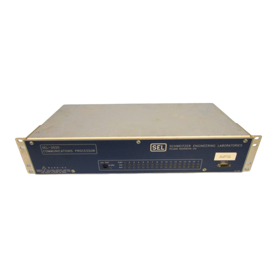
- Page 23 Figure 2: SEL-2020 Front and Rear Panels...
- Page 24 Generator to make a response based on the SEL-2020 settings that you have defined. When you use the SEL-2020 as a port switch, the Input Handler places collected data in the Data Area, and the Message Generator reads and outputs these data to a designated port. The Input Handler also stops communication when it recognizes the default termination condition or a termination condition you have defined in settings.
- Page 25 For example, receiving a summary event report could trigger the SEL-2020 to send the EVENT command back to the relay. The relay would respond with the long event report, and the SEL-2020 could then save it. You can store the data in volatile RAM or in the optional nonvolatile archive memory.
- Page 28 PECIFICATIONS Output Contacts Make: 30 A Carry: 6 A continuous carry at 70°C, 4 A continuous carry at 85°C One-second rating: 50 A MOV protected: 270 Vac, 360 Vdc, 40 J Pickup time: Less than 5 ms Dropout time: Less than 5 ms, typical. Breaking Capacity (10,000 operations): 24 V 0.75 A...
- Page 29 Connector: Female BNC. Time Code: Modulated IRIG-B 1000 Vdc isolation. Demodulated IRIG-B TTL-compatible. Automatically sets SEL-2020 real-time clock/calendar. Time-Code Output Pinout: Pin 4 TTL-level signal. Pin 6 Chassis ground reference. Connectors: All 16 rear DB-9 port connectors. Outputs are generated from IRIG-B input (when present) or generated by CPU from real-time clock/calendar.
- Page 30 IRIG-B receiver or local clock. Use Events to Switch Relay Setting Groups Program the SEL-2020 to use the time of day, day of the week, or a specific event, such as a relay alarm output, to switch relay setting groups.
- Page 31 Connect a computer to the SEL-2020 through the computer serial port. Using your own human- machine interface (HMI) software, you can build screens and specify the HMI data definition. You can create commands that instruct the SEL-2020 to send selected data to the standard serial port interface for the HMI package.
- Page 32 OGIC facilitated using String and Expression Builders in the SEL-5020. While special software is not required to communicate with and set the SEL-2020, the SEL-5020 can be a valuable tool, especially when programming multiple SEL-2020s. Figure 5: SEL-2020 Dimensions, and Drill Plan for Rack-Mount Model...
- Page 33 Figure 6: SEL-2020 Panel Cutout and Drill Plan for Panel-Mount Models...
- Page 34 ACTORY SSISTANCE The employee-owners of Schweitzer Engineering Laboratories are dedicated to making electric power safer, more reliable, and more economical. We appreciate your interest in SEL products, and we are committed to making sure you are satisfied. If you have any questions, please contact us at:...
- Page 35 Non-“20” Message Response ..................2-12 Simple Settings..........................2-12 SET G - Global Settings......................2-12 SET P - Port Configuration Choices (Ports F, 1-16)............2-12 U (Unused) ........................2-13 S (SEL IED).........................2-13 O (Other IED)......................2-13 P (Printer) ........................2-13 M (Master)........................2-13 General Description Date Code 20010518 SEL-2020 Instruction Manual...
- Page 36 SET M - Data Movement (Ports 1-16) ................2-16 SET L - Logic (Ports 1-16)....................2-16 SET C - Calibration......................2-16 “Job Done” Example........................2-17 “Job Done!”..........................2-21 SEL-2020 Robust Design......................2-21 Wide Temperature Operating Range...................2-21 Wide Voltage Range Power Supply..................2-21 Meets Tough IEEE & IEC Standards..................2-22 User-Friendly Features........................2-22 Auto-Help..........................2-22...
- Page 37 TABLES Table 2.1: SEL-2020 Global Elements .....................2-7 Table 2.2: SEL-2020 Local Elements for Each Port.................2-8 FIGURES Figure 2.1: SEL-2020 Database Structure ....................2-6 General Description Date Code 20010518 SEL-2020 Instruction Manual...
-
Page 39: Section 2: General Description
SEL-2020’s features and their benefits to the user. ASIC OWERFUL UNCTIONS The SEL-2020's unique design and powerful features make it useful for a variety of functions. It can serve as an intelligent port switch, a synchronizing time source, a communications processor, ® a SEL Control Equations programmable controller, and an automatic database. -
Page 40: Intelligent Port Switch
NTELLIGENT WITCH You can configure the SEL-2020 as a port switch simply by using the SET P command to activate and configure each port that has a device connected. Port F on the front and Port 8 on the rear panel are configured as Master ports at the factory, so you can connect your PC or terminal to either of these to communicate with the SEL-2020. -
Page 41: Auto-Configuration
SEL-2020 port using a special cable designed for both communication and IRIG-B signal. For devices that do not have an IRIG-B port or cannot decode the IRIG-B signal, the SEL-2020 can send time and date messages on a periodic or time basis to keep their clocks synchronized. -
Page 42: Receive Messages And Data
SEL relay auto-messages. (See Section 6: Settings.) Modbus Protocol. You can select Ports 12, 14, and 16 of an SEL-2020 as Modbus ports. The network master (receiver) can access the database of all SEL-2020 ports through a Modbus port. -
Page 43: Sel Ogic Control Equations Programmable Controller
These capabilities offer substantial advantages. Fast Meter data received from SEL relays consist of raw voltage and current samples. In many cases, the SEL-2020 calculates more output quantities from the raw data than the SEL relay that sampled the original data; these additional output quantities include current and voltage phasor angles, per-phase megawatts and megavars, and complete sequence components. -
Page 44: Automatic Database
ATABASE Database Structure The SEL-2020 Data Area includes a database structured as shown in Figure 2.1 consisting of the following defined regions: Global (GLOBAL), Local (LOCAL), Buffer (BUF), Data (D1-D8), Archive (A1-A3), and User (USER). For a more complete description of the database, see Section 9: Database. -
Page 45: Local Region
OUT4 Row 0: Day-of-Week elements, SUN through SAT; one is asserted each day of the week; and external IRIG-B status element is asserted when the SEL-2020 detects the external IRIG-B signal. Row 1: Intermediate Variable elements, V, W, X, Y, and Z, are asserted when the corresponding intermediate logic equation is true;... - Page 46 Control Equation, such as OGIC requesting data or issuing a control command. Table 2.2 lists the SEL-2020 Local elements associated with each port. A brief description of these elements and their function follows the table. Table 2.2: SEL-2020 Local Elements for Each Port...
-
Page 47: Buf Region
AUTOBUF to Yes. The buffer accumulates messages until it is full, at which point the newest message overwrites the oldest message. The buffer can be read and cleared in a number of ways both manually and automatically. Date Code 20010518 General Description SEL-2020 Instruction Manual... -
Page 48: D1 To D8 Regions
For all ports, except the front port, the database includes data regions D1 to D8, allocated for data solicited by the SEL-2020. The first four registers of each region hold the date and time the data were collected. The remainder of each region is for the collected data. How the information is parsed, or separated into useful groups, will depend on the type of data and how it is collected. -
Page 49: Auto
When this com- mand is applied to a port, the SEL-2020 responds with a list of database regions, their data names, and the number of archive records. You can also use the MAP command to look at the database structure within a region. -
Page 50: 20" Message Response
IMPLE ETTINGS There are seven SET command variations you can use to configure and control the SEL-2020’s operation. These include SET G for global settings, SET P for port configuration and communi- cation settings, SET A for automatic messages, SET U for user-defined commands, SET M for... -
Page 51: U (Unused)
S (SEL IED) The S response indicates that an SEL relay or SEL-2020 is connected to the port (for other SEL devices, such as a PRTU, select O for Other IED). The SEL-2020 then asks you if the SEL-2020 should perform an auto-configuration with the relay on the port. -
Page 52: Autobuf
CONTROL), as determined during auto-configuration, with the breaker (BR1 - BR16) and remote bit (RB1 - RB16) elements. MSG_CNT With the MSG_CNT setting you enter a number from 0 to 12 to tell the SEL-2020 how many messages you plan on setting for a given port. ISSUEn... -
Page 53: Numn
NUMn If you choose to store the unrecognized data using one of the parsing options in the PARSEn setting, the SEL-2020 will prompt you to set a limit on the amount of data stored using the NUMn setting. DELAYn This setting is used with non-“20” messages to determine the method for detecting the end of the incoming message. -
Page 54: Nackn
(SBR1 - SBR16, SRB1 - SRB16, CBR1 - CBR16, and CRB1 - CRB16). SET C - Calibration There is normally no need for you to calibrate the SEL-2020 because it is fully calibrated at the factory. Calibration checks are only needed if you change EPROMs to upgrade the SEL-2020 firmware, and even then it is unlikely that any changes will be needed. -
Page 55: Job Done" Example
Port 1 on the SEL-2020. 2. Access Level 2 on the SEL-2020 and issue the command SET P 1 to configure Port 1. The SEL-2020 will prompt for the type of device connected to the port. Enter S for SEL IED, Y to auto-configure the port, and press the <ENTER>... - Page 56 '*' next to its port number: Port F in the current example. b) Verify the location and type of data being collected on Port 1 of the SEL-2020 by issuing the command string MAP 1. The SEL-2020 responds with a database map of the Port 1 data regions.
- Page 57 SEL-2020 by issuing the command string MAP 1:METER or MAP 1:D1. The SEL-2020 responds with a map of the specific data region, including a listing of the data item names, the starting address for each data item, and the type of data stored at each address.
- Page 58 In this example, the SEL-251 Relay is connected to the SEL-2020’s Port 1, which is shown with active status and 100% communication success rate. If the relay is disconnected or turned off, the status changes to inactive.
-
Page 59: Job Done
SEL-2020 R OBUST ESIGN The SEL-2020 is designed to provide reliable service in a wide variety of electrical, physical and environmental conditions. Wide Temperature Operating Range The SEL-2020 is designed for operation with an ambient temperature between -40° and +85°C (-40°... -
Page 60: Meets Tough Ieee & Iec Standards
The command has an option to copy settings from one port to all ports, but the SEL-2020 requests confirmation of the copy function for each port before performing the copy operation. -
Page 61: Options
Flexible communications parameters make the SEL-2020 a great choice for almost any port switching application. The multi-tasking/multi-user capability and data handling capability make the SEL-2020 more of a self-contained network hub than a port switch, but it is still an economical choice for port switching applications. The time synchronization capabilities of the SEL-2020 add to its value in this application. -
Page 62: Scada Interface
SCADA Interface The SEL-2020 can be interfaced with a variety of devices, including RTUs. The SEL-2020 can serve as a data concentrator, to be polled by a local RTU, or it can be connected to a dedicated SCADA communication circuit and polled by a central device. - Page 63 Installation...........................3-13 TABLES Table 3.1: Serial Port Connector Pin Definitions ..................3-4 Table 3.2: Communication Cables for Devices Attached to SEL-2020 ...........3-5 Table 3.3: SEL-2020 Minimum Data Collection Period (in Seconds) .............3-9 Table 3.4: Main Board Jumper Positions....................3-10 Table 3.5: Optional I/O Board Control Input Voltage Selection Jumper Positions........3-11 Table 3.6: Optional I/O Board Contact Form Jumper Positions.............3-11...
- Page 64 FIGURES Figure 3.1: 9-Pin Connector Pin Number Convention (female chassis connector, as viewed from outside panel) .........................3-3 Figure 3.2: SEL-2020 Main Board Jumper Location................3-15 Figure 3.3: SEL-2020 Optional I/O Board Jumper Location..............3-16 Installation Date Code 20010518 SEL-2020 Instruction Manual...
-
Page 65: Section 3: Installation
(POW SUP) characteristics specified on the rear panel nameplate of your SEL-2020. If you provide a dc power source, you must connect the source with the proper polarity as indicated by the “+” and “−” labels on the power terminals. The SEL-2020 internal power supply has very low power consumption and a wide voltage tolerance. -
Page 66: Irig-B Input Connection
SEL-2020. See Table 3.4 and Figure 3.2 for the main-board jumper positions to select the appropriate type of IRIG-B input signal. The factory default setting is demodulated IRIG-B time input. -
Page 67: Communication Circuit Connections
“PORT 1” through “PORT 16”, and one front panel serial communication port, labeled “PORT F”. The data connection for each SEL-2020 serial communication port uses EIA-232 standard signal levels in a 9-pin, subminiature “D” connector (see Figure 3.1 and Table 3.1). -
Page 68: Communication Cables
*When internal jumper is installed. Communication Cables Standard SEL communication cables available for your use with the SEL-2020 are listed in Table 3.2. Using an improper cable can cause numerous problems, so you must be sure to specify the proper cable for the application. Please call the SEL factory if you have any questions about cables and cable connections. - Page 69 Table 3.2: Communication Cables for Devices Attached to SEL-2020 Remote Connector Port RTS/CTS IRIG-B Connect SEL-2020 to: Cable # (on cable) Type Supported Included C157A Existing SEL-PRTU Relay Cable retrofit 9-pin Con-X-All (female) C222 25-pin DCE devices: DB-25P Standard modem,...
-
Page 70: Communications
We recommend the SEL-2810 Fiber-Optic Modem for these applications. The connection between the SEL-2020 and the modem is EIA- 232. The connection between the remote modem and the remote device is also EIA-232. Optical fibers connect the two modems. -
Page 71: Telephone Line Communications
+5 Vdc power. The total current drawn by all of the external modems powered by one SEL-2020 should not exceed 0.5 amp. See Table 3.4 and Figure 3.2 for the +5 Vdc power jumper settings for each port. None of these jumpers are installed at the factory. -
Page 72: Baud Rate
Baud Rate The default baud rate for the SEL-2020 front port, Port F, is 2400 baud. You can change the Port F baud rate, and the other Port F communication parameters using the SET P command. You can force the Port F baud rate to 2400 baud by hardware jumper selection (see Table 3.4). - Page 73 If the data response has not been completed before the same message trigger condition occurs again, the second trigger will be missed completely. The SEL-2020 will acknowledge this missed trigger by setting a delay bit in the port register, which is reported in the SEL-2020 status report.
-
Page 74: Jumper Settings
Reserved - Do not install JMP9 D Input/Output Connections If your SEL-2020 is equipped with the optional I/O board, it has a terminal strip that extends nearly the full width of the SEL-2020, near the top of the rear panel. 3-10... -
Page 75: Configure The Inputs For 48 V, 125 V Or 250 V
Configure the Output Contact Form The SEL-2020 I/O board is shipped from the factory with form A output contacts. You may reconfigure the contacts by desoldering and then resoldering the 20 AWG jumper wire for each contact. Table 3.6 and Figure 3.3 show the jumper positions required to configure the contacts. -
Page 76: Open The Sel-2020 To Access Internal Jumpers
Open the SEL-2020 to Access Internal Jumpers After you have decided on the appropriate SEL-2020 hardware configuration, you are ready to reconfigure the SEL-2020 if the default configuration does not meet your needs. Perform the following steps to gain access to internal jumpers: 1. -
Page 77: Installation
Replace the front panel and front-panel screws and tighten them securely. NSTALLATION Before you install the SEL-2020, you should perform the initial checkout procedure found in Section 1: Introduction, and set the configuration jumpers according to your installation requirements per the instructions outlined earlier in this section. Install the SEL-2020 according to the following step-by-step instructions: Mount the SEL-2020 in the desired panel location. - Page 78 Inactive None Inactive None Inactive None Inactive None Inactive None Active None Active None Inactive None Inactive None Inactive None Inactive None Inactive None Inactive None Inactive None Active 100% None *> 3-14 Installation Date Code 20010518 SEL-2020 Instruction Manual...
- Page 79 Figure 3.2: SEL-2020 Main Board Jumper Location Date Code Code 20010518 Installation 3-15 SEL-2020 Instruction Manual...
- Page 80 Figure 3.3: SEL-2020 Optional I/O Board Jumper Location 3-16 Installation Date Code 20010518 SEL-2020 Instruction Manual...
- Page 81 TABLE OF CONTENTS SECTION 4: “JOB DONE” EXAMPLES Introduction ...........................4-1 Example 1: Using the SEL-2020 as a Port Switch...............4-3 Introduction ...........................4-3 Identifying the Problem.........................4-3 Defining the Solution ........................4-4 Complete Hardware Connections..................4-4 Set the SEL-2020........................4-4 Verify and Test All Communication Paths ................4-4 Set the SEL-2020, Step-By-Step ....................4-5...
- Page 82 Defining the Solution ........................4-67 Set the SEL-2020 Step-by-Step....................4-67 Test the Operation........................4-69 FIGURES Figure 4.1: SEL-2020 Configured with Seven SEL-251 Relays, Optional Modem, and IRIG-B Source ..........................4-3 Figure 4.2: SEL-2020 with Relays and Printers..................4-17 Figure 4.3: SCADA RTU Configuration Diagram .................4-25 Figure 4.4: Trigger P00:00:01 and 20METER Setting in SET A............4-27...
-
Page 83: Section 4: "Job Done" Examples
SECTION 4: “JOB DONE” EXAMPLES NTRODUCTION This section describes SEL-2020 operations and user interface with eight examples that include a variety of common applications. In this manual, commands you type appear in bold/uppercase: OTTER. Keys you press appear in bold/uppercase/brackets: <ENTER>. SEL-2020 output... - Page 84 (This Page Intentionally Left Blank) “Job Done” Examples Date Code 20010518 SEL-2020 Instruction Manual...
-
Page 85: Example 1: Using The Sel-2020 As A Port Switch
Also, you have SEL-C239 cables of the appropriate length to connect the SEL-2020 to each relay. You have a PC or terminal and an SEL-234A cable to communicate with the SEL-2020. You will connect all of these as shown in Figure 4.1, below. -
Page 86: Defining The Solution
4. Connect your computer’s serial port to the SEL-2020’s Port F with an SEL-C234A cable. Note: You do not need to modify the baud rate of Port 2 at the relay; the SEL-2020 will match the baud rate during auto-configuration. - Page 87 4. Check that the SEL-2020 issues the correct date code to each relay. Change the relay date to the wrong year; use the TOGGLE command to issue the SEL-2020 date message. 5. Check Modem Communication. Have someone call; the SEL-2020 modem should answer by the fourth ring.
- Page 88 Default TERSTRING = “\004” is ASCII hexadecimal code for keystroke <CTRL-D>. Use <CTRL-D> to end or quit transparent communication with a port. Review all settings and accept the changes by typing Y<ENTER>. “Job Done” Examples - (Example 1) Date Code 20010518 SEL-2020 Instruction Manual...
- Page 89 Notes: Type Y<ENTER> to auto-configure the port. Set port time-out to 30 minutes to automatically disconnect transparent communication. Accept new settings by typing Y <ENTER> to save changes. Date Code 20010518 “Job Done” Examples - (Example 1) SEL-2020 Instruction Manual...
- Page 90 This setting sequence uses the SET A command to set a message trigger and a message in Port 1 of the SEL-2020. This example sets the SEL-2020 to issue the date command to the relay attached to Port 1 once each day. Even though you supply IRIG-B time to the relays, if a relay is powered down for any reason it may need this date information to establish the current year because the year is not supplied by IRIG-B.
- Page 91 Port 1 Settings Changed *>> Notes: Set AUTOBUF=Yes to permit the SEL-2020 to collect and store unsolicited messages from the relay, like summary event reports and group switch reports. Leave automatic operate control disabled for this example. Set MSG_CNT=1 so SEL-2020 prompts for one message trigger and message.
- Page 92 Use the COPY 1 ALL as a shortcut to copy settings on Port 1 to all other ports. Port 8 is not permitted as a destination because it has an internal modem in this example. 4-10 “Job Done” Examples - (Example 1) Date Code 20010518 SEL-2020 Instruction Manual...
- Page 93 PC and the SEL-2020 internal modem will negotiate the highest possible baud rate, up to the 14400 baud maximum rate of the SEL-2020 internal modem if your PC has a modem capable of the same or higher baud rate.
- Page 94 AUTO_HELP= Y TERTIME1= 1 TERSTRING="\004" TERTIME2= OFF Save changes (Y/N) ? Y<ENTER> Y<ENTER> Y<ENTER> Y<ENTER> Port 8 Settings Changed *>> Note: Type Y<ENTER> to accept port setting changes. 4-12 “Job Done” Examples - (Example 1) Date Code 20010518 SEL-2020 Instruction Manual...
- Page 95 ATHS The remainder of this example verifies proper communication with the SEL-251 Relays attached to each port of the SEL-2020. 1. Issue the STATUS command to check that IRIG-B signal is present and devices are connected as expected. Your screen should look similar to the following: *>>STATUS<ENTER>...
- Page 96 “IRIG B DATA ERROR”. If you receive an error message, check the cable connection between the SEL-2020 and the relay AUX input port and consult the Troubleshooting Subsection in Section 10: Maintenance of this manual.
- Page 97 4. Use the TOGGLE command, as shown in the following screen image, to send the date message previously defined as MESG1 in the SEL-2020 As shown here, you toggle the state of the D1 element to trigger the associated message MESG1. The SEL...
- Page 98 Re-establish transparent communications with the relay and verify that the date matches the date in the SEL-2020. Use the DATE command to change the date and year in the relay (DATE MM/DD/YY); exit transparent communication and issue the TOGGLE command again.
- Page 99 SEL-2020 features and capabilities. The cable for the relay connected to the SEL-2020 Port 7 is replaced with a short-haul modem that supports communication, but not IRIG-B signal, and a serial printer is added to SEL-2020 Port 9.
-
Page 100: Set The Sel-2020
2. The computer connected to Port F and the configuration of Port F remain as in Example 1. 3. Connect a serial port printer to SEL-2020 Port 9 using an SEL-C223A cable or equivalent. Ports 1 through 8 of the SEL-2020 remain configured as in Example 1. - Page 101 The time entered in the command string, TIME 1:00:01, is set one second later than the ISSUE1 SEL Control Equation time to account for an expected one second delay in OGIC command transmission. Date Code 20010518 “Job Done” Examples - (Example 2) 4-19 SEL-2020 Instruction Manual...
- Page 102 Port 9 Settings Changed *>> Notes: Enter P to identify the device type as a printer. Enter an identification for the SEL-2020 port directory. Enter communication parameters compatible with the printer. 4-20 “Job Done” Examples - (Example 2) Date Code 20010518...
- Page 103 Your printer may require a power-up initialization. If it does, you enter it as a startup string. The startup string is issued to the printer when you power up the SEL-2020. You enable printing unsolicited messages and set the SEL-2020 to clear the unsolicited message buffers as the messages are printed.
- Page 104 This command was used in Example 1. You can also use the WHO command to see a list of all devices connected to SEL-2020 ports. The SEL-2020 response to the WHO command should look similar to the following screen image: *>>WHO<ENTER>...
- Page 105 This synchronization technique is not as accurate as with IRIG-B. You can expect the time on the relay to be synchronized within three seconds of the SEL-2020 clock. Date Code 20010518 “Job Done” Examples - (Example 2) 4-23 SEL-2020 Instruction Manual...
- Page 106 (This Page Intentionally Left Blank) 4-24 “Job Done” Examples - (Example 2) Date Code 20010518 SEL-2020 Instruction Manual...
- Page 107 RTU requests data at 1.5 second intervals. EFINING THE OLUTION The solution is to use the automatic database features of the SEL-2020. Figure 4.3 shows the SEL-2020 installation, with the RTU connected to Port 11. Date Code 20010518 “Job Done”...
-
Page 108: Set The Sel-2020
Complete Hardware Connections 1. The SEL-251 Relays remain configured as in the previous example. 2. Connect the EIA-232 port on the RTU to Port 11 of the SEL-2020 with a proper communication cable. 3. Retain the configuration for SEL-2020 Ports 1 through 9 from previous examples. - Page 109 (once each second in the example) it sets the D2 trigger bit. The Message Generator detects the D2 bit set and issues MESG2. You previously set MESG2 = 20METER using the SET A command. The SEL-2020 is programmed to send the METER command appropriate for the connected SEL relay.
-
Page 110: Verify And Test All Communication Paths
Settings DWG: 2020_25.vsd An RTU attached to Port 11 sends the GETDAT command to the SEL-2020. You previously defined this command (CMD1="GETDAT") using the SET U command. The Input Handler detects GETDAT and asserts the 11:CMD1 bit in the database. - Page 111 Enter an ID to indicate this port is connected to an RTU. Accept the default baud rate and associated communication parameters if they are compatible with the RTU. If these parameters are not compatible, make changes as necessary. Date Code 20010518 “Job Done” Examples - (Example 3) 4-29 SEL-2020 Instruction Manual...
- Page 112 PARSE1 = 0 DELAY1 = ON ISSUE2 = P00:00:01.0 MESG2 = 20METER ARCH_EN = N USER Save changes (Y/N) ? Y<ENTER> Y<ENTER> Y<ENTER> Y<ENTER> Port 1 Settings Changed *>> 4-30 “Job Done” Examples - (Example 3) Date Code 20010518 SEL-2020 Instruction Manual...
- Page 113 You do not need to perform auto-configuration if all port devices are identical. However, you may need to reset port IDs on all ports that settings are copied to, if port IDs were different on each port. Date Code 20010518 “Job Done” Examples - (Example 3) 4-31 SEL-2020 Instruction Manual...
- Page 114 4. Define a command (GETDAT) that the RTU will send to the SEL-2020 to request meter data (see Figure 4.5). Use SET U to define this user-defined command (CMD1="GETDAT"). Your screen should show the following: *>>SET U 11<ENTER> SET U 11<ENTER>...
- Page 115 5. Use the SET A 11 command to define a trigger condition (CMD1 is asserted) and a message the SEL-2020 sends to the RTU on Port 11. The message (MESG1) is a string you build that extracts current and voltage meter data from Ports 1 through 7.
-
Page 116: Verify And Test All Communication Paths
(TXD) LEDs should illuminate once every second on Ports 1 through 7 to indicate that the SEL-2020 is sending a message to the relay at that rate; the red receive (RXD) LEDs should illuminate at the same rate, but with a slight delay following illumination of the green LED. - Page 117 Unused *>> 2. Verify that the relay meter data is parsed and stored in the SEL-2020 database. Determine how data are stored within the data region with the MAP 1:METER command. You should see a screen similar to the following: *>>MAP 1:METER <ENTER>...
- Page 118 V2(V) = 13.106, 163.608 *>> 3. Verify that the SEL-2020 will respond to the user-defined “GETDAT” command with the proper meter data from all seven ports. Use a terminal to send the GETDAT messages to Port 11 on the SEL-2020. *>>GETDAT<ENTER>...
-
Page 119: Introduction
EMORY NTRODUCTION This example assumes you have SEL relays connected to several of the SEL-2020 ports, as in the previous examples, and also that the SEL-2020 is equipped with optional nonvolatile Flash memory. The nonvolatile Flash memory is required for long-term data storage capable of archiving multiple records. - Page 120 1:A3 DWG: 2020_13.vsd The SEL relay on Port 1 sends a summary event report to the SEL-2020. You must ensure that the relay port is set to “AUTO” to send summary event reports to the SEL-2020. The SEL-2020 recognizes this event report because you set CMD1=20EVENT using the SET U command.
- Page 121 SEL-2020, S ET THE Set all SEL-2020 ports that you want to collect event reports using the following steps: 1. Use the SET U command to enable the pre-defined user-defined command 20EVENT on Port 1. 20EVENT is a pre-defined string for user-defined commands that asserts the corresponding CMD bit when the SEL-2020 receives a summary event report.
- Page 122 MESG3A = "" ? 20 20 20 20EVENT<ENTER> EVENT<ENTER> EVENT<ENTER> EVENT<ENTER> Size of user-defined data space in registers USER ? <ENTER> <ENTER> <ENTER> <ENTER> (continued on next page) 4-40 “Job Done” Examples - (Example 4) Date Code 20010518 SEL-2020 Instruction Manual...
- Page 123 If they are identical, adjust port IDs and check all settings. If the SEL-2020 receives multiple SEL relay summary event reports on the same port in rapid succession, the SEL-2020 will retrieve one long event report every five minutes until all of the long event reports have been collected.
-
Page 124: Test The Operation
The following screen shows an actual event report captured on Port 1 and then displayed using the VIEW command. The first date and time are SEL-2020 date and time stamp; the second row of date and time are relay-supplied information. The main body of the report includes sampled analog and digital status data. - Page 125 594 -4124.00 -7867.00 12142.00 ..L..557 -462 -97 11292.00 -9150.00 -2300.00 ..L..TYPE = TRIG FAULT LOC = $$$$$$$$$$ *>> Date Code 20010518 “Job Done” Examples - (Example 4) 4-43 SEL-2020 Instruction Manual...
- Page 126 (This Page Intentionally Left Blank) 4-44 “Job Done” Examples - (Example 4) Date Code 20010518 SEL-2020 Instruction Manual...
-
Page 127: Example 5: Print Archived Event Reports
SEL-2020 Communications Processor. DENTIFYING THE ROBLEM You want to print the long event reports collected from the SEL relay on your SEL-2020 Port 1 and stored in the A3 Archive data region of the SEL-2020 Port 1 database. EFINING THE... - Page 128 (Port 9) DWG: 2020_14.vsd An event report is collected and archived to 1:A3 database. The 1:ARCH3 bit is asserted each time a long event record is received. After the event report is received, the SEL-2020 clears the 1:ARCH3 bit. The SEL Control Equation Processor detects the !1:ARCH3 condition and sets the D2 bit.
- Page 129 You can do this simply by adding the ASCII form feed character sequence (\00C) to the end of the MESG2 message string. Date Code 20010518 “Job Done” Examples - (Example 5) 4-47 SEL-2020 Instruction Manual...
- Page 130 To print long event reports from all seven Port A3 archive data regions, you set Port 9 ISSUE 2=: !1:ARCH3*!2:ARCH3*!3:ARCH3*!4:ARCH3*!5:ARCH3*!6:ARCH3*!7:ARCH3 for the SEL Control Equation defining the trigger condition, and set Port 9 MESG2=: OGIC \F1:A3;C/\F2:A3;C/\F3:A3;C/\F4:A3;C/\F5:A3;C/\F6:A3;C/\F7:A3;C/ for the message definition. 4-48 “Job Done” Examples - (Example 5) Date Code 20010518 SEL-2020 Instruction Manual...
- Page 131 EFINING THE OLUTION Maintain the SEL-2020 settings to collect long event reports as shown in Examples 4 and 5. Set the SEL-2020 1. Use SET A 8 to supply Port 8 with the timed trigger condition and the message to retrieve contents of the A3 Data Region on Ports 1 through 7.
- Page 132 Control Equation Processor compares time from the Time Processor and Day-of-Week OGIC elements from the database to the issue conditions. In Example 4, you set the SEL-2020 to collect event reports. You defined the message trigger condition (ISSUE1) using the SET A command for Port 8.
-
Page 133: Set The Sel-2020, Step-By-Step
A3 archive data regions on Ports 1 through 7 are read and cleared using the \F.../ string that outputs formatted data. The ;CA appended to the Port #:A3 address instructs the SEL-2020 to read all records in the queue and clear them as they are read. Date Code 20010518 “Job Done”... - Page 134 7, and then deletes the reports from the database. After initiating the dial string, the SEL-2020 internal modem waits 60 seconds for a connection. If a connection is not established in 60 seconds, the SEL-2020 hangs up the modem and tries the call again in two minutes.
- Page 135 This example uses the SEL relay GROUP command to change group settings on several SEL-251 Relays attached to the SEL-2020, all at the same time with a single command. You could change group settings on individual ports with separate command and message combinations, each combination issuing one change.
- Page 136 1. Reserve memory in the User region of Port 8 with the SET A command. This space will be used for a message you will create. 2. Also for Port 8, use the SET U command to tell the SEL-2020 to watch for the GROUPS command.
- Page 137 Note: Reserve space for 40 characters in the User data region on Port 8. You will later store the command string that the SEL-2020 will issue to change group settings in this region on the attached SEL relays. Date Code 20010518 “Job Done”...
- Page 138 2. Also for Port 8, use the SET U command to tell the SEL-2020 to watch for the GROUPS command. You should see the following screen: *>>SET U 8<ENTER> SET U 8<ENTER> SET U 8<ENTER> SET U 8<ENTER> User settings for Port 8...
- Page 139 ISSUE 3 message trigger condition asserts. The format of the message is \Rc;(port number):(data region):(starting address);(number of characters)/, where the \Rc;../ string requests the register data from that address. Date Code 20010518 “Job Done” Examples - (Example 7) 4-57 SEL-2020 Instruction Manual...
- Page 140 ARCH_EN = Y ISSUE1A = NA ISSUE2A = NA ISSUE3A = 1:CMD1 MESG3A = 20EVENT USER Save changes (Y/N) ? Y<ENTER> Y<ENTER> Y<ENTER> Y<ENTER> Port 1 Settings Changed *>> 4-58 “Job Done” Examples - (Example 7) Date Code 20010518 SEL-2020 Instruction Manual...
- Page 141 4. Use the COPY ALL command to copy these settings to Ports 2 through 7 as in previous examples. PERATION To make the group switch to Group 3, send the following two commands to the SEL-2020 from a connected modem: STORE 8:USER:0 "2AC\nTAIL\nGROUP 3\nY\nACC\n"<ENTER>...
- Page 142 (This Page Intentionally Left Blank) 4-60 “Job Done” Examples - (Example 7) Date Code 20010518 SEL-2020 Instruction Manual...
- Page 143 In this example, the SEL-2020 communicates with a DGH 1000 RTD Interface Module. This example assumes that you have connected the DGH 1000 to Port 12 on the SEL-2020, as shown in Figure 4.11, using the proper cable, and that you know the communication parameters (baud rate, data bits, parity, stop bits, and flow control) required by the DGH 1000.
- Page 144 EFINING THE OLUTION Set the SEL-2020 1. Use SET P 12 to configure Port 12 as an “Other IED” port with the DGH 1000 communication parameters. Use the SET A 12 command to make the following settings: • Set AUTOBUF=N so Port 12 does not store unsolicited messages.
- Page 145 Set DEVICE=O to reconfigure the port device type as “Other IED”. Set PROTOCOL=A to allow ASCII and binary communications. Enter the name of the device for port identification. " Enter communication parameters compatible with the DGH 1000. Date Code 20010518 “Job Done” Examples - (Example 8) 4-63 SEL-2020 Instruction Manual...
- Page 146 2. Set the SEL-2020 with the SET A 12 command to collect data from the DGH 1000 every 30 seconds. You should see the following screen: *>>SET A 12<ENTER> SET A 12<ENTER> SET A 12<ENTER> SET A 12<ENTER> Automatic message settings for Port 12...
- Page 147 Use the VIEW command to view the data collected from the DGH 1000. The data are parsed and stored in the D1 data region on Port 12 in floating-point format. The data are time-tagged at the time the SEL-2020 begins to receive the data. Date Code 20010518 “Job Done”...
- Page 148 (This Page Intentionally Left Blank) 4-66 “Job Done” Examples - (Example 8) Date Code 20010518 SEL-2020 Instruction Manual...
- Page 149 EFINING THE OLUTION The solution is to use the built-in operate support of the SEL-2020. To get the best response from the relay, we will use SEL-251-1 relays because they support Fast Operate commands. Fast Operate commands are short binary commands that cause the SEL-251-1 to open or close within 16 milliseconds of receiving the message.
- Page 150 Repeat this process for Ports 2-7. This operation will associate the port BR1 bit with the relay breaker. Whenever the SBR1 bit asserts, the SEL-2020 will issue an OPEN command to the relay. Whenever the CBR1 bit 4-68 “Job Done” Examples - (Example 9)
- Page 151 Confirm that the operations take place as expected. If you are controlling the SEL-2020 from the RTU using Modbus, you can operate the SBR1 and CBR1 bits directly. See Appendix G: Modbus Protocol for more information.
- Page 153 Introduction ...........................5-1 Command Operation ........................5-1 Command/Response Protocol ....................5-1 Command Access Levels ......................5-2 Changing Access Levels .......................5-3 SEL-2020 Command Set.......................5-4 2ACCESS (Access Level 1)....................5-4 ACCESS (Access Level 0)....................5-4 AUTO n (Access Level 1).....................5-5 BROADCAST (Access Level 1)...................5-5 CLEAR m:n (Access Level 1)....................5-6 CONTROL m (Access Level 2) ....................5-6...
-
Page 155: Section 5: Commands
SECTION 5: COMMANDS NTRODUCTION You control, monitor, operate, and set the SEL-2020 with the command set described in this section. This section also includes the rules governing the use of these commands. A list summarizing the commands appears at the end of this section and on a blue pull-out card at the back of the book. -
Page 156: Command Access Levels
The password system is disabled when the password jumper is inserted on the main board of the SEL-2020. (See Section 3: Installation for information on using this jumper.) Each level has an associated screen prompt that indicates the active level. Table 5.1 shows the access levels of the prompts as well as the commands available from each access level. -
Page 157: Changing Access Levels
VIEW Changing Access Levels The SEL-2020 always reverts to Access Level 0 at power-up, after time-out, and when you issue the QUIT command at the end of a communication session. To access Level 1, you should type ACCESS<ENTER> at the “*” prompt and then enter the password. The default password is OTTER. -
Page 158: Sel-2020 Command Set
Communication Processors with I/O boards, you can assign an output contact to SALARM to allow an external system to monitor for invalid access. In SEL-2020 units without an I/O board, the SALARM bit is automatically routed to the ALARM contact, causing it to pulse, unless it is already in an alarm condition. -
Page 159: Auto N (Access Level 1)
Any messages from any of the connected IED ports will be sent to the single master port, as long as they are framed with the <STX>/<ETX> characters. To transfer binary messages, add an AAh byte after the <STX> character and then a message length as the next byte. The SEL-2020 Date Code 20010518... -
Page 160: Clear M:n (Access Level 1)
You can use the CONTROL command to set (assert), clear (deassert), and pulse (assert and deas- sert) global element bits R1 through R8. These bits exist in the Global region of the SEL-2020 database. In the example below, executing the CONTROL command controls the global element bit R5. -
Page 161: Copy M N (Access Level 2)
If you copy settings having CONFIG=Y, the SEL-2020 asks if you want to auto-configure the destination port. If you answer N (No), the SEL-2020 assumes the devices connected to the two ports are identical. If you answer Y (Yes), you may lose some auto-message settings on the destination port if the connected device is not the same type as the device connected to the source port. -
Page 162: Defrag (Access Level 2)
Y<ENTER> Defragmenting ... complete. *>> Executing the DEFRAG command will momentarily suspend many of the SEL-2020 database and communications activities while the SEL-2020 concentrates the available EEPROM into a single block. Use the MEM command to check EEPROM fragmentation. Commands... -
Page 163: Dnpmap (Access Level 1)
Use the HELP command with another com- mand as its parameter and it will provide the syntax and a brief description of the command. If you use the HELP command with an invalid command parameter, the SEL-2020 responds with an error message. -
Page 164: Id (Access Level 0)
ID (Access Level 0) The SEL-2020 responds to the ID command with its current ID string, as set in the global settings described later in this section, and its firmware identification string (FID string). The command response is as follows: *ID<ENTER>... - Page 165 In the above example, every region in the database is listed by its label. GLOBAL, LOCAL and BUF contain data pertinent to the SEL-2020, and the other regions contain data collected for Port 1. The type of data stored in each region is listed. The letter just to the left of the data name in the Data Type column indicates the data transfer format: A for ASCII, B for Binary.
- Page 166 The types are “char” for character data, “int” for integer data, and “float” for floating point data. If an item consists of an array of these entries, the number of items is indicated in brackets after the type specifier, i.e., int[2] means there are two integers stored. 5-12 Commands Date Code 20010518 SEL-2020 Instruction Manual...
-
Page 167: Mem (Access Level 1)
You can use the free bytes and largest available block to determine if you are running out of memory. The number of free blocks indicates how badly the memory is fragmented. The more free blocks there are, the less efficiently the SEL-2020 can use the available free memory. Date Code 20010518... -
Page 168: Password (Access Level 2)
Do not select characters that have been selected for LMD prefixes. See Appendix C for an explanation of LMD prefixes. If the passwords are lost or you wish to operate the SEL-2020 without password protection, install the Password Jumper (JMP9 B) on the main board (see Section 3: Planning for jumper location). -
Page 169: Port N (Access Level 1)
When connecting to a printer port, you may add an E parameter to enable echoing from the SEL-2020 (e.g., PORT 5 E). Using this parameter, you can see what you are sending to the printer, but you will not see any messages sent to you by the printer. - Page 170 You may also specify the setting to start with. You can give these parameters in any order. Table 5.2: Variations on the SET Command Command Sets Format Application SET G Enter SEL-2020 ID. SET G Set global settings Define intermediate SET G ID Set global settings Control...
-
Page 171: Showset T (Access Level 1)
Refer to that section for complete reference information. The SEL-2020 checks each entry to ensure that it is a valid choice. If it is not, the SEL-2020 generates an “Out of Range” message, and prompts for the setting. -
Page 172: Status (Access Level 1)
A configuration item not reported as expected may indicate a problem in accessing that item. If a failure occurs, the SEL-2020 will attempt to continue operating, but invalid data may be reported. -
Page 173: Port Status Information
STATUS command, or you issue a SET P command for a port. SET M. The SET M column indicates the state of SET M settings. ‘None’ indicates that there are not SET M settings on the port or that the SEL-2020 is still doing power-up initialization and Date Code 20010518... -
Page 174: Store M:n D (Access Level 2)
IED response time, or c) if the SEL-2020 is so busy that it cannot process data requests at the set rates. STORE m:n d (Access Level 2) Use the STORE command to store data directly into a database. -
Page 175: Target N M (Access Level 1)
You can always abort the display using the <CAN> character (<CTRL-X>). Because many of the SEL-2020 elements will assert (logical 1) for only a few milliseconds, the SEL-2020 elements displayed by the TARGET command are the logical OR of each element’s status during the last one second period. -
Page 176: Toggle M (Access Level 2)
Number 1 is the oldest record, higher numbers reference newer records. Example: VIEW 1:A3/4 Note: You cannot use the clear parameter C with /n, i.e., you can only clear the oldest record. 5-22 Commands Date Code 20010518 SEL-2020 Instruction Manual... -
Page 177: Who (Access Level 1)
Example: VIEW 1:0807h NR 4 WHO (Access Level 1) You can use the WHO command to obtain a list of devices connected to the SEL-2020. The SEL-2020 responds with a table showing device type, protocol, baud rate, data bits, stop bits, parity, and a device identification string for the device on each port. - Page 179 Displays SEL-2020 current ID, as set in the global settings, and the firmware identification string (FID string). (See also WHO and STATUS commands.) QUIT Causes the SEL-2020 to return control to Access Level 0 from Level 1 or 2. The command displays the SEL-2020 ID, date, and time of QUIT command execution. Access Level 1 2ACCESS Use to enter Access Level 2.
- Page 180 METER, TARGER, HISTORY, etc); or an element. If you are viewing a region, you can add BL to the command strings to request the SEL-2020 to display element bits with their bit labels. Shows what is connected to each port. Gives a table showing, for each port, the connected device type (specific relay type if it is an SEL relay port, otherwise simply the port device type), protocol, baud rate, data bits, stop bits, parity, and a device identification.
- Page 181 SET M - Math/Data Movement Settings ..................6-35 SET M Examples ........................6-37 ASCII Hexadecimal Data Conversion Example .................6-37 SET M Data Type Considerations ....................6-38 SET G - Global Settings......................6-39 SET C - Calibration Command ....................6-41 Setting Sheets..........................6-43 Date Code 20010518 Settings SEL-2020 Instruction Manual...
- Page 182 Table 6.3: SET P Prompts.........................6-5 Table 6.4: SET P Port Communications Settings Information ..............6-6 Table 6.5: SEL-2020 Minimum Data Collection Period (in Seconds) ...........6-16 Table 6.6: Example Position Settings .....................6-20 Table 6.7: SET A Auto-Message Settings Prompts for SEL IED Device ..........6-22 Table 6.8: SET A Auto-Message Prompts for OTHER IED Device ............6-23...
-
Page 183: Section 6: Settings
SET 1 A ISSUE1, to jump directly to that setting. Basic, but intelligent, port switching capabilities of the SEL-2020 are established with the SET P command. You apply the SEL-2020’s advanced communication, control, and database features with the SET A, SET U, SET M, SET L, and SET G commands. - Page 184 (not port specific) Calibration SET C Settings (not port specific) Figure 6.1: SET P, SET A, SET U, SET M, SET L, SET G, and SET C as they Apply to SEL-2020 Ports Settings Date Code 20010518 SEL-2020 Instruction Manual...
- Page 185 Set Port 4. trigger conditions. SET A 3 ISSUE1A Set Port 3 starting with - Data parsing. ISSUE1A. SET U n - SEL-2020 command set SET U Set current port. control. SET U 4 Set Port 4. - User-defined commands.
-
Page 186: Set P - Port Configuration And Communication Settings
Flags a setting as not applicable. Lower case letters (off) are also accepted. The SEL-2020 checks each entry to ensure that it is a valid choice. If it is not, an "Out of Range" message is generated, and the SEL-2020 prompts for the setting. -
Page 187: Set P Settings
SET P Settings When you issue the SET P command the SEL-2020 will prompt you for configuration and communication parameters according to Table 6.3 for ports 1 through 16 and for port F. A description of each prompt and a discussion about the appropriate responses to each prompt follows these tables. - Page 188 SEL-2020. If this happens, contact the factory for further assistance. AUTO_BAUD Prompt: Attempt to detect port baud rate (Y/N). Description: The SEL-2020 depends on the IED returning a <CR> or <LF> character in response to a <CR><LF> for baud rate determination to work. PROTOCOL Prompt.
- Page 189 Description. You supply a port address only if you selected LMD as the PROTOCOL. The LMD address is the first of seventeen used by the SEL-2020; the defined address is for SEL-2020 communications and the next 16 are for transparent communications to the respective ports.
- Page 190 MIN_DELAY Prompt. Minimum Delay from DCD to transmission (0-1000 msec). Description. This is the minimum delay the SEL-2020 will wait from DCD going away or from the last character being received before initiating data transmission. (Appendix I: Distributed Network Protocol (DNP) V3.00 for an explanation of the DNP protocol.) MAX_DELAY Prompt.
- Page 191 Description. Set this to the maximum time it should take your master to issue a DNP application layer confirm to an unsolicited or event data response. When sending DNP unsolicited responses or event data, this is the delay the SEL-2020 will wait before considering the data transmission unsuccessful. (See Appendix I: Distributed Network Protocol (DNP) V3.00 for an explanation of the DNP protocol.)
- Page 192 Prompt. Modem Carrier Detect connected to CTS input (Y/N). Description. If you are using an external modem which has its Carrier Detect (CD) output connected to the SEL-2020 CTS input (such as with SEL-C222 cable), set this to Y. Otherwise, set it to N.
-
Page 193: Transparent Communications
Transparent communications allow a master device to communicate directly with an IED or printer through the SEL-2020. You enter the transparent communications mode using the PORT command from the SEL-2020 command set or using a special user-defined command string you set with the TRANS setting (see SET U subsection in this section). -
Page 194: Direct Transparent Mode
(set with TERTIME2). All of these items are user-definable and can be set such that they are not used when less security is required. The SEL-2020 default termination sequence has the first time delay set to 1 second, the termination character set to <EOT> (end of transmission character, ASCII character 4, <CTRL-D>... -
Page 195: Modem Operation
If you select RTS/CTS hardware data flow control, make sure that the cable you are using to connect the device to the SEL-2020 is wired for RTS/CTS. When RTS/CTS hardware flow control is required, use SET P to set RTS_CTS = Y. Automatic... -
Page 196: Set A - Automatic Message Settings
Secondly, set the port TIMEOUT setting to something other than 0. If you do leave the SEL-2020 in a bad state, it will go back to a basic Access Level 0 state after the TIMEOUT time, as if a QUIT command had been issued. -
Page 197: Automatic Message Operation
Control Equations for more details about triggering. OGIC The message issued may elicit a response. With the settings, you tell the SEL-2020 what data to expect (including meter, ASCII floating point, and integer) and how to parse, validate, and store the data. -
Page 198: Data Collection Periods
You can set the SEL-2020 Communications Processor to collect data from attached devices on an exception basis, i.e., only when an event occurs, and you can set the SEL-2020 to collect data on a regular, periodic basis. Each SEL-2020 port collects data independently, based on your settings, and you can set each port to collect data in different ways using separate message trigger conditions and data request messages. -
Page 199: Data Parsing Options
If DELAY is set ON, there will be an additional delay while the SEL-2020 waits for the port to be idle for 15 seconds on SEL-IED ports and 5 seconds on all other ports. -
Page 200: Ascii Float (Parse = 2)
Parsed response: “This is a 2020 message with numbers 10, -6.2, and 2,459.884” For this parsing method, the SEL-2020 always appends a NULL character (00h) to the end of the parsed response before storing it to the database. This means that the NUMx setting must be set to a value one greater than the expected number of response items. -
Page 201: Parsing Delays
XON/XOFF flow control is enabled. When communicating with another SEL-2020, the \Rx.../ and \Ry.../ strings can be used in the downstream SEL-2020 to encode the data before sending it to the upstream 2020. See Section 8: Message Strings for more detailed information. - Page 202 2 bytes from the end of the message Suppose the string below will be sent to the SEL-2020 and you wish to verify that there are no transmission errors. Assume that the checksum is calculated on the data within the quotes. In this case the checksum is a 16-bit checksum in ASCII hexadecimal format with the high byte first.
-
Page 203: Set A Prompts And Settings
None of the special SEL-2020 strings are allowed. When the SEL-2020 is set to do checksum verification, data are only stored to the database when the checksum verification is successful. If the checksum verification fails, the SEL-2020 will re- request the data by sending the NACKn string if one is set. - Page 204 CHKPOS1A-3A ACK1A-3A NACK1A-3A USER USER USER Save changes (Y/N) Y(ES) N(O) Port n Settings Changed Settings aborted * Only available if port configured for SEL relay with breaker and/or remote bit operations. 6-22 Settings Date Code 20010518 SEL-2020 Instruction Manual...
- Page 205 N(O) ISSUE1A-3A MESG1A-3A PARSE1A-3A (0-5) only available NUM1A-3A with DELAY1A-3A optional CHECK1A-3A nonvolatile 8A,8B 16A,16B,CA,CB Flash ORDER1A-3A memory START1A-3A STOP1A-3A CHKPOS1A-3A ACK1A-3A NACK1A-3A NUM1A-3A Y(ES) N(O) Port n Settings Changed Settings aborted Date Code 20010518 Settings 6-23 SEL-2020 Instruction Manual...
- Page 206 ISSUE1A ISSUE1A nonvolatile MESG1A MESG1A Flash memory USER USER Save changes (Y/N) Save Changes (Y/N) Y(ES) N(O) Y(ES) N(O) Port n Settings Settings aborted Port n Settings Settings aborted changed changed 6-24 Settings Date Code 20010518 SEL-2020 Instruction Manual...
- Page 207 AUTOBUF Prompt. Save unsolicited messages (Y/N). Description. You enter Y (Yes) to save unsolicited messages received by the SEL-2020. Ports configured for IEDs can buffer unsolicited messages. User-defined commands will work regardless of this setting. Not available for Master or Printer.
- Page 208 NUM1-8 Prompt. Item 1-8 number of data items. Description. You enter the maximum number of items the SEL-2020 may store from the response. The limit is determined by the type of data and the size of the associated region. See Section 9: Database for more information on region sizes.
- Page 209 Prompt. Archive 1 to 3 number of data items. NUM1A-3A Description. You enter the maximum number of data items the SEL-2020 may store from the response. Prompt: Archive 1 to 3 time delay to allow response to complete (OFF, ON).
-
Page 210: Automated Control
RBn bits has no direct effect. If the attached SEL IED is an SEL-2020, the sixteen breakers correspond to the BR1 bits on each port. Similarly, the sixteen remote bits correspond to the RB1 bits on each port. For example, if you set BR5 in the local SEL-2020 on a port auto-configured with an SEL-2020 attached, the command to set Port 5 BR1 will be issued to the attached SEL-2020. -
Page 211: Set U - User-Defined Commands
(using the CMD_CH setting). General-Purpose Commands You can set the SEL-2020 so that receipt of a command you defined sets an SEL-2020 database bit. You can then use that bit in a SEL Control Equation to trigger a control action or OGIC message response. -
Page 212: Special-Purpose Commands
To build these commands, you must specify the position and format of the port number, address, and data, as applicable, within the message. You then specify how the SEL-2020 should respond to each of these commands for both successful and unsuccessful operations. -
Page 213: Set U Settings
Master, SEL IED, and other IED ports. SET U is not applicable to printer ports. You can also use the SET U command to disable the SEL-2020 command set on Master ports. Table 6.12 and Table 6.13 show the prompts you will see with the SET U command. - Page 214 Settings aborted Table 6.13: SET U User-Defined Setting Prompts for SEL IED Device and Other IED Device CMD_CNT (0-4) CMD1 to CMD4 Save changes (Y/N) Y(ES) N(O) Port n Settings Changed Settings aborted 6-32 Settings Date Code 20010518 SEL-2020 Instruction Manual...
- Page 215 Setting Comment Prompt. Enable SEL-2020 Commands (Y/N). CMD_EN Description. You enter N (No) to disable the SEL-2020 command set. This setting is only available for Master ports. Prompt. Command termination character. CMD_CH Description. You may define the command termination character with this entry. This setting is only available if CMD_EN is set to N (No);...
-
Page 216: Set L - Logic Settings
This setting is only available if STR_EN is set to Y (Yes). This response string is limited to 1000 characters. Note: If CMD_CH is set to <CR>, the SEL-2020 will ignore non-printing characters entered on the port. Therefore, you should not use non-printing characters in user-defined commands unless you change the termination character. -
Page 217: Set M - Math/Data Movement Settings
User region for quick and easy data retrieval. You can also scale each selected data item by multiplying or dividing by a scaling constant. The SET M n command permits you to create up to 250 lines of equations and operations for each of the sixteen SEL-2020 port databases. - Page 218 ANDed into the destination bit. ! indicates that the source bit value should be inverted (complemented); source_bit is a bit from an SEL-2020/2030 database (see Section 6: Database for more information on bit access methods); and bit_const is the constant 0 or 1, indicating the state of a bit.
-
Page 219: Set M Examples
0 += 1:D1:5,H1H*16 # convert, shift, and add second half of low byte 0 += 1:D1:4,H1L*256 #convert, shift, add low 4 bits of upper byte 0 += 1:D1:4,H1H*4096 #convert, shift, and add upper 4 bits Date Code 20010518 Settings 6-37 SEL-2020 Instruction Manual... -
Page 220: Set M Data Type Considerations
Another thing to consider is reasonable limits to the repeat count. Generally, you should only copy one type of data with a single equation. This is because the SEL-2020 will do its type determinations based on the first item only. Thus, if your repeat count tries to copy data of multiple types, the data of types that differ from the initial type will be misinterpreted. - Page 221 If the User region allocation (USER settings in SET A) is insufficient for the given SET M settings, the SEL-2020 will automatically increase it as necessary. If there is insufficient memory for the increased User region, you will be warned and the STATUS command will show the SET M status on the port to be disabled.
- Page 222 Description. Any string of up to 40 characters that you wish to use to identify this device. TIME_SRC Prompt. SEL-2020 Time Synchronization source (IRIG, DNP, OFF). Description. Select the source used by the SEL-2020 to time-synchronize itself. LOG_EN Prompt. Enable use of intermediate logic (Y/N).
-
Page 223: Set C - Calibration Command
• Change the settings to VALID after replacing ROMs. The SEL-2020 clock frequency is calibrated at the factory and normally needs no calibration. If you must install new ROMs, check and note the clock frequency before you remove the old ROM chips, and again after you install the new chips using the SHO C command. - Page 224 Calibration settings Oscillator Frequency (kHz) OSCFREQ =16777.217 ?16780.110<ENTER> 16780.110<ENTER> 16780.110<ENTER> 16780.110<ENTER> Calibration Settings Valid (Y/N) CVALID = N ?Y<ENTER> Y<ENTER> Y<ENTER> Y<ENTER> OSCFREQ = 16780.110 Save changes (Y/N) ?Y<ENTER> Y<ENTER> Y<ENTER> Y<ENTER> *>> 6-42 Settings Date Code 20010518 SEL-2020 Instruction Manual...
- Page 225 Y Timer Pickup time (seconds) = Y (Timer Dropout time (seconds) = Z Timer Pickup time (seconds) = Z Timer Dropout time (seconds) = OUT1 = OUT2 = OUT3 = OUT4 = Date Code 20010518 Settings 6-43 SEL-2020 Instruction Manual...
- Page 226 Archive 1-3 validation byte order See Worksheet SET A START1A-3A Archive 1-3 validation start See Worksheet SET A STOP1A-3A Archive 1-3 validation stop See Worksheet SET A CHKPOS1A-3A Archive 1-3 validation position See Worksheet SET A 6-44 Settings Date Code 20010518 SEL-2020 Instruction Manual...
- Page 227 See Worksheet SET A NACK1A-3A Archive 1-3 negative acknowledge string See Worksheet SET A USER Size of user-defined data space in registers SET U See Worksheet SET U *Set automatically if auto-configuration is performed. Date Code 20010518 Settings 6-45 SEL-2020 Instruction Manual...
- Page 228 See Worksheet SET A CHECK1A-3A Archive 1-3 message validation See Worksheet SET A ORDER1A-3A Archive 1-3 validation byte order See Worksheet SET A START1A-3A Archive 1-3 validation start See Worksheet SET A 6-46 Settings Date Code 20010518 SEL-2020 Instruction Manual...
- Page 229 See Worksheet SET A NACK1A-3A Archive 1-3 negative acknowledge string See Worksheet SET A USER Size of user-defined data space in registers SET U See Worksheet SET U *Set automatically if auto-baud is performed. Date Code 20010518 Settings 6-47 SEL-2020 Instruction Manual...
- Page 230 ** Port F is limited to baud rates from 300-9600, 8 data bits (including parity), 1 stop bit, SEL protocol, echo enabled, and parity options N, 0, and E. *** Applies if Protocol set to SEL. 6-48 Settings Date Code 20010518 SEL-2020 Instruction Manual...
- Page 231 Item 1 message 20USER ARCH_EN Enable use of archive data items (Y/N) ISSUE1A Item 1A trigger ARCH1= MESG1A Item 1A message 20USER USER Size of user-defined data space in registers SET U Not available. Date Code 20010518 Settings 6-49 SEL-2020 Instruction Manual...
- Page 232 Item 1 message 20USER ARCH_EN Enable use of archive data items (Y/N) ISSUE1A Item 1A trigger, ARCH1 = MESG1A Item 1A message 20USER USER Size of user-defined data space SET U Not available. 6-50 Settings Date Code 20010518 SEL-2020 Instruction Manual...
- Page 233 Clear unsolicited message buffer after print (Y/N) ISSUE2-12 Items 2-12 trigger D2-D12 = See Worksheet SET A MESG2-12 Items 2-12 messages See Worksheet SET A USER Size of user-defined data space in registers SET U Not available. Date Code 20010518 Settings 6-51 SEL-2020 Instruction Manual...
- Page 234 DELAY1: CHECK1: ORDER1: START1: STOP1: CHKPOS1: ACK1: NACK1: ISSUE2: MESG2: PARSE2: NUM2: DELAY2: CHECK2: ORDER2: START2: STOP2: CHKPOS2: ACK2: NACK2: ISSUE3: MESG3: PARSE3: NUM3: DELAY3: CHECK3: ORDER3: START3: STOP3: CHKPOS3: ACK3: NACK3: 6-52 Settings Date Code 20010518 SEL-2020 Instruction Manual...
- Page 235 DELAY4: CHECK4: ORDER4: START4: STOP4: CHKPOS4: ACK4: NACK4: ISSUE5: MESG5: PARSE5: NUM5: DELAY5: CHECK5: ORDER5: START5: STOP5: CHKPOS5: ACK5: NACK5: ISSUE6: MESG6: PARSE6: NUM6: DELAY6: CHECK6: ORDER6: START6: STOP6: CHKPOS6: ACK6: NACK6: Date Code 20010518 Settings 6-53 SEL-2020 Instruction Manual...
- Page 236 WORKSHEET SET A (continued) Date Approved by SEL-2020 S/N ISSUE7: MESG7: PARSE7: NUM7: DELAY7: CHECK7: ORDER7: START7: STOP7: CHKPOS7: ACK7: NACK7: ISSUE8: MESG8: PARSE8: NUM8: DELAY8: CHECK8: ORDER8: START8: STOP8: CHKPOS8: ACK8: NACK8: 6-54 Settings Date Code 20010518 SEL-2020 Instruction Manual...
- Page 237 WORKSHEET SET A (continued) Date Approved by SEL-2020 S/N ISSUE9: MESG9: DELAY9: ISSUE10: MESG10: DELAY10: ISSUE11: MESG11: DELAY11: ISSUE12: MESG12: DELAY12: Date Code 20010518 Settings 6-55 SEL-2020 Instruction Manual...
- Page 238 DELAY1A: CHECK1A: ORDER1A: START1A: STOP1A: CHKPOS1A: ACK1A: NACK1A: ISSUE2A: MESG2A: PARSE2A: NUM2A: DELAY2A: CHECK2A: ORDER2A: START2A: STOP2A: CHKPOS2A: ACK2A: NACK2A: ISSUE3A: MESG3A: PARSE3A: NUM3A: DELAY3A: CHECK3A: ORDER3A: START3A: STOP3A: CHKPOS3A: ACK3A: NACK3A: 6-56 Settings Date Code 20010518 SEL-2020 Instruction Manual...
- Page 239 WORKSHEET SET U Date Approved by SEL-2020 S/N CMD_EN* Enable SEL-2020 commands (Y/N) CMD_CH* Command termination character CMD_CNT Number of general-purpose commands (0-8) CMD1 Command String 1 = CMD2 Command String 2 = CMD3 Command String 3 = CMD4 Command String 4 =...
- Page 240 WORKSHEET SET L Date: _______________ Approved by: _______________ SEL-2020 S/N: _______________ Port #____ SBR1 = ____________________________________________________________________________________ SBR2 = ____________________________________________________________________________________ SBR3 = ____________________________________________________________________________________ SBR4 = ____________________________________________________________________________________ SBR5 = ____________________________________________________________________________________ SBR6 = ____________________________________________________________________________________ SBR7 = ____________________________________________________________________________________ SBR8 = ____________________________________________________________________________________ SBR9 = ____________________________________________________________________________________...
- Page 241 SRB6 = ____________________________________________________________________________________ SRB7 = ____________________________________________________________________________________ SRB8 = ____________________________________________________________________________________ SRB9 = ____________________________________________________________________________________ SRB10 = ____________________________________________________________________________________ SRB11 = ____________________________________________________________________________________ SRB12 = ____________________________________________________________________________________ SRB13 = ____________________________________________________________________________________ SRB14 = ____________________________________________________________________________________ SRB15 = ____________________________________________________________________________________ SRB16 = ____________________________________________________________________________________ Date Code 20010518 Settings 6-59 SEL-2020 Instruction Manual...
- Page 242 CRB6 = ____________________________________________________________________________________ CRB7 = ____________________________________________________________________________________ CRB8 = ____________________________________________________________________________________ CRB9 = ____________________________________________________________________________________ CRB10 = ____________________________________________________________________________________ CRB11 = ____________________________________________________________________________________ CRB12 = ____________________________________________________________________________________ CRB13 = ____________________________________________________________________________________ CRB14 = ____________________________________________________________________________________ CRB15 = ____________________________________________________________________________________ CRB16 = ____________________________________________________________________________________ 6-60 Settings Date Code 20010518 SEL-2020 Instruction Manual...
- Page 243 WORKSHEET SET M Date Approved by SEL-2020 S/N Date Code 20010518 Settings 6-61 SEL-2020 Instruction Manual...
- Page 245 Figure 7.3: Message Triggering Logic......................7-6 Figure 7.4: Normal Auto-Message Trigger....................7-7 Figure 7.5: Unsuccessful Auto-Message Trigger..................7-7 Figure 7.6: Trigger Lock-Out Problem .....................7-8 Figure 7.7: Forcing Re-triggering Avoids Trigger Lock-Out ..............7-8 Figure 7.8: Processing Sequence Illustration....................7-9 Date Code 20010518 Control Equations OGIC SEL-2020 Instruction Manual...
-
Page 247: Section 7: Selogic Control Equations
This section covers SEL Control Equation operation, inputs, syntax, and outputs. OGIC Control Equations are central to many of the functions of the SEL-2020. They are OGIC defined within the global (SET G), auto-message (SET A), and logic (SET L) settings described in Section 6: Settings. -
Page 248: Local Elements
Port number. You can view the relay element labels by using the TAR n ALL, MAP n TARGET BL, or VIEW n TARGET BL commands. Control Equations Date Code 20010518 OGIC SEL-2020 Instruction Manual... -
Page 249: Status Information
Along with their meter information, some SEL relays provide status information, which includes bits for self-test failures and new events. These bits are stored in the SEL-2020 as part of the relay element data. Use the TARGET command once a Port is configured to see what SEL relay special elements are available. -
Page 250: Equation Syntax
More complex equations require the use of logical operators. Operators You can create SEL Control Equations that use multiple SEL-2020 elements with logical OGIC AND (*), OR (+), and inversion (!) operators in a single equation. The following list defines the use of these operators. -
Page 251: Limitations
Five intermediate logic elements (V, W, X, Y, Z) may be used to hold intermediate results. Three elements (X, Y, Z) also have associated pickup/dropout timers which the SEL-2020 may use for various timing functions. These elements are processed every 15.6 milliseconds. -
Page 252: Message Triggers
Control Equations, are processed every OGIC 15.6 milliseconds. Whenever the SEL-2020 detects a rising edge ( ) of a trigger condition (ISSUEx setting), it sets the corresponding Dx or ARCHx element. Once the message has been issued and any corre- sponding data collection is completed, the Dx or ARCHx is cleared. - Page 253 However, 1:UMB can become set while \DAC2/ is being processed, leaving the trigger condition in a set state and precluding any further rising edges; the trigger condition has become disabled. Figure 7.6 illustrates this problem. Date Code 20010518 Control Equations OGIC SEL-2020 Instruction Manual...
- Page 254 New Auto-Message Completes, Causing Unsolicited is Triggered D2 to Retrigger Completion of Messages \DAC1/ Processing Clears 1:UMB Completion of \DAC2/ Processing Clears 2:UMB Figure 7.7: Forcing Re-triggering Avoids Trigger Lock-Out Control Equations Date Code 20010518 OGIC SEL-2020 Instruction Manual...
-
Page 255: Processing Sequence
However, if equation B contains the results of equation C, the results of B will not be current because the results of C are from the previous process cycle, which is now 15 ms old. The SEL-2020 processes SEL Control Equation in the following order and frequency (see OGIC Figure 7.8 for an illustration of this processing sequence):... - Page 257 Table 8.3: Special Parsing Sequences for Strings..................8-7 Table 8.4: Pre-Defined Strings for Auto-Messages with Auto-Configured SEL IEDs ......8-8 Table 8.5: Other Pre-Defined Strings for Auto-Messages ................8-8 Table 8.6: Pre-Defined Strings for General-Purpose User-Defined Commands with SEL IEDs.....8-9 Message Strings Date Code 20010518 SEL-2020 Instruction Manual...
-
Page 259: Section 8: Message Strings
This section provides information about the characters, special sequences of characters, and pre- defined strings that you can use in a number of SEL-2020 settings. At the end of this section and also on a blue pull-out card at the end of the book is a summary list of special characters and pre- defined strings. -
Page 260: Special Sequences
String for <STX>HI\BOB<ETX> You can use the quote character to define the beginning and end of a string. If you don’t, the SEL-2020 will put the string in quotes anyway. The only exception is for pre-defined strings discussed later in this section. - Page 261 9: Database. If you completely clear an archive region that contains a large number of records (thousands of records), it may take a few minutes for the clearing to complete. During this time, most SEL-2020 automatic data collection will be suspended. Date Code 20010518 Message Strings...
- Page 262 (This time delay will be rounded to the nearest 1/32 of a second.) Time must be in the range of 0.03 - 2047. Message Strings Date Code 20010518 SEL-2020 Instruction Manual...
- Page 263 Note: Since the destination starting address refers to allocated memory within a separate SEL-2020/2030, there is no verification that the destination User region memory exists. Use the SET A command to adjust the User region memory size of a destination SEL-2020/2030.
-
Page 264: Parsing Sequences
You use the SET U command to create basic and complex user-defined message strings that the SEL-2020 will recognize. Basic user-defined commands have a fixed character sequence. The SEL-2020 will recognize a basic message from an attached device only if that message matches the user-defined message character sequence exactly, in both form and content. -
Page 265: Pre-Defined Strings
EFINED TRINGS When working with SEL relays, the SEL-2020 includes some pre-defined strings you can use in SET A auto-messages to collect data. The SEL-2020 also includes four pre-defined strings you can enter as SET U user-defined commands to recognize automatic messages sent from an SEL... - Page 266 Send ASCII target command sequence or Fast Meter, as appropriate. Note: When the SEL-2020 collects target data from relays that do not have Fast Meter capability, the TARGET commands sent by the SEL-2020 may momentarily modify the front-panel targets on the relays—just as if you were sending the target command to the...
- Page 267 20EVENT as a user-defined command with SET U. The SEL-2020 then keeps track of the number of summary event reports received from the SEL relay on that port. You must then set MESG3 or MESG3A to 20EVENT, 20EVENTS, or 20EVENTL.
-
Page 268: Modem Dial-Out Process
ODEM ROCESS The SEL-2020 can dial out to a remote PC, terminal, or IED through an attached or internal modem. This feature is useful to automatically transfer data from the SEL-2020 database to a remote location or to acquire data from a remote device. With the SET A command, set an ISSUEn message trigger to define the condition that initiates the dial-out process, and set a MESGn to define the message content and data. -
Page 269: Sel-2020 Strings
Y to hang up at end of message, N to stay on-line. Issue modem escape sequence. Only applies to modem ports. \Pt/ P=Port number t=specifies the port number format: b=binary (1 byte), a=ASCII-hex (2 digits) Date Code 20010518 SEL-2020 Message Strings SEL-2020 Instruction Manual... - Page 270 Archive regions (A1-A3). Specifies how many registers to write. Number of registers must not exceed 115. daddr= Destination SEL-2020/2030 User region address, using any valid User region address (F800h-FFFFh). \X[X]/ X= Ignore character. \X/ indicates ignore one character. \XX/ indicates ignore all characters following until the next defined character is encountered.
- Page 271 Send ASCII target command sequence or fast meter, as appropriate. Note: When the SEL-2020 collects target data from relays that do not have fast meter capability, the TARGET commands sent by the SEL-2020 may modify the front-panel targets on the relays--just as if you were sending the target command to the relay without the SEL-2020.
- Page 273 Local Element Definitions ....................9-15 Table 9.8: BUF (Unsolicited Message Queue) Organization ..............9-17 Table 9.9: Data Access by Region Labels ...................9-19 FIGURES Figure 9.1: Overall Database Structure ....................9-1 Figure 9.2: Register Usage for Different Data Types ................9-4 Database Date Code 20010518 SEL-2020 Instruction Manual...
-
Page 275: Section 9: Database
ATABASE TRUCTURE The SEL-2020 data area includes a database for each of the 16 rear communication ports. Each port database consists of up to 15 regions, including Global (GLOBAL), Local (LOCAL), Unsolicited Message Buffer (BUF), eight Data regions (D1 to D8), three Archive regions (A1 to A3), and a User data region (USER). - Page 276 You control the size of the data solicited with non-“20” messages based on the parsing method you choose and the size of the message response you define with the NUMx setting. If you specify a size larger than the region size, the SEL-2020 will respond immediately with an “Out of Range” message.
-
Page 277: Data Storage Formats
See the memory calculation procedure in Appendix E: Planning Sheets for more information. The SEL-2020 assigns Data and Archive regions alternate labels or names based on the data stored in them. For instance, if you use the 20METER message to collect and store SEL relay meter data in Data region D1, that region is assigned the alternate label “METER”. -
Page 278: Region Descriptions
ESCRIPTIONS Global Data Region (GLOBAL) The Global data region includes the following data that are common to all ports: SEL-2020 FID string, status and configuration information, date and time, global element bits, and Port F status (see Table 9.2, Table 9.3, and Table 9.4). Each port database contains the same information in this region (e.g., 1:GLOBAL is the same as 2:GLOBAL). - Page 279 0402h NUM_MESGS PORT F #Messages Received. Reset when port reset, or count exceeds 32767; read-only. 0403h BAD_MESGS PORT F #Bad Messages Received. Reset when previous field reset; read- only. 0404h Unused Date Code 20010518 Database SEL-2020 Instruction Manual...
-
Page 280: Global Status Register
│ │ └────────────────────────────┬ 0 = 16 MHz CPU │ └ 1 = 20 MHz CPU │ └───────────────────────────────── Not Used Global Elements Table 9.3 shows global elements. Table 9.4 lists definitions for global elements. Database Date Code 20010518 SEL-2020 Instruction Manual... - Page 281 OUT4 Row 0: Day-of-Week elements, SUN through SAT; one is asserted each day of the week; and the external IRIG-B status element (IRIG) is asserted when the SEL-2020 detects the external IRIG-B signal. Row 1: Intermediate Variable elements, V, W, X, Y, and Z, are asserted when the corresponding intermediate logic equation is true;...
- Page 282 IN16 Input Sixteen Element IN15 Input Fifteen Element Available with Optional I/O Board Input Nine Element OUT1 Output One Element OUT2 Output Two Element OUT3 Output Three Element OUT4 Output Four Element Unused Database Date Code 20010518 SEL-2020 Instruction Manual...
-
Page 283: Remote Bit Control Register
The Local Data Region also contains the most recent fault location and type. These registers are only used if 20EVENT or 20EVENTQ is set as a user-defined command so that the SEL-2020 is watching for unsolicited summary event reports. Once the fault location and type are updated,... - Page 284 20EVENT Features subsection in Section 8: Message Strings for more information. 0899h FAULT_LOC float Most recent fault location. Applies only when User-Defined Commands (SET U) include CMDn = 20EVENT or CMDn = 20EVENTQ. 9-10 Database Date Code 20010518 SEL-2020 Instruction Manual...
- Page 285 Additional detail is reported when the UW_FAIL register is read using the default SEL-2020/2030 VIEW command (VIEW n LOCAL, where n represents port number). Failure counts are itemized and reported based on the following categories: •...
-
Page 286: Port Status Register
The bit is cleared as soon as the SEL-2020 communicates successfully again with the device. The “Port Inactive” bit may be set and cleared regularly if the communications link is noisy. -
Page 287: Local Elements
Clear-To-Send element, CTS, is asserted when the CTS line is “up”; Transmit-OFF element, XOFF, is asserted when the SEL-2020 receives an XOFF signal from the attached device; the inactive element, INAC, is set when the port is inactive; and the Unsolicited- Message-Buffer element, UMB, asserts when a message is stored in the port BUF region. - Page 288 OGIC Operate commands. You can use the VIEW or TARGET command to show Local element status. The SEL-2020 TARGET command response will also display the status of relay elements received from an attached SEL relay in rows 18 and up, as if they were appended to the Local elements.
- Page 289 Logical OR of DLY1-12 and DLYA1-3. Local latch result which may be associated with Breaker 1. Local latch result which may be associated with Breaker 2. BR16 Local latch result which may be associated with Breaker 16. Date Code 20010518 Database 9-15 SEL-2020 Instruction Manual...
-
Page 290: Unsolicited Message Queue (Buf)
The SEL-2020 maintains the second offset. If you reference these data by region with VIEW, CLEAR, or \DAC string, the SEL-2020 maintains the first index for you. If you are directly reading the data (using VIEW by address, or user-defined READ command) you must maintain the first offset as data are read. -
Page 291: Data Regions (D1 - D8)
Data Regions (D1 - D8) The Data regions hold data collected by the SEL-2020. The first four registers of each Data region hold the date and time the data were collected. The remainder of the Data region is for the collected data. -
Page 292: User-Defined Data (User)
If the archive memory becomes full, the SEL-2020 will not store any new records until enough archive memory is freed up. Use the MEMORY command to check how full the memory is. -
Page 293: Access By Region
Displays meter data from the Port 2 database. MESG1=“\F8:DEMAND/” Defines the contents of MESG1 as formatted demand data from the Port 8 database. CLEAR 7:A1 Clear the oldest record from region A1 of Port 7’s database. Date Code 20010518 Database 9-19 SEL-2020 Instruction Manual... -
Page 294: Access By Register
1:002Ah 1:GLOBAL:2Ah 1:GLOBAL:_YEAR Some other examples are: VIEW 5:1234h An SEL-2020 command typed from the command line that displays the contents of Port 5, hexadecimal address 1234. MESG1=“\Rb;5:1234h/” The same register and port number as above in a message string that defines the contents of Message 1 as register data found in that address in binary format. -
Page 295: Access By Bit
SEL-2020 searches the Global, then Local, and then TARGET regions for the bit. When only a port number and bit label are specified, the SEL-2020 searches the Local, then TARGET regions on the specified port for the bit. - Page 297 Battery Replacement ........................10-1 Alarm Conditions ........................10-2 Self-Tests ............................10-3 Troubleshooting ..........................10-3 Power System Problems......................10-3 Communications Problems....................10-3 SEL-2020 Firmware Upgrades....................10-4 Relay Firmware Upgrades......................10-5 Factory Assistance ........................10-5 TABLES Table 10.1: Alarm Conditions.........................10-2 Table 10.2: Power System Problems ......................10-3 Table 10.3: Communications Problems ....................10-4...
-
Page 299: Section 10: Maintenance
SECTION 10: MAINTENANCE NTRODUCTION This section describes the minimal maintenance steps you should follow to keep the SEL-2020 operating properly. This section also includes a guide to troubleshooting and alarm diagnosis. ALIBRATION Schweitzer Engineering Laboratories (SEL) performs a calibration of the SEL-2020 clock at the factory. - Page 300 Replace any cables removed from the SEL-2020. Apply power to the SEL-2020, and set the date and time again. A battery failure will be reported the first time you power-up with a new battery because the date and time reported by the battery-backed clock will not be valid.
-
Page 301: Self-Tests
ESTS The SEL-2020 continually runs the following self-tests. Any test failure causes an alarm to be latched and the status report to be issued on Port F. • RAM. The SEL-2020 continually performs read-write test of RAM. • ROM. The SEL-2020 continually computes and checks a checksum of ROM. -
Page 302: Sel-2020 Firmware Upgrades
Set the port and baud rate settings of may be incorrect. the PC terminal to match the SEL-2020. If you do not know what the settings are, install the baud rate jumper and then make the settings. SEL-2020 does not... -
Page 303: Relay Firmware Upgrades
SEL-2020 so it will recognize the upgraded relay. When performing a relay firmware upgrade, go through these steps to insure continued proper operation: 1. Take the relay out of service. The SEL-2020 will show this port’s status as Inactive and will no longer collect data. - Page 305 Nonvolatile Flash Memory Usage Estimation ..............E-2 RAM Usage Estimation......................E-5 Auto-Configuration Memory Overhead ............... E-5 User Region Memory ....................E-5 Data Region Usage ....................... E-5 APPENDIX F: SEL-2020 COMPATIBILITY Date Code 20010518 Appendices Table of Contents SEL-2020 Instruction Manual...
- Page 306 Error Handling........................G-9 Master Device Configuration Considerations..............G-9 "Job Done" Example for Modbus ....................G-9 Example #1: Simple Meter Data Access................G-9 Example #2: Accessing Centralized Data .................G-12 APPENDIX H: SEL-2020 CONFIGURATION AND FAST OPERATE COMMANDS Overview ............................H-1 Device Definition.........................H-1 Fast Operate Configuration ......................H-1 Fast Operate Commands ......................H-2...
- Page 307 Data Access Methods....................I-2 Table I.2: Object Table......................I-5 Table I.3: Binary Output Object Operations ................I-9 Table I.4: Bin Output Objects ....................I-10 FIGURES Figure E.1: SEL-2020 Device Connection Plan ................ E-1 Date Code 20010518 Appendices Table of Contents SEL-2020 Instruction Manual...
- Page 309 APPENDIX A: FIRMWARE VERSIONS This manual covers SEL-2020 Communications Processors that contain firmware bearing the following part numbers and revision numbers (most recent firmware listed at top): Firmware Part/Revision No. Description of Firmware SEL-2020-R132-V0-Z000000-D20010518 Add support for SEL-400 series relays.
- Page 310 Add new registers in Local database region for Unsolicited Write statistics. Improve efficiency of Fast Meter calculations so that SEL-2020 performs better when collecting Fast Meter data from several relays. Change DNP settings so CONFIRM_TO setting is accessible as long as CLASS is not set to 0. Previously, CONFIRM_TO was hidden unless UNSOL_REP was set to YES.
- Page 311 Improves reliability of communication with SEL relays. SEL-2020-R110-V0 Allows OTHER IED to have a modem. Allows RTS/CTS handshaking on modem ports. Adds BROADCAST commands. Adds SET M for data movement. Adds event report counter to local data region. Date Code 20010518 Appendix A SEL-2020 Instruction Manual...
- Page 312 SEL-2020-R101-V0 Same as below except supports 32 kb EEPROM configuration. SEL-2020-R100-V0 This firmware does not support the nonvolatile Flash memory option. Appendix A Date Code 20010518 SEL-2020 Instruction Manual...
-
Page 313: Appendix B: Optional Internal Modem Information
ODEM DENTIFICATION To determine the SEL-2020 internal modem part number, refer to the modem identification sticker located on the SEL-2020 rear panel. Tables B.1 - B.4 illustrate the command set information for the different modem types. Date Code 20010518 Appendix B... -
Page 314: Default Factory Settings
EFAULT ACTORY ETTINGS The SEL-2020 optional internal modem is shipped to you with user profile 0 active. This profile contains modem factory default settings, except for the following items: • Command characters are not echoed (E0). • Basic result codes are enabled (X0). - Page 315 Write n to S register Send numeric result codes Send word result codes* Modem reports DTE speed* Modem reports DTE speed and error correction protocol Modem reports the DCE speed * Modem factory default settings Date Code 20010518 Appendix B SEL-2020 Instruction Manual...
- Page 316 Disable flow control &K3 RTS/CTS flow control &K4 XON/OFF flow control &K5 Transparent XON/XOFF flow control &K6 RTS/CTS and XON/XOFF flow control &L0 Dial-up operation* &L1 Leased line operation * Modem factory default settings Appendix B Date Code 20010518 SEL-2020 Instruction Manual...
- Page 317 Set maximum MNP block size to 64 characters Set maximum MNP block size to 128 characters Set maximum MNP block size to 192 characters Set maximum MNP block size to 256 characters* * Modem factory default settings Date Code 20010518 Appendix B SEL-2020 Instruction Manual...
- Page 318 MNP Reliable mode, MNP required to make a connection Disable cellular power level adjustment during MNP10 link negotiations Enable cellular power level adjustment during MNP10 link negotiations * Modem factory default settings Appendix B Date Code 20010518 SEL-2020 Instruction Manual...
- Page 319 Force V.34 modulation @ 2400, 4800, 7200, 9600, 12,000, 14,400, 16,800, 19,200, 21,600, 24,000, 26,400, 28,800, 31,200, 33,600 +MS = 64 Force Bell 103 modulation @300 baud +MS = 69 Force Bell 212 modulation @ 1200 baud * Modem factory default settings Date Code 20010518 Appendix B SEL-2020 Instruction Manual...
- Page 320 Line feed character. The decimal value (ASCII) of character that indicates line feed (LF) during data transmission. The default is LF. 0-32, 127 ASCII (8) Backspace character. The decimal value (ASCII) that indicates backspace during transmission. Appendix B Date Code 20010518 SEL-2020 Instruction Manual...
- Page 321 +++ with no guard time. 1-255 seconds (0) Test timer. Sets duration of a modem diagnostic test before it automatically cancels. 0-255/0.01 second (0) Duration of inactivity on TXD and RXD before automatic disconnect. Date Code 20010518 Appendix B SEL-2020 Instruction Manual...
- Page 322 Speaker on until carrier received* Speaker remains on Speaker on after dialing until carrier is detected Handshake only at DTE rate Initiate handshaking at DTE rate; fallback if unsuccessful* * Modem factory default settings B-10 Appendix B Date Code 20010518 SEL-2020 Instruction Manual...
- Page 323 Hang up, turn off auto-answer, and go to command mode after losing DTR* &D3 Reset after losing DTR &F Restore factory configuration &G0 No guard tone* &G1 550 Hz guard tone &G2 1800 Hz guard tone * Modem factory default settings Date Code 20010518 Appendix B B-11 SEL-2020 Instruction Manual...
- Page 324 View active profile and user profile 1 &W0 Store active profile as user profile 0* &W1 Store active profile as user profile 1 &Zn=x Store telephone number x in memory location n * Modem factory default settings B-12 Appendix B Date Code 20010518 SEL-2020 Instruction Manual...
- Page 325 Send break to the host in sequence with data Host initiates break (AT\B); Reliable link: n=0,1,3 Purge buffers; immediately transmit break n=2 Immediately transmit break n=4,5 Transmit break in sequence with data* * Modem factory default settings Date Code 20010518 Appendix B B-13 SEL-2020 Instruction Manual...
- Page 326 Initial cellular transmit level @ -12 dBm @M30 Initial cellular transmit level @ -30 dBm @M31 Initial cellular transmit level @ -31 dBm Disable the compromise equalizer Enable the compromise equalizer * Modem factory default settings B-14 Appendix B Date Code 20010518 SEL-2020 Instruction Manual...
- Page 327 Line feed character. The decimal value (ASCII) of character that indicates line feed (LF) during data transmission. The default is LF. 0-32, 127 ASCII (8) Backspace character. The decimal value (ASCII) that indicates backspace during transmission. Date Code 20010518 Appendix B B-15 SEL-2020 Instruction Manual...
- Page 328 +++ with no guard time. 1-255 seconds (0) Test timer. Sets duration of a modem diagnostic test before it automatically cancels. 0-255/0.01 second (0) Duration of inactivity on TXD and RXD before automatic disconnect. B-16 Appendix B Date Code 20010518 SEL-2020 Instruction Manual...
- Page 329 Read S register Sr=n Write n to S register Send numeric result codes Send word result codes* Basic response set, blind dialing Extended response set, blind dialing * Modem factory default settings Date Code 20010518 Appendix B B-17 SEL-2020 Instruction Manual...
- Page 330 Accept a request from a remote modem for remote digital loop-back test &T5 Reject a request from a remote modem for remote digital loop-back test &T6 Begin a remote digital loop-back test * Modem factory default settings B-18 Appendix B Date Code 20010518 SEL-2020 Instruction Manual...
- Page 331 Maximum 64 characters in MNP block Maximum 128 characters in MNP block Maximum 192 characters in MNP block Maximum 256 characters in MNP block* Transmit break * Modem factory default settings Date Code 20010518 Appendix B B-19 SEL-2020 Instruction Manual...
- Page 332 Process flow control characters* Process XON/XOFF and pass them down the link Switch to reliable link Switch to normal mode Dialing Command Function Dial telephone number * Modem factory default settings B-20 Appendix B Date Code 20010518 SEL-2020 Instruction Manual...
- Page 333 2-255 seconds (2) Dial tone wait. Number of seconds the modem will wait for dial tone before dialing. If no dial tone detected during this time, it responds "NO DIAL TONE". Date Code 20010518 Appendix B B-21 SEL-2020 Instruction Manual...
-
Page 334: Using Modem Commands
(,) pauses the modem for a time period set in the modem’s S8 register (see S Register Information). Adding an exclamation character (!) causes the modem to execute a hook flash B-22 Appendix B Date Code 20010518 SEL-2020 Instruction Manual... -
Page 335: Dial Strings
MSTR=AT&FX0E0&D0S0=4&W using the SET P command. The modem is reinitialized when you save the setting changes. After this is done, you can remove the &F and &W from the MSTR setting using the SET P command again. Date Code 20010518 Appendix B B-23 SEL-2020 Instruction Manual... -
Page 337: Appendix C: Lmd Protocol
6. Enter the sequence CTRL-X QUIT <CR> before entering the prefix character if all devices in the multidrop network do not have the same prefix setting. Note: You can use the SET P command to change the port settings to return to SEL protocol. Date Code 20010518 Appendix C SEL-2020 Instruction Manual... -
Page 339: Appendix D: Ascii Reference Table
Decimal Hexadecimal Code Code Character Keystroke CTRL-A CTRL-B CTRL-C CTRL-D CTRL-E CTRL-F CTRL-G CTRL-H CTRL-I CTRL-J CTRL-K CTRL-L CTRL-M CTRL-N CTRL-O CTRL-P DC1 (XON) CTRL-Q CTRL-R DC3 (XOFF) CTRL-S CTRL-T CTRL-U CTRL-V Date Code 20010518 Appendix D SEL-2020 Instruction Manual... - Page 340 Table D.1: ASCII Reference Table (continued) Decimal Hexadecimal Code Code Character Keystroke CTRL-W CTRL-X CTRL-Y CTRL-Z SPACE " " & & Appendix D Date Code 20010518 SEL-2020 Instruction Manual...
- Page 341 Table D.1: ASCII Reference Table (continued) Decimal Hexadecimal Code Code Character Keystroke < < > > Date Code 20010518 Appendix D SEL-2020 Instruction Manual...
- Page 342 Table D.1: ASCII Reference Table (continued) Decimal Hexadecimal Code Code Character Keystroke Appendix D Date Code 20010518 SEL-2020 Instruction Manual...
- Page 343 Table D.1: ASCII Reference Table (continued) Decimal Hexadecimal Code Code Character Keystroke Date Code 20010518 Appendix D SEL-2020 Instruction Manual...
-
Page 345: Appendix E: Planning Sheets
Port 15 Port 16 Port F Connected Device Cable # Optional I/O Description Description OUT1 OUT2 OUT3 OUT4 IN10 IN11 IN12 1N13 IN14 IN15 IN16 2020_20 Figure E.1: SEL-2020 Device Connection Plan Date Code 20010518 Appendix E SEL-2020 Instruction Manual... -
Page 346: Nonvolatile Flash Memory Usage Estimation
48n+1 240n+1 351R 2n+5 7n+3 36n+5 48n+1 240n+1 2n+6 2n+4 2n+3 5n+3 16n+4 48n+1 240n+1 2n+5 32n+3 22n+4 48n+1 240n+1 n+3*** 2n+1 4n+2 14n+3 48n+1 5n+2 17n+3 48n+1 n+4** 4n+2** 23n+5** 48n+1** Appendix E Date Code 20010518 SEL-2020 Instruction Manual... - Page 347 3. Calculate the blocks required per region (rounding all fractions up to the nearest integer) and enter in Table E.3. Sum to determine total requirement. 4. If total requirement exceeds 8192 blocks, you must use more than one SEL-2020, or reduce the amount of data you archive.
- Page 348 For example, consider the case where you want to collect demand meter data from an SEL-151 Relay every 15 minutes and want the SEL-2020 to store up to 10 days worth of this data. This yields a total desired number of records of 960. From Table E.1, the memory requirement for...
-
Page 349: Ram Usage Estimation
RAM Usage Estimation Of the 512 kbytes of RAM in the SEL-2020, approximately 250,000 bytes are available for database operations in units without nonvolatile Flash memory; approximately 120,000 bytes are available in units with nonvolatile Flash memory. To determine the memory used by your planned functions, sum the memory used for auto-configuration, User region, and Data regions on each port. - Page 350 950907. The second number applies to newer 321-1 relays. ** Only available in 587 relays with a date code later than 950907. *** Only applies to 501 relays with a date code later than 960101. Appendix E Date Code 20010518 SEL-2020 Instruction Manual...
-
Page 351: Appendix F: Sel-2020 Compatibility
APPENDIX F: SEL-2020 COMPATIBILITY The SEL-2020 is designed to work with and was tested with SEL relays listed in the table below, plus all SEL relays released after December 1994. It should work with most older relay firmware versions, but some firmware will not be compatible. If you have an old version of relay firmware and experience difficulties using it with the SEL-2020, you should upgrade the relay firmware to the current version. -
Page 353: Appendix G: Modbus Protocol
SEL-2020 database can be read using Modbus. Basic control functions can be performed using Modbus. You can set the SEL-2020 for up to 16 Modbus slave addresses; set a unique slave address for each port that has data you want to collect through a Modbus port. The Modbus master views the SEL-2020 as a group of individual devices, each with a unique Modbus slave address. -
Page 354: Data Access Considerations
05h). After the oldest record is cleared, the next record can be read. The “clear” only works for data in an archive region. If the data are not stored in an archive region, the SEL-2020 will respond to the “clear” with an exception message containing error code “Illegal Data Address (02h).”... -
Page 355: Function Codes
Preset Multiple Registers Report Slave ID Read Coil Status (Function Code 01h) The SEL-2020 uses function code 01h to read the status of various bits. You may read up to 1000 bits at once. The master request must have the following format:... -
Page 356: Read Holding Register (Function Code 03H
10001 to the bit address specified above. Read Holding Register (Function Code 03h) The SEL-2020 uses function code 03h for reading from the database directly. Chapter 9 discusses this database. Use the MAP command to determine the details of the register maps based on your settings. -
Page 357: Read Input Register (Function Code 04H
CRC-16 for Message Read Input Register (Function Code 04h) The SEL-2020 uses function code 04h for reading from a Modbus specific map. This map has various kinds of data at specific addresses, independent of user settings. You must merely collect the data in some region, and it will be visible in this register map. In this map, you can also select whether to use the standard-style, which includes floating-point data, or an integer- only map, based on a setting. -
Page 358: Force Single Coil (Function Code 05H
Force Single Coil (Function Code 05h) The SEL-2020 uses this function code for a variety of data control purposes. Specifically, you can use it to clear archive records, hold copies of data records, release copies of data records, and operate breaker and remote bit elements. -
Page 359: Preset Single Register (Function Code 06H
Preset Single Register (Function Code 06h) The SEL-2020 uses this function to allow a Modbus master to write directly to a database register. Section 9: Database shows which registers are writeable and defines their operation. If you are accustomed to 4X references with this function code, for 6-digit addressing simply add 400001 to the standard database addresses. - Page 360 The master request must have the following format: 1 byte Slave Address 1 byte Function Code (11h) 2 bytes CRC-16 for Message A successful SEL-2020 response will have the following format: 1 byte Slave Address 1 byte Function Code (11h) 1 byte Byte Count (7)
-
Page 361: Error Handling
Error Handling There are a number of errors that an SEL-2020 Modbus port can detect and handle. Framing errors (message did not have a correct slave address or length) and CRC mismatches will prevent an SEL-2020 response to the message. If a legitimate message is received, but cannot be processed, the SEL-2020 will respond with an error response, as indicated in the Message Framing subsection above. - Page 362 Port 16 Settings Changed *>> 4. Issue the command SET P 2 to configure Port 2. The SEL-2020 will prompt for the type of device connected to the port. Enter S for SEL IED, enter Y to auto-configure the port, and press <ENTER>...
- Page 363 SEL relay. Press <ENTER> to accept the default for remaining settings and enter Y to save changes. As soon as the SEL-2020 accepts the setting change, the TXD and RXD Port 2 LEDs on the SEL-2020 will begin to flash as the SEL-2020 requests and receives meter data every second.
-
Page 364: Example #2: Accessing Centralized Data
Modbus accesses necessary to collect data. This example uses an SEL-121F and an SEL-501 on Ports 3 and 4 of the SEL-2020, respectively. The objective is to read the current and voltage magnitudes from the relays with a single Modbus access. The following procedure explains how to set the SEL-2020 and collect the data. - Page 365 ADDRESS9= OFF ADDRESS10= OFF ADDRESS11= OFF ADDRESS12= OFF ADDRESS13= OFF ADDRESS14= OFF ADDRESS15= OFF ADDRESS16= 17 PORTID ="Modbus Port" BAUD = 9600 PARITY = N Save changes (Y/N) ? Y<ENTER> <ENTER> <ENTER> <ENTER> Port 16 Settings Changed *>> Date Code 20010518 Appendix G G-13 SEL-2020 Instruction Manual...
- Page 366 Starting Address Type _YEAR 2000h DAY_OF_YEAR 2001h TIME(ms) 2002h int[2] IAX(A) 2004h IBX(A) 2005h ICX(A) 2006h IAY(A) 2007h IBY(A) 2008h ICY(A) 2009h 3I2X(A) 200Ah IRX(A) 200Bh 3I2Y(A) 200Ch IRY(A) 200Dh *>> G-14 Appendix G Date Code 20010518 SEL-2020 Instruction Manual...
- Page 367 Port 16 Settings Changed *>> 5. The SEL-2020 is now collecting meter data from the two relays. The items of interest are being copied to the Port 16 user region every half second. You can now access this data via Modbus.
- Page 368 The first eight registers of Modbus meter data are the date and time stamp. This is the closest time known to the SEL-2020; for all SEL-300 and SEL-500 series relays that use Fast Meter, it is the time to the nearest millisecond that the data were sampled. For other relays, it is the time the SEL-2020 received the meter data.
- Page 369 Phase Current IA A, primary IEEE float 110-111(R) Phase Current IB A, primary IEEE float 112-113(R) Phase Current IC A, primary IEEE float 114-115(R) Difference Current IAB A, primary IEEE float Date Code 20010518 Appendix G G-17 SEL-2020 Instruction Manual...
- Page 370 Meter Date stamp Day of the Month 1-31 102(R) Meter Date stamp Year 0-99 103(R) Meter Time stamp Hours 0-23 104(R) Meter Time stamp Minutes 0-59 105(R) Meter Time stamp Seconds 0-59 G-18 Appendix G Date Code 20010518 SEL-2020 Instruction Manual...
- Page 371 Phase Voltage VCY V, secondary IEEE float 120-121(R) Differential Voltage VAD V, secondary IEEE float 122-123(R) Differential Voltage VBD V, secondary IEEE float 124-125(R) Differential Voltage VCD V, secondary IEEE float Date Code 20010518 Appendix G G-19 SEL-2020 Instruction Manual...
- Page 372 Negative-Sequence Current 3I2X A, primary IEEE float 122-123(R) Residual Current IRX A, primary IEEE float 124-125(R) Negative-Sequence Current 3I2Y A, primary IEEE float 126-127(R) Residual Current IRY A, primary IEEE float G-20 Appendix G Date Code 20010518 SEL-2020 Instruction Manual...
- Page 373 1-31 102(R) Meter Date stamp Year 0-99 103(R) Meter Time stamp Hours 0-23 104(R) Meter Time stamp Minutes 0-59 105(R) Meter Time stamp Seconds 0-59 106(R) Meter Time stamp Milliseconds 0-999 Date Code 20010518 Appendix G G-21 SEL-2020 Instruction Manual...
- Page 374 Difference Voltage Magnitude VAB V, primary IEEE float 122-123(R) Difference Voltage Angle Degrees IEEE float 124-125(R) Difference Voltage Magnitude VBC V, primary IEEE float 126-127(R) Difference Voltage Angle Degrees IEEE float G-22 Appendix G Date Code 20010518 SEL-2020 Instruction Manual...
- Page 375 Line Voltage Angle Degrees IEEE float 172-173(R) Phase Real Power PA MW, primary IEEE float 174-175(R) Phase Reactive Power QA MVAR, primary IEEE float 176-177(R) Phase Real Power PB MW, primary IEEE float Date Code 20010518 Appendix G G-23 SEL-2020 Instruction Manual...
- Page 376 MVAR, primary IEEE float 192-193(R) Phase Real Power PC MW, primary IEEE float 194-195(R) Phase Reactive Power QC MVAR, primary IEEE float 196-197(R) Three Phase Real Power PMW MW, primary IEEE float G-24 Appendix G Date Code 20010518 SEL-2020 Instruction Manual...
- Page 377 352 Binary Fast Meter Format: 100(R) Meter Date stamp Month 1-12 101(R) Meter Date stamp Day of the Month 1-31 102(R) Meter Date stamp Year 0-99 103(R) Meter Time stamp Hours 0-23 Date Code 20010518 Appendix G G-25 SEL-2020 Instruction Manual...
- Page 378 Phase Current Magnitude IBW1 A, primary IEEE float 114-115(R) Phase Current Angle Degrees IEEE float 116-117(R) Phase Current Magnitude ICW1 A, primary IEEE float 118-119(R) Phase Current Angle Degrees IEEE float G-26 Appendix G Date Code 20010518 SEL-2020 Instruction Manual...
- Page 379 Difference Current Magnitude IABX A, primary IEEE float 134-135(R) Difference Current Angle Degrees IEEE float 137-137(R) Difference Current Magnitude IBCX A, primary IEEE float 138-139(R) Difference Current Angle Degrees IEEE float Date Code 20010518 Appendix G G-27 SEL-2020 Instruction Manual...
- Page 380 Phase Current Magnitude IBW2 A, primary IEEE float 126-127(R) Phase Current Angle Degrees IEEE float 128-129(R) Phase Current Magnitude ICW2 A, primary IEEE float 130-131(R) Phase Current Angle Degrees IEEE float G-28 Appendix G Date Code 20010518 SEL-2020 Instruction Manual...
- Page 381 0.0-3276.7 kV, pri 119(R) Difference Voltage VCA kV/10, primary 0.0-3276.7 kV, pri 120(R) Real Power P MW/10, primary ±3276.7 MW, pri 121(R) Reactive Power Q MVAR/10, primary ±3276.7 MVAR, pri Date Code 20010518 Appendix G G-29 SEL-2020 Instruction Manual...
- Page 382 0.0-3276.7 kV, pri 117(R) Phase Voltage VC kV/10, primary 0.0-3276.7 kV, pri 118(R) Zero-Sequence Voltage 3V0 kV/10, primary 0.0-3276.7 kV, pri 119(R) Difference Voltage VAB kV/10, primary 0.0-3276.7 kV, pri G-30 Appendix G Date Code 20010518 SEL-2020 Instruction Manual...
- Page 383 0-999 107(R) Meter Date stamp Day of the week (Sunday-0, Monday-1, ...) 0-6 108(R) Phase Current IA A, primary 0-32767 A, pri 109(R) Phase Current IB A, primary 0-32767 A, pri Date Code 20010518 Appendix G G-31 SEL-2020 Instruction Manual...
- Page 384 0.00-327.67 V, sec 110(R) Phase Voltage V3 V/100, secondary 0.00-327.67 V, sec 111(R) Phase Voltage V5 V/100, secondary 0.00-327.67 V, sec 112(R) Line Positive Sequence Voltage VPL V/100, secondary 0.00-327.67 V, sec G-32 Appendix G Date Code 20010518 SEL-2020 Instruction Manual...
- Page 385 0.0-3276.7 kV, pri 131(R) Difference Voltage Angle Degrees/10 ±180.0° 132(R) Phase Real Power PA MW/10, primary ±3276.7 MW, pri 133(R) Phase Reactive Power QA MVAR/10, primary ±3276.7 MVAR, pri Date Code 20010518 Appendix G G-33 SEL-2020 Instruction Manual...
- Page 386 Zero-Sequence Current Angle Degrees/10 ±180.0° 144(R) Positive-Sequence Current Magnitude I1 A, primary 0-32767 A, pri 145(R) Positive-Sequence Current Angle Degrees/10 ±180.0° 146(R) Negative-Sequence Current Magnitude I2 A, primary 0-32767 A, pri G-34 Appendix G Date Code 20010518 SEL-2020 Instruction Manual...
- Page 387 111(R) Phase Current Angle Degrees/10 112(R) Phase Current Magnitude IC Amps, primary 0-32767 A, pri ±180.0° 113(R) Phase Current Angle Degrees/10 114(R) Neutral Current Magnitude IN Amps, primary 0-32767 A, pri Date Code 20010518 Appendix G G-35 SEL-2020 Instruction Manual...
- Page 388 113(R) Phase Current Angle Degrees/10 114(R) Neutral Current Magnitude IN Amps, primary 0-32767 A, pri ±180.0° 115(R) Neutral Current Angle Degrees/10 116(R) Phase Voltage Magnitude VA kV/10, primary 0-3276.7 kV, pri G-36 Appendix G Date Code 20010518 SEL-2020 Instruction Manual...
- Page 389 109(R) Phase Current Angle Degrees/10 110(R) Phase Current Magnitude IB Amps, primary 0-32767 A, pri ±180.0° 111(R) Phase Current Angle Degrees/10 112(R) Phase Current Magnitude IC Amps, primary 0-32767 A, pri Date Code 20010518 Appendix G G-37 SEL-2020 Instruction Manual...
- Page 390 111(R) Phase Current Angle Degrees/10 112(R) Phase Voltage Magnitude VA2 KV/10, primary 0-3276.7 kV, pri ±180.0° 113(R) Phase Voltage Angle Degrees/10 114(R) Phase Voltage Magnitude VB1 V, primary 0-3276.7 kV, pri G-38 Appendix G Date Code 20010518 SEL-2020 Instruction Manual...
- Page 391 1-31 102(R) Meter Date stamp Year 0-99 103(R) Meter Time stamp Hours 0-23 104(R) Meter Time stamp Minutes 0-59 105(R) Meter Time stamp Seconds 0-59 106(R) Meter Time stamp Milliseconds 0-999 Date Code 20010518 Appendix G G-39 SEL-2020 Instruction Manual...
- Page 392 Phase Current Magnitude ICX A, primary 0-32767 A, pri 113(R) Phase Current Angle Degrees/10 ±180.0° 114(R) Phase Current Magnitude IAY A, primary 0-32767 A, pri 115(R) Phase Current Angle Degrees/10 ±180.0° G-40 Appendix G Date Code 20010518 SEL-2020 Instruction Manual...
- Page 393 Phase Current Magnitude IAW1 A, primary 0-32767 A, pri 109(R) Phase Current Angle Degrees/10 ±180.0° 110(R) Phase Current Magnitude IBW1 A, primary 0-32767 A, pri 111(R) Phase Current Angle Degrees/10 ±180.0° Date Code 20010518 Appendix G G-41 SEL-2020 Instruction Manual...
- Page 394 ±180.0° Table G.3: Register Maps for Demand Meter Data, Floating-Point Type The first eight registers of Modbus demand meter data are the collection date and time stamp. This is the time the SEL-2020 received the demand data. Reg.# Reg.# Reg.# Reg.#...
- Page 395 Demand Time stamp Milliseconds 0-999 2307(R) Demand Date stamp Day of the week (Sunday-0, Monday-1, ...) 0-6 2308-2309(R) Phase Current IA A, primary IEEE float 2310-2311(R) Phase Current IB A, primary IEEE float Date Code 20010518 Appendix G G-43 SEL-2020 Instruction Manual...
- Page 396 A, primary Integer 2310(R) Phase Current ICX A, primary Integer 2311(R) Phase Current IAY A, primary Integer 2312(R) Phase Current IBY A, primary Integer 2313(R) Phase Current ICY A, primary Integer G-44 Appendix G Date Code 20010518 SEL-2020 Instruction Manual...
- Page 397 IEEE float Table G.4: Register Maps for Demand Meter Data, Integer Type The first eight registers of Modbus demand meter data are the collection date and time stamp. This is the time the SEL-2020 received the demand data. Reg.# Reg.#...
- Page 398 0.0-3276.7 kV, pri 2318(R) Phase Voltage VB kV/10, primary 0.0-3276.7 kV, pri 2319(R) Phase Voltage VC kV/10, primary 0.0-3276.7 kV, pri 2320(R) Peak Demand Real Power P MW/10, primary ±3276.7 MW, pri G-46 Appendix G Date Code 20010518 SEL-2020 Instruction Manual...
- Page 399 A, primary 0-32767 A, pri 2325(R) Phase Current ICW4 A, primary 0-32767 A, pri 2326(R) Negative-Sequence 3I2W4 A, primary 0-32767 A, pri 2327(R) Residual Current IRW4 A, primary 0-32767 A, pri Date Code 20010518 Appendix G G-47 SEL-2020 Instruction Manual...
- Page 400 0-32767 A, pri 2315(R) Phase Current ICW2 A, primary 0-32767 A, pri 2316(R) Negative Sequence Current 3I2W2 A, primary 0-32767 A, pri 2317(R) Residual Current IRW2 A, primary 0-32767 A, pri G-48 Appendix G Date Code 20010518 SEL-2020 Instruction Manual...
- Page 401 The first eight registers of the Modbus history data are the collection date and time stamp. This is the time the SEL-2020 received the history data. The data following the collection date and time stamp are a series of history records, from most recent to oldest. The number of history records for each relay are also indicated.
- Page 402 0-23 204(R) History Time stamp Minutes 0-59 205(R) History Time stamp Seconds 0-59 206(R) History Time stamp Milliseconds 0-999 207(R) History Date stamp Day of the week (Sunday-0, Monday-1, ...) 0-6 G-50 Appendix G Date Code 20010518 SEL-2020 Instruction Manual...
- Page 403 0-59 214(R) 1st History Time Stamp Seconds 0-59 215(R) 1st History Time Stamp Milliseconds 0-999 216-218(R) 1st Fault Type None 6 Char 219-220(R) 1st Fault Location Miles or Kilometers IEEE Float Date Code 20010518 Appendix G G-51 SEL-2020 Instruction Manual...
- Page 404 History Map for SEL History Map for SEL 300G: 300G: 300G: 200(R) History Date stamp Month 1-12 201(R) History Date stamp Day of the Month 1-31 202(R) History Date stamp Year 0-99 G-52 Appendix G Date Code 20010518 SEL-2020 Instruction Manual...
- Page 405 1st History Record Number None 1-40 209(R) 1st History Date Stamp Month 1-12 210(R) 1st History Date Stamp 1-31 211(R) 1st History Date Stamp Year 1980-2080 212(R) 1st History Time Stamp Hours 0-23 Date Code 20010518 Appendix G G-53 SEL-2020 Instruction Manual...
- Page 406 1st Fault Location Miles or Kilometers IEEE float 222(R) 1st Fault Current A, primary 0-32767A, pri 223-224(R) 1st Fault Frequency Hertz IEEE float 225(R) 1st Group None Integer 226(R) 1st Shot Number None G-54 Appendix G Date Code 20010518 SEL-2020 Instruction Manual...
- Page 407 1st History Group Number None 246-272(R) 1st History Targets None 54 char 273(R) 2nd History Record Number None 1-99 2085(R) 47th History Group Number None (Remaining data cannot be accessed through this Modbus map.) Date Code 20010518 Appendix G G-55 SEL-2020 Instruction Manual...
- Page 408 History Date stamp Day of the week (Sunday-0, Monday-1, ...) 0-6 208(R) 1st History Record Number None 1-20 209(R) 1st History Date Stamp Month 1-12 210(R) 1st History Date Stamp 1-31 G-56 Appendix G Date Code 20010518 SEL-2020 Instruction Manual...
- Page 409 The first eight registers of the Modbus history data are the collection date and time stamp. This is the time the SEL-2020 received the history data. The data following the collection date and time stamp are a series of history records, from most recent to oldest. The number of history records for each relay are also indicated.
- Page 410 1st Fault Location Miles/10 or Kilometers/10 ±3276.7 220(R) 1st Fault Duration Cycles/10 0.0-3276.7 Cycles 221(R) 1st Fault Current A, primary Integer 222(R) 1st Shot None Integer 223(R) 2nd History Record Number None 1-12 G-58 Appendix G Date Code 20010518 SEL-2020 Instruction Manual...
- Page 411 12): 200(R) History Date stamp Month 1-12 201(R) History Date stamp Day of the Month 1-31 202(R) History Date stamp Year 0-99 203(R) History Time stamp Hours 0-23 Date Code 20010518 Appendix G G-59 SEL-2020 Instruction Manual...
- Page 412 1st Energy MJ/100 0.00-327.67 MJ 215(R) 1st History Date Stamp Month 1-12 216(R) 1st History Date Stamp 1-31 217(R) 1st History Date Stamp Year 0-99 218(R) 1st History Time Stamp Hours 0-23 G-60 Appendix G Date Code 20010518 SEL-2020 Instruction Manual...
- Page 413 219(R) 1st Fault Location Per Unit/10 ±3276.7 220(R) 1st Group None Integer 221-235(R) 1st Target None 30 Char 236(R) 2nd History Record Number None 1-40 1313-1327(R) 40th Target None 30 Char Date Code 20010518 Appendix G G-61 SEL-2020 Instruction Manual...
- Page 414 1-31 202(R) History Date stamp Year 0-99 203(R) History Time stamp Hours 0-23 204(R) History Time stamp Minutes 0-59 205(R) History Time stamp Seconds 0-59 206(R) History Time stamp Milliseconds 0-999 G-62 Appendix G Date Code 20010518 SEL-2020 Instruction Manual...
- Page 415 Hours 0-23 230(R) History Time Minutes 0-59 231(R) History Time Seconds 0-59 232(R) History Time Milliseconds 0-999 233(R) 1st History Record Number None 1-99 234(R) 1st History Date Stamp Month 1-12 Date Code 20010518 Appendix G G-63 SEL-2020 Instruction Manual...
- Page 416 8 Char 220(R) 1st Shot Number None 0-4 or -32768 221(R) 1st Fault Current A, primary 0-32676A, pri 222-233(R) 1st Targets None 24 Char 234(R) 2nd History Record Number None 1-20 G-64 Appendix G Date Code 20010518 SEL-2020 Instruction Manual...
- Page 417 Milliseconds 0-999 2107(R) Target Date stamp Day of the week (Sunday-0, Monday-1, ...) 0-6 2108-2112(R) Target None 46PH 47QH TRIP CLOSE TTI ALARM Z3FT Z2FT 21P3 21G3 21P2 21G2 21P1 21G1 Date Code 20010518 Appendix G G-65 SEL-2020 Instruction Manual...
- Page 418 Day of the week (Sunday-0, Monday-1, ...) 0-6 2108-2111(R) Target None 51PT 1ABC 2ABC 3ABC 51PP 51NT 67N1 67N2 67N3 51NP Z2GT Z3GT 50MF Z3PT TRIP 52BT 52AT TRIP CLOS ALRM G-66 Appendix G Date Code 20010518 SEL-2020 Instruction Manual...
- Page 419 Target Time stamp Milliseconds 0-999 2107(R) Target Date stamp Day of the week (Sunday-0, Monday-1, ...) 0-6 2108-2111(R) Target None Z2PT Z2GT 3P21 51NP 51NT 50NG REJO TRIP 59PH TRIP CLOS ALRM Date Code 20010518 Appendix G G-67 SEL-2020 Instruction Manual...
- Page 420 Day of the week (Sunday-0, Monday-1, ...) 0-6 2108-2111(R) Target None 1ABC 2ABC 3ABC 4ABC 51NT 67N1 67N2 67N3 51NP Z2PT Z3PT 50L3 3P50 50MF STOP 50N3 TRIP 52BT Z2GT Z3GT 52AT TRIP CLOS ALRM G-68 Appendix G Date Code 20010518 SEL-2020 Instruction Manual...
- Page 421 Day of the week (Sunday-0, Monday-1, ...) 0-6 2108-2112(R) Target None INST 51GP 51NP 50NL 50NH 50LT 51GT 50GT 51NT 50NLT 27 79RS 79CY 79LO 79SH 52AT 52BT PDEM CLOS NDEM TCMA TRIP Date Code 20010518 Appendix G G-69 SEL-2020 Instruction Manual...
- Page 422 Target Time stamp Minutes 0-59 2105(R) Target Time stamp Seconds 0-59 2106(R) Target Time stamp Milliseconds 0-999 2107(R) Target Date stamp Day of the week (Sunday-0, Monday-1, ...) 0-6 2108-2111(R) Target None G-70 Appendix G Date Code 20010518 SEL-2020 Instruction Manual...
- Page 423 Target Time stamp Minutes 0-59 2105(R) Target Time stamp Seconds 0-59 2106(R) Target Time stamp Milliseconds 0-999 2107(R) Target Date stamp Day of the week (Sunday-0, Monday-1, ...) 0-6 2108-2111(R) Target None Date Code 20010518 Appendix G G-71 SEL-2020 Instruction Manual...
- Page 424 Target Time stamp Minutes 0-59 2105(R) Target Time stamp Seconds 0-59 2106(R) Target Time stamp Milliseconds 0-999 2107(R) Target Date stamp Day of the week (Sunday-0, Monday-1, ...) 0-6 2108-2109(R) Target None G-72 Appendix G Date Code 20010518 SEL-2020 Instruction Manual...
- Page 425 RST1 RST2 RST3 RST4 RST5 RST6 RST7 RST8 SV1T SV2T SV3T SV4T SV5T SV6T SV7T SV8T SV10 SV11 SV12 SV9T SV10T SV11T SV12T SV13 SV14 SV15 SV16 SV13T SV14T SV15T SV16T Date Code 20010518 Appendix G G-73 SEL-2020 Instruction Manual...
- Page 426 MBC1 MAB4 MAB3 MAB2 MAB1 SPOC SPOB SPOA MCA4 MCA3 MCA2 MCA1 50HH OSTI 50CA 50BC 50AB EXTUL PARC PARB PARA SPTE PTXFR LP2 CLOSE 52AC2 52AC1 52AB2 52AB1 52AA2 52AA1 G-74 Appendix G Date Code 20010518 SEL-2020 Instruction Manual...
- Page 427 321- - - - 1: (Model 32112) (pre 951201): 1: (Model 32112) (pre 951201): 1: (Model 32112) (pre 951201): 1: (Model 32112) (pre 951201): 2100(R) Target Date stamp Month 1-12 2101(R) Target Date stamp Day of the Month 1-31 Date Code 20010518 Appendix G G-75 SEL-2020 Instruction Manual...
- Page 428 None STSET * TRIP INST COMM SOTF 50A1 50B1 50C1 50A2 50B2 50C2 50A3 50B3 50C3 50A4 50B4 50C4 50AB1 50BC1 50CA1 50AB2 50BC2 50CA2 50AB3 50BC3 50CA3 50AB4 50BC4 50CA4 G-76 Appendix G Date Code 20010518 SEL-2020 Instruction Manual...
- Page 429 CBADB RBADB ROKB LBOKA CBADA RBADA ROKA OUT201 OUT202 OUT203 OUT204 OUT205 OUT206 OUT207 OUT208 OUT209 OUT210 OUT211 OUT212 OUT213 OUT214 OUT215 OUT216 IN208 IN207 IN206 IN205 IN204 IN203 IN202 IN201 Date Code 20010518 Appendix G G-77 SEL-2020 Instruction Manual...
- Page 430 50P11T 50P12 51P1 51P1T 51P1R PDEM1 OCA 50A13 50B13 50C13 50P13 50A14 50B14 50C14 50P14 50N11 50N11T 50N12 51N1 51N1T 51N1R NDEM1 OC1 50Q11 50Q11T 50Q12 51Q1 51Q1T 51Q1R QDEM1 CC1 G-78 Appendix G Date Code 20010518 SEL-2020 Instruction Manual...
- Page 431 Target Time stamp Minutes 0-59 2105(R) Target Time stamp Seconds 0-59 2106(R) Target Time stamp Milliseconds 0-999 2107(R) Target Date stamp Day of the week (Sunday-0, Monday-1, ...) 0-6 2108-2112(R) Target None Date Code 20010518 Appendix G G-79 SEL-2020 Instruction Manual...
- Page 432 Target Date stamp Month 1-12 2101(R) Target Date stamp Day of the Month 1-31 2102(R) Target Date stamp Year 0-99 2103(R) Target Time stamp Hours 0-23 2104(R) Target Time stamp Minutes 0-59 G-80 Appendix G Date Code 20010518 SEL-2020 Instruction Manual...
- Page 433 XRTRP X62T X50PP X50NP * YINST YA YXIN YYIN YALARM YXOUT1 YXOUT2 YYOUT1 YYOUT2 Y50PT Y51QT Y51NT Y50PT Y50H Y50QT Y50NT Y50NH Y50PP Y51QP Y51NP Y50PP Y50QP Y50NP * Y50PR Y51QR Y51NR * Date Code 20010518 Appendix G G-81 SEL-2020 Instruction Manual...
- Page 434 0-59 2106(R) Target Time stamp Milliseconds 0-999 2107(R) Target Date stamp Day of the week (Sunday-0, Monday-1, ...) 0-6 2108-2112(R) Target None XINST XA XXIN XYIN XALARM XXOUT1 XXOUT2 XYOUT1 XYOUT2 G-82 Appendix G Date Code 20010518 SEL-2020 Instruction Manual...
- Page 435 0-23 2104(R) Target Time stamp Minutes 0-59 2105(R) Target Time stamp Seconds 0-59 2106(R) Target Time stamp Milliseconds 0-999 2107(R) Target Date stamp Day of the week (Sunday-0, Monday-1, ...) 0-6 Date Code 20010518 Appendix G G-83 SEL-2020 Instruction Manual...
- Page 436 PP X=MOT; Y=BFR) (Binary Format): 2100(R) Target Date stamp Month 1-12 2101(R) Target Date stamp Day of the Month 1-31 2102(R) Target Date stamp Year 0-99 2103(R) Target Time stamp Hours 0-23 G-84 Appendix G Date Code 20010518 SEL-2020 Instruction Manual...
- Page 437 None STSET * INST X86TR XRTRP X62T X50PP X50NP * INST A YSTL Y50PT Y50H Y50QT Y50NT Y50NH Y49A Y50L Y50ST Y50PP YLLOSS Y50QP YTPNP YLJAM ALARM XOUT1 XOUT2 YOUT1 YOUT2 Date Code 20010518 Appendix G G-85 SEL-2020 Instruction Manual...
- Page 438 Target Time stamp Minutes 0-59 2105(R) Target Time stamp Seconds 0-59 2106(R) Target Time stamp Milliseconds 0-999 2107(R) Target Date stamp Day of the week (Sunday-0, Monday-1, ...) 0-6 2108-2112(R) Target None G-86 Appendix G Date Code 20010518 SEL-2020 Instruction Manual...
- Page 439 Target Date stamp Day of the Month 1-31 2102(R) Target Date stamp Year 0-99 2103(R) Target Time stamp Hours 0-23 2104(R) Target Time stamp Minutes 0-59 2105(R) Target Time stamp Seconds 0-59 Date Code 20010518 Appendix G G-87 SEL-2020 Instruction Manual...
- Page 440 Breaker Last reset Date stamp Year 0-99 2225(R) Breaker Last reset Time stamp Hours 0-23 2226(R) Breaker Last reset Time stamp Minutes 0-59 2227(R) Breaker Last reset Time stamp Seconds 0-59 2228-2229(R) IA IEEE Float G-88 Appendix G Date Code 20010518 SEL-2020 Instruction Manual...
- Page 441 2284-2285(R) Close A Last Electrical Time Milliseconds IEEE float 2286-2287(R) Close A Last Mechanical Time Milliseconds IEEE float 2288-2289(R) Close A Total Energy MJoules IEEE float 2290-2291(R) Close A Total Current Amps IEEE float Date Code 20010518 Appendix G G-89 SEL-2020 Instruction Manual...
- Page 442 2220-2221(R) IC IEEE float 2222(R) Internal Trips Y None Integer 2223-2224(R) IA IEEE float 2225-2226(R) IB IEEE float 2227-2228(R) IC IEEE float 2229(R) External Trips Y None Integer 2230-2231(R) IA IEEE float G-90 Appendix G Date Code 20010518 SEL-2020 Instruction Manual...
- Page 443 Breaker Last reset Date stamp Year 0-99 2219(R) Breaker Last reset Time stamp Hours 0-23 2220(R) Breaker Last reset Time stamp Minutes 0-59 2221(R) Breaker Last reset Time stamp Seconds 0-59 Date Code 20010518 Appendix G G-91 SEL-2020 Instruction Manual...
- Page 444 Breaker Date stamp Day of the Month 1-31 2228(R) Breaker Date stamp Year 1980-2080 2229(R) Breaker Time stamp Hours 0-23 2230(R) Breaker Time stamp Minutes 0-59 2231(R) Breaker Time stamp Seconds 0-59 G-92 Appendix G Date Code 20010518 SEL-2020 Instruction Manual...
- Page 445 Units Units Range Range 2400(R) First User Register 4446(R) Last User Register Note: The actual number of user region registers available depends on the SET A USER setting on the port. Date Code 20010518 Appendix G G-93 SEL-2020 Instruction Manual...
- Page 447 APPENDIX H: SEL-2020 CONFIGURATION AND FAST OPERATE COMMANDS VERVIEW This appendix describes the binary commands supported on SEL-2020 master ports using SEL protocol with FAST_OP=Y. There are three types of commands supported: device definition, Fast Operate configuration, and Fast Operate commands. See Application Guide AG95-10: Configuration and Fast Meter Messages to see how these commands relate to the general SEL binary command definitions.
- Page 448 PERATE OMMANDS Using the SEL-2020 Fast Operate commands, you can set or clear any of the 256 breaker and 256 remote bits within the SEL-2020. The impact of these bits depends on whether or not they are used in SEL and whether or not they are used to trigger issuing of operate commands.
- Page 449 V3.00 VERVIEW The SEL-2020 supports DNP V3.00 Level 2 protocol on Port 16. It can be used for data access and for control. For a complete description of this protocol refer to the DNP Basic Four Documentation Set and the DNP V3.00 Subset Definition, both of which are available from the DNP User’s Group.
- Page 450 This document must be accompanied by a table having the following headings: Object Group Request Function Codes Response Function Codes Object Variation Request Qualifiers Response Qualifiers Object Name (optional) Vendor Name: Schweitzer Engineering Laboratories, Inc. Device Name: SEL-2020 Communications Processor Appendix I Date Code 20010518 SEL-2020 Instruction Manual...
- Page 451 ¨ None ¨ Fixed at ¨ Variable þ Configurable Application Confirm Complete Appl. Response þ None ¨ Fixed at ¨ Variable ¨ Configurable Others Attach explanation if 'Variable' or 'Configurable' was checked for any timeout Date Code 20010518 Appendix I SEL-2020 Instruction Manual...
- Page 452 ¨ Yes þ No Sends Multi-Fragment Responses: In all cases within the device profile that an item is configurable, it is controlled by the SEL-2020 settings. See the previous subsection and Section 6: Settings for more information. Appendix I Date Code 20010518...
- Page 453 Frozen Counter - All Variations 32-Bit Frozen Counter 16-Bit Frozen Counter 32-Bit Frozen Delta Counter 16-Bit Frozen Delta Counter 32-Bit Frozen Counter with Time of Freeze 16-Bit Frozen Counter with Time of Freeze Date Code 20010518 Appendix I SEL-2020 Instruction Manual...
- Page 454 32-Bit Analog Input without Flag 0,1,6,7,8 0,1,7,8 16-Bit Analog Input without Flag 0,1,6,7,8 0,1,7,8 Frozen Analog Input - All Variations 32-Bit Frozen Analog Input 16-Bit Frozen Analog Input 32-Bit Frozen Analog Input with Time of Freeze Appendix I Date Code 20010518 SEL-2020 Instruction Manual...
- Page 455 Time Delay - All Variations Time Delay Coarse 07, quan- Time Delay Fine tity=1 Class 0 Data Class 1 Data 1,20,21 06,07,08 Class 2 Data 1,20,21 06,07,08 Class 3 Data 1,20,21 06,07,08 File Identifier Date Code 20010518 Appendix I SEL-2020 Instruction Manual...
- Page 456 Table I.3. For more information on these bits, see Section 9: Database. The first 8 bits are in the Global region and the remaining ones are in the Local region. Appendix I Date Code 20010518 SEL-2020 Instruction Manual...
- Page 457 0 and binary output object 8-83 at the same time. The bits can only be read using the analog output object to select the data to read. Date Code 20010518 Appendix I SEL-2020 Instruction Manual...
- Page 458 Port 13 SRB1-SRB16, CBR1-CBR16, CRB1-CRB16 CMD1-CMD8, SBO1-SBO4, SBR1-SBR16, 1072-1147 Port 14 SRB1-SRB16, CBR1-CBR16, CRB1-CRB16 CMD1-CMD8, SBO1-SBO4, SBR1-SBR16, 1148-1223 Port 15 SRB1-SRB16, CBR1-CBR16, CRB1-CRB16 CMD1-CMD8, SBO1-SBO4, SBR1-SBR16, 1224-1299 Port 16 SRB1-SRB16, CBR1-CBR16, CRB1-CRB16 I-10 Appendix I Date Code 20010518 SEL-2020 Instruction Manual...
- Page 459 Delay Measurement. The master can then add this calculated transmission delay time to the time value that it sends to the SEL-2020 when it writes the time. When time synchronization is performed, the SEL-2020 will synchronize itself to within 5 milliseconds (+3/- 2) of the given time.
- Page 460 MIN_DELAY= 50 MAX_DELAY= 100 SETTLE1 = 0 SETTLE2 = 0 UNSOL_REP= N PORTID ="DNP port" BAUD = 9600 Save changes (Y/N) ? Y<ENTER> Y<ENTER> Y<ENTER> Y<ENTER> Port 16 Settings Changed *>> I-12 Appendix I Date Code 20010518 SEL-2020 Instruction Manual...
- Page 461 10 00Ch = 2:METER:IC(A) 11 00Dh = 2:METER:VA(V)/100 12 00Eh = 2:METER:VB(V)/100 13 00Fh = 2:METER:VC(V)/100 14 010h,P = 2:TARGET:TARGET;7 Save changes (Y/N) ? Y<ENTER> Y<ENTER> Y<ENTER> Y<ENTER> (continued on next page) Date Code 20010518 Appendix I I-13 SEL-2020 Instruction Manual...
- Page 462 (direct operate or select-before-operate) to the binary output object 96. Similarly, to cause the relay on port 1 to close its breaker, you need to pulse the 1:CBR1 bit by operating the binary output object 128. I-14 Appendix I Date Code 20010518 SEL-2020 Instruction Manual...
- Page 463 Displays SEL-2020 current ID, as set in the global settings, and the firmware identification string (FID string). (See also WHO and STATUS commands.) QUIT Causes the SEL-2020 to return control to Access Level 0 from Level 1 or 2. The command displays the SEL-2020 ID, date, and time of QUIT command execution. Access Level 1 2ACCESS Use to enter Access Level 2.
- Page 464 METER, TARGER, HISTORY, etc); or an element. If you are viewing a region, you can add BL to the command strings to request the SEL-2020 to display element bits with their bit labels. Shows what is connected to each port. Gives a table showing, for each port, the connected device type (specific relay type if it is an SEL relay port, otherwise simply the port device type), protocol, baud rate, data bits, stop bits, parity, and a device identification.
- Page 465 Displays SEL-2020 current ID, as set in the global settings, and the firmware identification string (FID string). (See also WHO and STATUS commands.) QUIT Causes the SEL-2020 to return control to Access Level 0 from Level 1 or 2. The command displays the SEL-2020 ID, date, and time of QUIT command execution. Access Level 1 2ACCESS Use to enter Access Level 2.
- Page 466 METER, TARGER, HISTORY, etc); or an element. If you are viewing a region, you can add BL to the command strings to request the SEL-2020 to display element bits with their bit labels. Shows what is connected to each port. Gives a table showing, for each port, the connected device type (specific relay type if it is an SEL relay port, otherwise simply the port device type), protocol, baud rate, data bits, stop bits, parity, and a device identification.
- Page 467 Y to hang up at end of message, N to stay on-line. Issue modem escape sequence. Only applies to modem ports. \Pt/ P=Port number t=specifies the port number format: b=binary (1 byte), a=ASCII-hex (2 digits) Date Code 20010518 SEL-2020 Message Strings SEL-2020 Instruction Manual...
- Page 468 Archive regions (A1-A3). Specifies how many registers to write. Number of registers must not exceed 115. daddr= Destination SEL-2020/2030 User region address, using any valid User region address (F800h-FFFFh). \X[X]/ X= Ignore character. \X/ indicates ignore one character. \XX/ indicates ignore all characters following until the next defined character is encountered.
- Page 469 Send ASCII target command sequence or fast meter, as appropriate. Note: When the SEL-2020 collects target data from relays that do not have fast meter capability, the TARGET commands sent by the SEL-2020 may modify the front-panel targets on the relays--just as if you were sending the target command to the relay without the SEL-2020.
Need help?
Do you have a question about the SEL-2020 and is the answer not in the manual?
Questions and answers