
Related Manuals for metso automation ND800PA

Summary of Contents for metso automation ND800PA
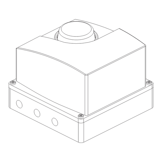
- Page 1 VALVE CONTROLLER ND800PA Rev. 1.0 Installation, Maintenance and Operating Instructions 7 ND 72 en 4/2001...
-
Page 2: Table Of Contents
10.3 Electrical connections....19 Mounting on Metso Automation actuators 10.4 Adjustment ......19 with VDI/VDE mounting face (S1) . -
Page 3: Introduction
Optional plate Technical specifications µ General α The ND800PA valve controller is suitable for rotary and slid- ing stem valves. Actuator connection In accordance with VDI/VDE 3845 standard (S1) or as an option compatibility with other NE-series (S2). To replace an existing NE/NP positioner,... - Page 4 Enclosure Approvals Temp. ≤ +75 °C (+67 °F): Material: Anodized aluminium alloy Protection class: IP65, NEMA 4 and 4X Cenelec EEx ia IIC T5/T6 (pending), Temp. ≤ +50 °C (+122 °F): Mechanical position indicator: on cover CSA Class I, Division 2, Groups A, B, C Pneumatics ports: 1/4 NPT and D (pending)
-
Page 5: Safety Precautions
Attach the bracket (1) to the ND800PA. Attach the bracket (1) to the actuator. The shaft (40) of If the ND800PA is supplied with valve and actuator the tubes are the ND800PA must fit into the draught piece (2) shown mounted and the ND800PA adjusted in accordance with the in Fig. -
Page 6: Mounting On Linear Actuators Withmetso Automation Or Iec 60534 Mounting Face
Mount the controller loosely onto the controller mounting Mounting on linear actuators withMetso bracket. Automation or IEC 60534 mounting face Adjust the controller mounting bracket and the controller See Sections 10.5, 10.6. so that the controller is at 90° to the centre line of the Connect an airset directly to the actuator and position the actuator and the controller feedback lever is horizontal actuator at its mid-stroke position (see serial plate for... -
Page 7: Piping Of Supply Air
Terminals CAUTION: Do not exceed the permitted supply pressure of the ND800PA! Table 1 provides the recommended tube sizes in accordance with actuator sizes. Tube sizes are the minimum values allowed. For supply air choose a tube one size bigger. Operating times can be tested by the PDM. - Page 8 DOUBLE-ACTING ACTUATOR 1. Self closing. Default setting: PFA = CLO ROT = cC ( lose valve to lockwise) A0 = % (acc. to valve type) cLo = 2 % 2. Self opening. Setting: PFA = OPE ROT = cC ( lose valve to lockwise) A0 = % (acc.
-
Page 9: User Interface
The keyboard and the display of the ND800PA are shown in Fig. the + and - keys. Accept a changed value with r key, which returns 8. - Page 10 = Analog output block output signal (%) & > 5 s PREVIOUS SETTING (FACTORY = 90˚) > 5 s > 5 s & KEYSTROKES = Escape < 1 s & & & & & & Fig. 10. Keyboard operations...
-
Page 11: Configuration
Chapter 6. The ND800PA stays in the selected operation mode during the Now the ND800PA will work with basic settings including 2 ± 0.5 % g and d settings. signal cutoff margins to secure full closing of the valve. -
Page 12: Control Valve Related Settings
Table 3. Dead angle as percentage Control valve related settings The basic factory settings of the ND800PA assume a positioner fail Valve series action to be closing the valve and a clockwise closing direction for Valve size the position sensor. The setpoint cut-off CLOSE is set to 2 ± 0.5 %... -
Page 13: Maintenance
When cLo appears on the display, press the r key and the current default value as a percentage (%) appears on the The maintenance requirements of the ND800PA valve controller display. The Metso Automation’ standard default value is depend on the service conditions, for instance, the quality of instrument air. -
Page 14: Spool Valve
Spool valve Circuit board pack Before removing the spool valve (4) the prestage (3) must be taken Disassembly off. (See Section 5.1) Loosen the M8 screw (66) and turn the position indica- tor (65) outwards from the feedback shaft. Disassembly Unplug all wire connectors from the circuit board (5) and Unscrew the M4 screws (99, 4 pcs.) and remove the spool the signal wires from the terminal block (35). -
Page 15: Position Sensor
PDM communication. See the instruc- Tighten the M3 screws. tions in the ND800PA User’s guide. Install a 0,1 mm (0.004 in) thick gauge strip between the sensor and the spiral. Press the sensor against the spiral, without using unnecessary force, and tighten the screws (116) evenly. -
Page 16: Error Messages
Table 4 lists the error messages shown on the LCD display and their by the PDM. The error message is displayed until the cause of error explanations. is eliminated and the ND800PA unit is cold-started, i.e. the fieldbus is momentarily disconnected. Cold-start can also be done using PDM. -
Page 17: Trouble Shooting
Section 4.3 and Fig. 7 the actuator did not move or was stuck during calibration ND800PA/actuator mounting is incorrect, see Figs. 4, 5, 15 and Sections 10.2-10.6 spool valve sticks prestage is defective PDM trouble shooting is explained in the ND800PA User’s Guide. -
Page 18: Nd800/K00 (With Limit Switches)
ND800/K00 (WITH LIMIT SWITCHES) 10.1.3 Technical specifications 10.1.3.1 ND800/K00 10.1 Introduction Microswitch type: OMRON D2VW-5 (05) 10.1.1 General description OMRON D2VW-01 (06) (gold plated contacts) ND800 can be equipped with limit switches. ND800/K00 has 2 microswitches. Protection class IP67 Limit switches are used for electrical position indication of the valves and other devices. -
Page 19: Installing Nd800/K00 On A Valve Controller
10.2 Installing ND800/K00 on a valve controller 10.5 Removal of the limit switch ND800/K00 for accessing the valve controller The limit switch can be installed on an existing valve controller. Before the protective cover (46) can be removed the limit switch must be detached. -
Page 20: Drawings And Parts Lists
DRAWINGS AND PARTS LISTS 11.1 Exploded view and parts list 103, 104, 105 102, 104, 105 Item Qty Description Recommended spare Item Qty Description Recommended spare Housing Spool valve body ** Cover Spool ** Prestage unit * Gasket Spool valve assembly * Screw Circuit board pack Spring **... -
Page 21: Mounting Parts For B1C/B1J 6-20 Actuators
11.2 Mounting parts for B1C/B1J 6-20 actuators Item Qty Description Item Qty Description Mounting bracket Mounting bracket Draught piece Washer Washer Screw Screw Screw Screw Screw Hexagon nut Coupling jacket Screw Screw 11.3 Mounting parts for B1C/B1J 25-50, B1C 502 and B1J322 actuators Item Qty Description Mounting bracket... -
Page 22: Mounting Parts For Quadra-Powr , St, Sp And Valv-Powr Actuators
® 11.4 Mounting parts for Quadra-Powr , ST, ® SP and Valv-Powr actuators Item Qty Description Mounting bracket Screw Screw Screw Screw Adapter plug (QP II 1/S- 6/S only) Adapter plate (QP II 2B/K thr. 6_/K) Coupling jacket Item Qty Description Mounting bracket Coupling half... -
Page 23: Mounting Parts For D/R Linear Actuators
11.5 Mounting parts for D/R linear actuators LEVER ARM IN MID-STROKE POSITION DISTANCE FROM THE CENTER OF FEEDBACK ARM TO THE CENTER OF ACTUATING PIN 3.57 2.87 2.50 1.00" UP TO 5.00" 1.61 STROKE @ 70° ROTATE 1.07 0.80 35° 0.71 3.50 60°... -
Page 24: Mounting Parts For Linear Actuators With Iec 60534 Mounting Face
11.6 Mounting parts for linear actuators with IEC 60534 mounting face... -
Page 25: Connections
11.7 Connections 11.7.1 Connection diagram for ND800/K05 and ND800/K06 LIMIT SWITCH (.../K06B) A = Open (LS2) VALVE CONTROLLER (ND800) K = Closed (LS1) PG13,5 ../K06B (with limit switch) Connection diagram shows limit switch when actuator is in intermediate position. Switch A (upper) is activated at the open limit of the travel and switch K (lower at the cloised limit. Micro switches OMRON D2VW-01, gold plated contacts Ambient temperature -40...+85 °C / -40...+185 °F... -
Page 26: Device Gland Receptacles
11.7.2 Device gland receptacles +Voltage, brown - Voltage, blue Shield, black ND84.../...P1 = male eurofast type WEIDMÜLLER 945565, PG13.5/M12 +Voltage, brown - Voltage, blue Shield, grey ND84.../...P2 = male minifast type TURCK RSFV48/13.5... -
Page 27: Dimensions
DIMENSIONS ND800/S1 1/4NPT 0.83 M6x12 F05-¯50(VDI/VDE3845) 0.16 (35.4) 0.90 (1.39) ND800/S2 47.5 0.98 1.87 ¯6 ¯0.23 5/16UNC/13 -/L=1/2NPT 1.02 1.18 -/I=M20x1.5 5.39 -/NJ=R1/2... -
Page 28: Nd800/K00
12.1 ND800/K00 (35.4) 1/4 NPT ND800/S1 M6 / 10 ø6 PG13.5 13.9 5/6 UNC / 13 ND800/S2 47.5 ø6 ND800A = 1/2 NPT M5 / 18 = M20x1.5 = R1/2... -
Page 29: Type Coding
Not appplicable with double acting actuators. gauge, scale bar/psi/kPa, basic material bras, nickel plated, housing Single action, linear motion, applicable to Metso Automation stainless steel, glycerine filled. Specified on the option sticker. Filter D/R series diaphragm actuator. Not applicable to attachment size 5 m. - Page 32 Metso Field Systems Inc. Europe, Levytie 6, P.O.Box 310, 00811 Helsinki, Finland. Tel.int +358 20 483 150. Fax int. +358 20 483 151 North America, 4300 Windfern, Houston, TX 77041, USA, Tel. int +1-832-590-5000, Fax. int. +1-832-590-5060 North America, 3100 Medlock Bridge Road, Suite 250, Norcross, GA 30071, USA Tel. int. + 1 770 446 7818 Fax int. + 1 770 242 8386 Latin America, Av.
Need help?
Do you have a question about the ND800PA and is the answer not in the manual?
Questions and answers