Table of Contents
Advertisement
Quick Links
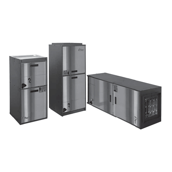
Tranquility Air Handler (TAH)
Table of Contents
3
4
4
5
6
7
8-13
14
15-16
17
Instal
Installation, Operation &
Mainte
Maintenance Instructions
Unit & System Checkout
Maintenance
Warranty
Revision History
Air Handler for
Tran
Tranquility Split Series
97B0101N01
Rev: 5/2/12
17
18
19
20
21-22
23
24
24
25
26
Advertisement
Table of Contents

Related Manuals for ClimateMaster TAH Series


Summary of Contents for ClimateMaster TAH Series
-
Page 1: Table Of Contents
Tranquility Air Handler (TAH) Air Handler for Tranquility Split Series Tran Installation, Operation & Instal Maintenance Instructions Mainte 97B0101N01 Rev: 5/2/12 Table of Contents Model Nomenclature Electrical Table General Information Wire Diagram Pre-Installation Blower Data Safety Electric Heat Installation Physical Data Electric Heat Wiring 21-22 Dimensional Data... - Page 2 Tranquility Air Handler (TAH) R e v. : M a y 2 , 2 0 1 2 This page was intentionally left blank. G e o t h e r m a l H e a t P u m p S y s t e m s...
-
Page 3: Model Nomenclature
Tranquility Air Handler (TAH) R e v. : M a y 2 , 2 0 1 2 Model Nomenclature 4 5 6 0 2 6 MODEL TYPE FUTURE USE T = TRANQUILITY R410A S = STANDARD CONFIGURATION CABINET SIZE AH = AIR HANDLER (WIDTH, INCHES) SIZE 026 ONLY;... -
Page 4: General Information
ClimateMaster Tranquility Air Handlers are designed for designed for installation above false ceiling or in a ceiling use with ClimateMaster indoor/outdoor split units and are plenum. Other unit confi gurations are typically installed available for vertical upfl ow or downfl ow, and horizontal left in a mechanical room. -
Page 5: Safety
Tranquility Air Handler (TAH) R e v. : M a y 2 , 2 0 1 2 Safety The installation of water source heat pump units and all CAUTION! associated components, parts and accessories which make up the installation shall be in accordance with the regulations CAUTION! It is recommended that an auxiliary of ALL authorities having jurisdiction and MUST conform to secondary drain pan be installed under units containing... -
Page 6: Physical Data
Tranquility Air Handler (TAH) R e v. : M a y 2 , 2 0 1 2 Unit Physical Data Model 026-A 026-B 038-B 038-C 049-B 049-C 064-C Emerson ECM Fan Motor & Blower Liquid I.D. Suction I.D. Fan Motor Type/Speeds ECM Variable Fan Motor (hp) Blower Wheel Size (Dia x W) -
Page 7: Dimensional Data
Tranquility Air Handler (TAH) R e v. : M a y 2 , 2 0 1 2 Unit Dimensional Data Detail A Scale 5/32 See Detail A R.A. Opening R.A. Opening 0.625 0.625 0.75 0.875 Overall Cabinet Cabinet Size Width Height Depth 18.5... -
Page 8: Installation
Tranquility Air Handler (TAH) R e v. : M a y 2 , 2 0 1 2 Installation The Tranquility Air Handlers are designed for upfl ow, horizon- using a suitable isolating material. tal, and downfl ow applications. The coils have a dry nitrogen 4. - Page 9 Tranquility Air Handler (TAH) R e v. : M a y 2 , 2 0 1 2 Installation Horizontal Left Installation Figure 1: Mounting Installation Options 1. For maximum effi ciency and customer ease of fi lter maintenance, it is recommended that a properly sized remote fi...
- Page 10 Tranquility Air Handler (TAH) R e v. : M a y 2 , 2 0 1 2 Installation Applications Tranquility Air Handlers can be applied in upfl ow, downfl ow, horizontal right and horizontal left applications without modifi cations. For horizontal applications, installation of an auxiliary/secondary drain pan is required.
- Page 11 Tranquility Air Handler (TAH) R e v. : M a y 2 , 2 0 1 2 Installation Figure 3: Air Coil Connection CAUTION! TXV (‘IN’ toward CAUTION! HFC-410A systems operate at higher Bulb (Must be compressor section) Equalizer pressures than R-22 systems. Be certain that service Installed and Line Insulated)
- Page 12 Tranquility Air Handler (TAH) R e v. : M a y 2 , 2 0 1 2 Installation Evacuation and Charging the Unit Figure 4: Condensate Drain Trap LEAK TESTING - The refrigeration line set must be pressurized and checked for leaks before evacuating and charging the unit. To pressurize the line set, attach refrigerant gauges to the service ports and add an inert gas (nitrogen or dry carbon dioxide) until pressure reaches 60-90 psig [413-620 kPa].
- Page 13 Tranquility Air Handler (TAH) R e v. : M a y 2 , 2 0 1 2 Installation Figure 5: Typical Split/Air Handler Installation Power Disconnects Insulated Low Voltage Linesets PVC Condensate with vented trap Compressor Section Air pad or Extruded polystryene...
-
Page 14: Electrical - Thermostat Wiring
Fault LED of 250 psig. This pressure switch can be ordered from Electric Heat ClimateMaster with a 1/4” internal fl are connection as part number 39B0005N02. Units with CXM board and ECM fan motor Units with CXM or DXM board and ECM fan motor... -
Page 15: Ecm Blower Control
Tranquility Air Handler (TAH) R e v. : M a y 2 , 2 0 1 2 ECM Blower Control The ECM fan is controlled by an interface board that TEST setting runs the ECM motor at 400 CFM/nominal ton at converts thermostat inputs and fi... - Page 16 Tranquility Air Handler (TAH) R e v. : M a y 2 , 2 0 1 2 ECM Blower Control Table b: ECM Board Tap Settings Cooling settings: TT, TS Units Heating settings: TT, TS Units Aux/Emerg Heat settings: TT, TS Units* Version I Version I Version I...
-
Page 17: Electrical - Power Wiring
Tranquility Air Handler (TAH) R e v. : M a y 2 , 2 0 1 2 Electrical - Power Wiring Figure 9: Remove Harness Plug WARNING! WARNING! Electrical shock hazard - Lock unit disconnect switch in open position before servicing unit. Failure to follow this warning could result in property damage, personal injury, or death. -
Page 18: Wire Diagram
Tranquility Air Handler (TAH) R e v. : M a y 2 , 2 0 1 2 Typical Wiring Diagram - 96B0143N01 G e o t h e r m a l H e a t P u m p S y s t e m s... -
Page 19: Blower Data
Tranquility Air Handler (TAH) R e v. : M a y 2 , 2 0 1 2 Blower Performance Data TAH Standard Unit Airfl ow in CFM with wet coil and clean air fi lter Cooling Mode Dehumid Mode Heating Mode Aux/ Model Motor... -
Page 20: Electric Heat Installation
Tranquility Air Handler (TAH) R e v. : M a y 2 , 2 0 1 2 Electric Heat Installation Overview Figure 11: Typical air handler installation The AG Series Auxiliary Electric Heat mounts internally in upfl ow (Figure 11) or downfl ow units and horizontal units. Horizontal units are rated for zero clearance at the unit and 1"... -
Page 21: Electric Heat Wiring
Tranquility Air Handler (TAH) R e v. : M a y 2 , 2 0 1 2 Electric Heat Wiring Figure 14: Power Wiring, Dual Circuits, 15 and 20kw Figure 15: Power Wiring, Single Circuit, 15, 20kw Wiring and Setup (all models) 1. - Page 22 Tranquility Air Handler (TAH) R e v. : M a y 2 , 2 0 1 2 Electric Heat Wiring Figure 18: Low Voltage Harness Connection Figure 19: Power Conduit And Wire Routing G e o t h e r m a l H e a t P u m p S y s t e m s...
-
Page 23: Electric Heat Staging Options
Tranquility Air Handler (TAH) R e v. : M a y 2 , 2 0 1 2 Electrical Heat Staging Options Table 1: AG Electric Heat Ratings Auxiliary TAH Models kW Rating Btuh Rating Minimum Electric 049- Heat 240V 208V 240V 208V Required...
Need help?
Do you have a question about the TAH Series and is the answer not in the manual?
Questions and answers