Advertisement
Quick Links
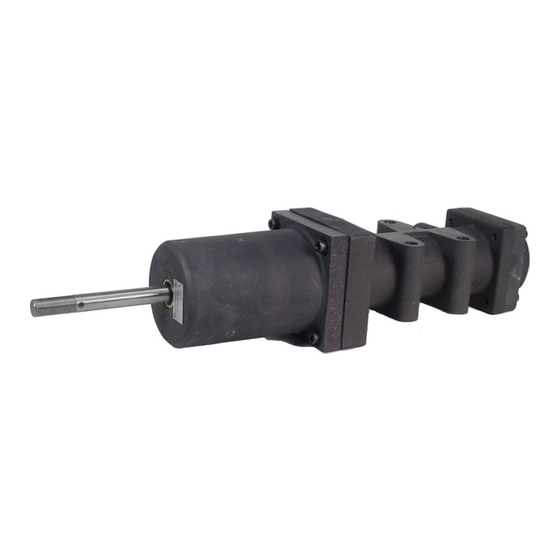
SIX R431006322 (P -063892-00001) AND SEVEN R431006321 (P -063981--00002)
The six and seven position cylinders are medium duty pneumatic
positioning devices that operate through six or seven predetermined
positions of ½" (12.7 mm) increments with total strokes of 2½" (63.5
mm) or 3" (76.2 mm) respectively. They were primarily designed for
power-shift transmissions but may also be utilized for indexing and
any other application where fixed stroke increments are required.
The ideal companion valve for these cylinders is Type "P" six or
seven position Rotair® Valve. An alternative control is an electro-
pneumatic switching circuit using 3-way solenoid valves.
cylinders are extremely rugged having anodized, corrosion resistant,
lightweight aluminum body, pistons and pistons stops.
WARNING: INSTALLATION AND
MOUNTING
The user of these devices must conform to all applicable electrical,
mechanical, piping and other codes in the installation, operation or
repair of these devices.
INSTALLATION! Do not attempt to install, operate or repair these
devices without proper training in the technique of working on
pneumatic or hydraulic systems and devices, unless under trained
supervision.
Compressed air and hydraulic systems contain high levels of stored
energy. Do not attempt to connect, disconnect or repair these
products when a system is under pressure. Always exhaust or drain
the pressure from a system before performing any service work.
Failure to do so can result in serious personal injury.
MOUNTING! Devices should be mounted and positioned in such a
manner that they cannot be accidentally operated.
INSTALLATION
Mount the cylinders in any desirable plane to a sturdy, flat surface
(preferably with the ports facing down) with three 3/8" bolts.
Mounting lugs are cast in the body of the cylinders. Avoid
misalignment with the load to be positioned since side thrust and
binding will affect the service life of the rod bearing and piston stop
seals.
All ports are 1/4"-18 NPT. The following ports should be piped
together with "T" connections: 3 with 3A on the six position cylinder,
3 with 3A and 6 with 6A on the seven position cylinder. Connections
should be made as close to the cylinder as possible to reduce the
number of lines from the control valve.
OPERATION
Maximum operating pressure is 150 psi (10 bar) within a
temperature range of -40° to 200°F (-40° to 93°C). The cylinder
piston rod reaches its various positions in response to pressure
being supplied to the cylinder ports as shown in the truth tables on
SM-1000.4905
POSITION CYLINDERS
Service Information
NOTE:
"P" Rotair Valve R431006324 (P -063984-00000) was designed to control
six position cylinder R431006322 (P-063982-00001) and valve R431006326
(P -063985-00000) was designed to control seven position cylinder
R431006321 (P -063981-00002). Both of these Rotair Valves have first
gear position adjacent to neutral and progress toward full automatic at the
extreme position of valve handle travel Rotair Valves can be made available
to have the handle position sequence identical to the transmission. Six
position Rotair R431006324 (P -063984-00000) should be connected as
follows:
Ports No. 1 and No. 5 plugged, Exhaust port is 1/8" NPT, pressure is
supplied to unnumbered port in the side of the pipe bracket, valve port No. 2
to cylinder port No. 2, valve No. 4 to cylinder No. 5, valve No. 3 to cylinder
No. 3 & 3a, and valve port No. 6 to cylinder port No. 6A in six position
cylinder R431006322 (P -063982-00001).
Seven position Rotair R431006326 (P -063985-00000) should be connected
as follows: port No. 1 plugged, exhaust port No. 4, pressure is supplied to
unnumbered port in the side of the pipe bracket, valve port No. 2 to cylinder
These
port No. 2, valve No. 5 to cylinder No. 5, valve No. 3 to cylinder No. 3 & No.
3A and valve port No. 6 to cylinder No. 6 & 6A in seven position cylinder
R431006321 (P -063981-00002).
pages 3 and 5. V means air must be vented to atmosphere, S
means air must be supplied and S/V means port can be supplied or
vented. whichever is most convenient in the control valve. Each
cylinder has reverse at full extended position of the rod and is spring
returned to neutral (next position in from reverse) from any position.
The transmissions which these cylinders usually control have the full
automatic or drive position adjacent to neutral. The corresponding
position is 5 on the seven position and 4 on the six position cylinder.
The sequential order of cylinder positions is a function of the "P"
Rotair Valve.
The forces developed by the cylinder are functions of the air
pressure applied to the exposed piston areas and are tabulated for
rod movement to the various stroke positions as shown on the
charts on pages 6 and 7.
The internal spring returns the piston rod to its Neutral position when
air pressure is intentionally or unintentionally exhausted from all
control lines. This safety feature returns the transmission to neutral
if the air supply is lost.
MAINTENANCE
Periodically disassemble the cylinder for cleaning and inspection.
Clean all metal parts with a nonflammable solvent and wash all
rubber parts with soap and water. Rinse thoroughly and dry, using
low pressure jet, if available. Replace all damaged or worn parts.
Reassemble the cylinder, lubricating each part as it is put in place.
Rubber parts should be lubricated with Dow Corning No. 55
pneumatic grease. Check the operation of the reassembled cylinder
by putting low pressure air in the ports in accordance with the truth
table, pages 3 and 5.
NOTE
:
the return springs are under compression.
ADJUSTMENT
AVENTICS six and seven positions require no adjustment.
When disassembling a cylinder, please use CAUTION as
Advertisement

Related Manuals for Aventics R431006322


Summary of Contents for Aventics R431006322
- Page 1 SIX R431006322 (P -063892-00001) AND SEVEN R431006321 (P -063981--00002) POSITION CYLINDERS Service Information NOTE: “P” Rotair Valve R431006324 (P -063984-00000) was designed to control six position cylinder R431006322 (P-063982-00001) and valve R431006326 (P -063985-00000) was designed to control seven position cylinder R431006321 (P -063981-00002).
-
Page 2: Exploded View
EXPLODED VIEW Six Position R431006322 (P –063982-00001 Page 2... - Page 3 SIX POSITION CYLINDER PARTS LIST M-4-N-1B CYLINDER P/N R431006322 (P -063982-00001) DWG. NO. CP63982A ITEM NO. QTY. DESCRIPTION NEW P/N OLD P/N SCREW, 1/4 X 20 X 3/4 CAP R431002203 P -049856-00046 PISTON 2 7/8 R431002303 P -064175-00000 O-RING, 2 3/4...
- Page 4 EXPLODED VIEW Seven Position R431006321 (P –063981-00002 Page 4...
-
Page 5: Assembly View
SEVEN POSITION CYLINDER PARTS LIST M5-N-1B P/N R431006321 (P -063981-00002) DWG. NO. CP63981A ITEM NO. QTY. DESCRIPTION NEW P/N OLD P/N R431006372 P -064186-0000 ROD, REAR PISTON R431006373 P -064188-0000 PISTON, 2 1/4 R431006376 P -064192-0000 O-RING, 2 1/4 O.D. See Kit See Kit O-RING, 5/8 O.D. - Page 6 SIX POSITION CYLINDER Page 6...
- Page 7 SEVEN POSITION CYLINDER Page 7...
- Page 8 No charge will be made for labor with respect to defects covered by this Warranty, provided that the work is done by AVENTICS or any of its authorized service facilities.
Need help?
Do you have a question about the R431006322 and is the answer not in the manual?
Questions and answers