
Related Manuals for Acqiris U5303A


Summary of Contents for Acqiris U5303A
- Page 1 Acqiris U5303A Acquisition Card 2 channels, 12-bit, 500 MS/s to 4 GS/s, DC up to 2 GHz bandwidth, with real-time processing User's Manual...
- Page 2 No part of this manual may be reproduced in any form or by any means (including electronic storage and retrieval or translation into a foreign language) without prior agreement and written consent from Acqiris SA as governed by international copyright laws. Version...
-
Page 3: Table Of Contents
U5303A Acquisition Card User's Manual U5303A Acquisition Card User's Manual This help document is intended to provide in-depth information and reference material specific to your ADC Card. For information about installation and about getting started with your ADC Card, please refer to the... - Page 4 ADC cards ? 11.4 Q. What happens if the host processor goes in hibernation mode? General information 12.1 Safety notes 12.2 Cleaning precautions 12.3 Product markings 12.4 Electrical & environmental specifications 12.5 Related documentation 12.6 Full product family U5303A User's Manual...
-
Page 5: Introduction
4 GB. The U5303A includes a Xilinx Virtex-6 FPGA allowing implementation of custom real-time processing algorithms. At the heart of the U5303A is a data processing unit (DPU) based on the Xilinx Virtex-6 FPGA. This DPU is responsible for controlling the module functionality, data flow and real-time signal processing. -
Page 6: Block Diagram
Block diagram Block diagram Figure 1.1 - U5303A block diagram Most of the technical specifications concerning your particular ADC card are covered in this manual, however for the complete specifications please refer to the U5303A datasheet. U5303A User's Manual... -
Page 7: Main Adc Card Features
Main ADC Card Features Chapter 1 Main ADC Card Features 1.1 U5303A front panel features 1.2 Channel input specifications 1.3 Sampling and Data Acquisition 1.4 Trigger 1.5 Calibration U5303A User's Manual... -
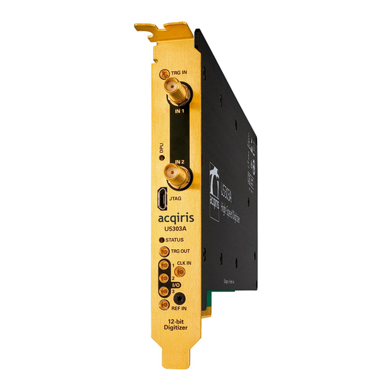
Page 8: U5303A Front Panel Features
MMCX female TTL compatible. External clock input. AC coupled and 50 Ω terminated, signal CLK IN MMCX female level: +5 to +15 dBm. Please refer to U5303A datasheet details. External reference clock input, AC coupled and 50 Ω ter- REF IN MMCX female minated. -
Page 9: Channel Input Specifications
- 1 GS/s (-SR1) - 1.6 GS/s (-SR2) - 2 GS/s (-SR3). For U5303A with INT option, the two channels may be combined to form an interleaved channel at: - 1 GS/s (-SR0) - 2 GS/s (-SR1) - 3.2 GS/s (-SR2) - 4 GS/s (-SR3). - Page 10 10-90 10-90real where T (ns)≈0.35/BW(GHz). Vertical resolution The U5303A ADC Card uses a 12-bit ADC giving 4096 levels of ~0.25 mV average width when using the 1 V FSR. U5303A User's Manual...
-
Page 11: Sampling And Data Acquisition
62). Combining channels (Interleaving -INT option) When ordered with -INT option, the U5303A ADC card supports the capability of combining the converters (and their memories) from two channels to analyze a single input channel. With this feature the maximum sampling rate and the maximum amount of acquisition memory are doubled. -
Page 12: Trigger
The different trigger modes are detailed in section Trigger modes and time-stamps (page 63) Trigger impedance & coupling The U5303A has a fixed 50 Ω termination impedance with DC coupling. Trigger input bandwidths The bandwidth depends on the trigger source. - Page 13 Trigger precision and resolution With -SR1 option, the U5303A trigger time interpolator offers a resolution of 7.75 ps (nominal) and a precision of 20.7 ps RMS (nominal) . With -SR2/-SR3 options, the trigger resolution is 6.25 ps (nominal) and the precision 15 ps RMS (nominal) .
-
Page 14: Calibration
1.5 Calibration 1.5 Calibration The U5303A is factory calibrated and shipped with a calibration certificate. The internal calibration refers to the adjustment of ADC card internal parameters, corresponding to user selected parameters and required before starting acquisition. Internal calibration The internal calibration (or self-calibration) measures and adjusts the internal timing, gain and offset parameters between the ADCs and against a precise reference. - Page 15 The measured performance is then compared to published datasheet specifications. For each factory calibration, Acqiris tests the performance corresponding to all datasheet specifications, for every installed option. If needed, the DUT is adjusted and re-qualified ; ensuring it is in line with full specifications.
-
Page 16: Real-Time Processing Options
To check which options and mode are present on your ADC card you can use the MD3 Software Front Panel from the: Windows Start Menu > Acqiris > MD3 > Acqiris MD3 SFP. Then use the menu Help > About. The field System Options gives the option list. -
Page 17: Digitizer Firmware (Dgt Option)
Waveforms are stored in successive memory records as they arrive. Each waveform requires its own individual trigger. Figure 2.2 - Acquisition sequence using a multi-records. It is possible to miss a trigger at high trigger rate, as illustrated with trigger 3. U5303A User's Manual... - Page 18 Thanks to fast trigger rearm, the U5303A achieves very low “dead time” between the records of a multi-record acquisition. The “dead time” is the period after the end of an event when the card cannot accept a new trigger event. The re-arm time is provided in the U5303A's U5303A datasheet.
- Page 19 The timebase range defines the time period over which data is being acquired. For example, the U5303A-M02-SR2 has a standard acquisition memory of 64 MS/ch and a maximum sampling rate of 1.6 GS/s (non-interleaved). Therefore, at the maximum sampling rate, the ADC card can record a signal over a time window of up to 41 ms (approx.
-
Page 20: Real-Time Averaging (Avg Option)
The time needed to perform the last accumulation AVG Dead Time, which depends on the number of samples acquired. The AVG Dead Time can be estimated at #Samples x 2.1 [ns] for SR2, or at #Samples x 1.77 [ns] for SR3. U5303A User's Manual... - Page 21 NoiseBase: Specifies the noise base value for the noise suppressed accumulation. The noise base is subtracted from data values which are higher than the configured threshold. This parameter is defined per channel in ADC counts. It can be configured in the range [0 to 8191]. U5303A User's Manual...
- Page 22 The NSA basenoise must be equal or smaller than NSA threshold. The U5303A uses an ADC with 12-bit of vertical resolution. To improve the baseline stability, the U5303A averager firmware provides a baseline stabilization processing which is optimum with 13- bit of vertical resolution.
- Page 23 2.4 Real-time averaging (AVG option) Figure 2.5 - Example of signal to noise ratio vs Number of averagers for U5303A. Parameters ActiveSource (IAqMD3Trigger.ActiveSource property): Specifies the trigger source. There are three trigger sources: internal, external and self-trigger. If the Self-Trigger mode is selected the Self-Trigger parameters should be set and the IO 3 output should be enabled.
- Page 24 Figure 2.7 - Comparison of the two modes of operation for baseline correction calculation The baseline correction computation is recommended when the number of pulses is not too high. U5303A User's Manual...
- Page 25 Output data format The U5303A uses an ADC with 12-bit of vertical resolution. To improve the baseline stability, the U5303A averager firmware provides a baseline stabilization processing which is optimum with 13-bit of vertical resolution. Therefore, the averager firmware provides raw data for each single accumulation in 13-bit.
- Page 26 DataInversionEnabled: the data acquired may be inverted if desired, before the averaging. Mode: select the averager mode (IAqMD3Acquisition.Mode property in IVI.NET or AQMD3_VAL_ ACQUISITION_MODE_AVERAGER in IVI-C) Enabling the Averager mode IVI.NET The average mode is selected by setting IAqMD3Acquisition.Mode property to Acqiris.AqMD3.AcquisitionMode.Averager: instrument.Acquisition.Mode = AcquisitionMode.Averager; IVI-C U5303A User's Manual...
- Page 27 Software. Detailed help on these interfaces may be found in the AqMD3 IVI Driver Help — Please refer to AqMD3.chm (IVI-C) or Acqiris.AqMD3.Fx40.chm (IVI.NET). Or the alternative drive letter where the Acqiris MD3 Software has been installed on your machine. U5303A User's Manual...
- Page 28 AqMD3_FetchAc- This waveform is from a previously initiated accu- cumulatedWaveformReal64 mulated acquisition in Averager or Peak Detection mode. Returned waveform data units are Volts. Configures the baseline correction properties. AqMD3_BaselineCorrectionConfigure U5303A User's Manual...
- Page 29 Defines the lower limit of the baseline range. Outside of this range, data AQMD3_ATTR_BASELINE_ values will be ignored. This is an absolute value (from 0 to vertical range). CORRECTION_ THRESHOLD_LOW The units are ADC counts. AQMD3_ATTR_BASELINE_ Applies a digital offset after the baseline correction. CORRECTION_DIGITAL_ OFFSET U5303A User's Manual...
- Page 30 2.4 Real-time averaging (AVG option) IVI.NET U5303A User's Manual...
- Page 31 The units are ADC counts. Specifies the threshold of the Noise Sup- pressed Accumulation. Each data value Threshold must exceed the threshold value to be entered into the sum. The units are ADC counts. U5303A User's Manual...
- Page 32 The units are ADC counts. Defines the lower limit of the baseline range. Outside of this range, data values will be ignored. ThresholdLow This is an absolute value (from 0 to vertical range). The units are ADC counts. U5303A User's Manual...
-
Page 33: Peak Detection (Pkd)
Using this algorithm, peaks can be found on-the-fly in signals with frequencies up to half the sample rate. Figure 2.8 - Peak detection algorithm Parameters(Channels.Item.PeakDetection interface): AmplitudeAccumulationEnabled: selects if the peak value is stored or the peak value is forced to '1'. U5303A User's Manual... - Page 34 -SR3 option: from 0 to 134.217728 ms (i.e. 2 x 8 x 10 seconds) -SR2 option: from 0 to 167.77216 ms (i.e. 2 x 10 x 10 seconds) -SR1 option: from 0 to 268.435456 ms (i.e. 2 x 16 x 10 seconds). U5303A User's Manual...
- Page 35 In addition to threshold options, this mode is a way to exclude unwanted signal values from the baseline calculation, assuming that there is no or very low active signal outside the acquisition window. U5303A User's Manual...
- Page 36 (no need for a new start). Out-AccumulationActive: ADC card output (IO 2). This signal informs that the ADC card is busy accumulating. Out-AcquisitionActive: ADC card output (IO 1 or IO 2). This signal informs that the ADC card is busy acquiring. U5303A User's Manual...
- Page 37 IVI-C Functions AqMD3_SelfTriggerAbortGeneration AqMD3_SelfTriggerInitiateGeneration AqMD3_SelfTriggerSquareWaveConfigure AqMD3_SelfTriggerCustomWaveLoadConfigurationFile AqMD3_BaselineCorrectionConfigure AqMD3_PeakDetectionConfigure Attributes AQMD3_ATTR_SELF_TRIGGER_MODE AQMD3_ATTR_SELF_TRIGGER_SQUARE_WAVE_DUTY_CYCLE AQMD3_ATTR_SELF_TRIGGER_SQUARE_WAVE_FREQUENCY AQMD3_ATTR_SELF_TRIGGER_SQUARE_WAVE_SLOPE AQMD3_ATTR_ACQUISITION_MODE AQMD3_ATTR_ACQUISITION_NUMBER_OF_AVERAGES AQMD3_ATTR_CHANNEL_DATA_INVERSION_ENABLED AQMD3_ATTR_BASELINE_CORRECTION_MODE AQMD3_ATTR_BASELINE_CORRECTION_THRESHOLD_HIGH AQMD3_ATTR_BASELINE_CORRECTION_THRESHOLD_LOW AQMD3_ATTR_BASELINE_CORRECTION_DIGITAL_OFFSET AQMD3_ATTR_PEAK_DETECTION_RISING_DELTA Or the alternative drive letter where the Acqiris MD3 Software has been installed on your machine. U5303A User's Manual...
- Page 38 InitiateGeneration IAqMD3TriggerSourceSelfTrigger Mode IAqMD3TriggerSourceSelfTriggerSquareWave Configure IAqMD3TriggerSourceSelfTriggerSquareWave DutyCycle IAqMD3TriggerSourceSelfTriggerSquareWave Frequency IAqMD3TriggerSourceSelfTriggerSquareWave Slope IAqMD3TriggerSourceSelfTriggerCustomWave LoadConfigurationFile IAqMD3Acquisition Mode IAqMD3Acquisition NumberOfAverages IAqMD3Channel DataInversionEnabled IAqMD3ChannelAccumulationBaselineCorrection Configure IAqMD3ChannelAccumulationBaselineCorrection DigitalOffset IAqMD3ChannelAccumulationBaselineCorrection Mode IAqMD3ChannelAccumulationBaselineCorrection ThresholdHigh IAqMD3ChannelAccumulationBaselineCorrection ThresholdLow IAqMD3ChannelPeakDetection Configure IAqMD3ChannelPeakDetection AmplitudeAccumulationEnabled IAqMD3ChannelPeakDetection FallingDelta IAqMD3ChannelPeakDetection RisingDelta U5303A User's Manual...
-
Page 39: Readout Modes
Multi-record mode: one shot with multiple waveforms, with multiple triggers Figure 3.1 - Acquisition sequence using a single record. Figure 3.2 - Acquisition sequence using multi-records. The specific readout mode(s) detailed in the following depends on your product version and ordered options. U5303A User's Manual... -
Page 40: Continuous Simultaneous Acquisition And Readout (Csr)
The data rate that can be sustained without overflow is limited by the PCIe sustained throughput on the target system. There is no gap in the acquisition. Figure 3.3 - Acquisition and readout sequence with CSR mode. U5303A User's Manual... - Page 41 The size of the channel represents the volume of data per seconds that can be extracted from the ADC card. When the stream data rate is larger than the available PCIe data rate, an overflow occurs. The following picture illustrates the above mentioned concept. U5303A User's Manual...
- Page 42 The maximum data rate that can be sustained without overflow is limited by the PCIe sustained throughput on the target system, i.e. it depends on user host processor and operating system settings. To have a list of recommended system and settings, please contact technical support support@acqiris.com. U5303A User's Manual...
- Page 43 IMSR/512. Notes: • StreamSamples can be “StreamCh1” or “StreamCh2”; the application can choose to read one or the other or both. • StreamMarkers can only be “StreamTriggers”; the application can choose to read it or not. U5303A User's Manual...
- Page 44 “StreamCh1”. • The driver guarantees that all samples fetched from a stream are contiguous (no gaps or missing samples). Acquisition sequence An example of CSR acquisition sequence is illustrated below. U5303A User's Manual...
- Page 45 3.2 Continuous Simultaneous acquisition and Readout (CSR) Figure 3.6 - CSR acquisition sequence. To optimize the application data throughput it is recommended to use NbOfElementsToFetch > 1 M, especially for application with high trigger rate. U5303A User's Manual...
- Page 46 This function returns a stream of Elements. The ElementSizeInBits and the meaning of each Ele- AqMD3_StreamFetchDataInt32 ment depend on the StreamType. Or the alternative drive letter where the Acqiris MD3 Software has been installed on your machine. U5303A User's Manual...
- Page 47 Specifies whether the Data Truncation is enabled. TRUNCATION_ENABLED Specifies whether the output stream Element contains the most sig- AQMD3_ATTR_STREAM_SAMPLES_DATA_ nificant or the least significant bits of the raw digitizer data sample. TRUNCATION_KEEP_MSB Ignored if DataTruncationEnabled is False. U5303A User's Manual...
- Page 48 DataTruncationEnabled Specifies whether the Data Truncation is enabled. Specifies whether the output stream Element contains the most sig- DataTruncationKeepMsb nificant or the least significant bits of the raw ADC card data sample. Ignored if DataTruncationEnabled is False. U5303A User's Manual...
-
Page 49: Triggered Simultaneous Acquisition And Readout (Tsr)
Each segment is triggered by an external or software trigger. Unlike Continuous Simultaneous acquisition and Readout (CSR) (page 40) mode, this mode allows gaps in the acquisition. Figure 3.7 - Sequence of a multi-record acquisition, with TSR mode. U5303A User's Manual... - Page 50 There is a compromise between memory readout frequency and PCIe delay. (Recommendation is to set the number of record before readout to reach around 1 MB of data). It is recommended to set the NumRecordsToAcquire to a value close to 1 MB/(Record size). U5303A User's Manual...
- Page 51 Detailed help may be found in the AqMD3 IVI Driver Help — Please refer to AqMD3.chm (IVI- C) or Acqiris.AqMD3.Fx40.chm (IVI.NET). IVI-C Functions AQMD3_TSRContinue Attributes AQMD3_ATTR_TSR_ENABLED AQMD3_ATTR_TSR_IS_ACQUISITION_COMPLETE Or the alternative drive letter where the Acqiris MD3 Software has been installed on your machine. U5303A User's Manual...
- Page 52 3.3 Triggered simultaneous acquisition and readout (TSR) AQMD3_ATTR_TSR_MEMORY_OVERFLOW_OCCURRED IVI.NET Interface Method / Property name IAqMD3AcquisitionTSR Continue IAqMD3AcquisitionTSR Enabled IAqMD3AcquisitionTSR IsAcquisitionComplete IAqMD3AcquisitionTSR MemoryOverflowOccurred U5303A User's Manual...
-
Page 53: Averager With Triggered Simultaneous Acquisition And Readout (Avg/Tsr/Int Option)
The readout can be performed as soon an "averager record" is acquired. Sequence in AVG and TSR mode Figure 3.9 - Acquisition and readout seuence in AVG+TSR mode. The feature Noise suppress accumulation (NSA) is not supported with AVG+TSR mode. U5303A User's Manual... - Page 54 Abort function is not yet supported in AVG +TSR mode. The workaround is to close and reinitialize the card. Usage Supported configuration U5303A-INT/AVG/TSR/SR1 + INT @ 2 GS/s Other sampling rate SR0, SR2, and SR3 are not supported. AVG&TSR mode is enabled only with interleaved mode. Not supported in dual channel mode...
- Page 55 3.4 Averager with triggered simultaneous acquisition and readout (AVG/TSR/INT option) Figure 3.10 - AVG+TSR acquisition sequence. U5303A User's Manual...
- Page 56 Detailed help may be found in the AqMD3 IVI Driver Help (AqMD3.chm). Code example Program examples can be found in here: For IVI-C :\Program Files\IVI Foundation\IVI\Drivers\AqMD3\Examples\IVI-C For IVI.NET C:\Program Files\IVI Foundation\IVI\Drivers\AqMD3\Examples\IVI.NET Or the alternative drive letter where the Acqiris MD3 Software has been installed on your machine. U5303A User's Manual...
-
Page 57: Other Signal Processing Features
This sections presents the on-board signal processing features that can be enable e.g. to optimize signal performance or reduce data volume, depending on each application. These features are common to the acquisition modes, excepted when specified differently. 4.1 Sampling rate reduction (binary decimation) 4.2 Custom firmware capability (FPGA Development Kit) U5303A User's Manual... -
Page 58: Sampling Rate Reduction (Binary Decimation)
Table 4.1 - List of selectable sampling rates. The accuracy of absolute trigger time is guaranteed (as specified in the U5303A datasheet) down to sample rates 1/16 of the highest sample rate (1/32 of the highest sample rate with interleaving). -
Page 59: Custom Firmware Capability (Fpga Development Kit)
4.2 Custom firmware capability (FPGA Development Kit) 4.2 Custom firmware capability (FPGA Development Kit) The -FDK (FPGA Development Kit) option allows the access to the on-board processing FPGA for custom algorithm implementation. For details, please contact technical support support@acqiris.com. U5303A User's Manual... -
Page 60: Application Options
– 400 MHz bandwidth (-F05) – 256 MB acquisition memory (-M02) – LX195T DPU FPGA The -SS2 and SS3 options are using a U5303A pre-configured version composed of: – 1 GS/s sampling rate (-SR1) – 650 MHz bandwidth (-F05) – 256 MB acquisition memory (-M02) –... -
Page 61: Control And Synchronization
Control and Synchronization Chapter 6 Control and Synchronization 6.1 External clock and reference 6.2 Trigger modes and time-stamps 6.3 Trigger output 6.4 Multi-purpose inputs and outputs U5303A User's Manual... -
Page 62: External Clock And Reference
The external reference is nominally at 100 MHz. However, frequencies in a range will be accepted. If your input is not at exactly the specified value, you must remember to compensate for the difference in your application since the ADC card and the driver have no way to know about such deviations. U5303A User's Manual... -
Page 63: Trigger Modes And Time-Stamps
TRG IN front panel input connector (external triggering) a software trigger (See How to generate a software trigger? (page 86)) Pre- and post-trigger delay Description To increase trigger flexibility, a pre- or post-trigger delay can be applied to the trigger position. U5303A User's Manual... - Page 64 Thus it is only natural that the software drivers treat pre- and post-trigger delays as a single parameter in seconds that can vary between: – NumberSamples * SamplingInterval (100% pre-trigger) and + MaxPostTrigSamples * SamplingInterval (max post-trigger). The ADC card hardware accepts pre- and post-trigger adjustments in increments of 16 samples. U5303A User's Manual...
- Page 65 Trigger Time Interpolator (TTI). This information is essential for determining the precise relation between the trigger and the digitized samples of the signal. The TTI resolution determines the resolution of the trigger time-stamps. Please refer to Trigger section of your U5303A datasheet for the relevant specifications.
- Page 66 TriggerTime is an absolute time and cannot be set to zero. If it is set to NotATime, the waveform is empty or there is no absolute reference for the waveform. U5303A User's Manual...
-
Page 67: Trigger Output
When using TriggerAccepted, there is no resynchronization. The pulse duration is typically 960 ±20 ns with SR0 option,480 ±16 ns with SR1 option, 300 ±10 ns with SR2 option, or 240 ±10 ns with SR3 option. U5303A User's Manual... - Page 68 For an ECL compatible signal, terminated on 50 Ω to –1.2 V, set the offset to –1.2 V and the output will be in the range [–0.8 to –1.6 V]). Alternatively, to reduce the current drawn from the ADC card, the terminations shown here can be used: U5303A User's Manual...
- Page 69 6.3 Trigger output Figure 6.3 - Suggested trigger signal terminations. The external trigger output functionality is implemented in the hardware. No trigger out signal occurs for software-generated triggers. U5303A User's Manual...
-
Page 70: Multi-Purpose Inputs And Outputs
Indicates that the accumulation is currently run- Requires - Out-AccumulationActive Level ning. AVG or - PKD option. IO 3 only. Requires - Out-AveragerAwg Self-Trigger output. AVG or - PKD option. Table 6.4 - List of signals selectable for the programmables I/Os . U5303A User's Manual... - Page 71 50 Ω resistor in series. Therefore the available output high level voltage will depend on the load applied. In the example below a 50 Ω termination will result in a nominal high level of 1.6 V. (Vo = (Rload/(50 + Rload)) * 3.3). Figure 6.5 - Output equivalent circuit. U5303A User's Manual...
-
Page 72: Programming Information
Visual C++/CLI, Visual Basic.NET Driver API documentation The AqMD3 APIdocumentation can also be accessed from: IVI-C: Start > Acqiris > MD3 > Documentation > AqMD3-C IVI Driver Version# Documentation IVI.NET: Start > Acqiris > MD3 > Documentation > AqMD3.NET IVI Driver Version# Documentation... -
Page 73: Programming With The Ivi-C Driver In Various Development Environments
For Library Files (x64) add: C:\Program Files (x86)\IVI Foundation\IVI\Lib_x64\msc Note: For 32 bit operating systems paths start with: C:\Program Files\ Alternately, these paths may be entered in the Project Properties dialog, Configuration Properties, C++ and Linker panes. U5303A User's Manual... - Page 74 IDs are #define'd constants listed in the AqMD3.h header file and documented in the "Attributes by Name" section of the help file. The following example demonstrates basic usage of attribute accessors to read and write IVI-C driver attribute values. U5303A User's Manual...
-
Page 75: Migrating From Md2 2.X To Md3
7.3 Migrating from MD2 2.x to MD3 3.x 7.3 Migrating from MD2 2.x to MD3 3.x Please refer to the following documents for guidelines, accessible from: Start > Acqiris > MD3 > Documentation or from: C:\Program Files\Acqiris\MD3\Documentation AgMD2 to AqMD3 (IVI-C) Software Migration Note.pdf AgMD2 IVI.COM to AqMD3 IVI.NET Software Migration Note.pdf... -
Page 76: Initial Configuration
Fixed (Sample clock external frequency / Samp- Sample clock external divider Depends on SRx option ling rate) Reference oscillator Internal Reference oscillator frequency 100 MHz Fixed Record size 1024 Number of records to acquire Number of averages for AVG and PKD mode only U5303A User's Manual... -
Page 77: Apply Setup
Does the equivalent of Reset and then, (1) disables class extension capability groups, (2) ResetWithDefaults sets attributes to initial values defined by class specs, and (3) configures the driver to option string settings used when Initialize was last executed. U5303A User's Manual... -
Page 78: How To
8.9 How to perform binary decimation? (depending on firmware) 8.10 How to perform partial readout? 8.11 How to load a new firmware? 8.12 How to switch from normal mode acquisition (Multi-record) to averager mode or peak detection mode? U5303A User's Manual... -
Page 79: How To Discover The Pxi Instrument
&& count>0 ) printf( "Found: \"%s\"\n", rsrc ); status = viFindNext( find, rsrc ); } while( status==VI_SUCCESS ); viClose( find ); else if( count==0 ) printf( "No PXI instrument found\n" ); viClose( rm ); return 0; U5303A User's Manual... -
Page 80: How To Calibrate The Card
Channel.CalibrationTargetVoltage. Note that when set to true, the Channel.Offset value is taken into account in the self-calibration, and therefore changing the Channel.CalibrationTargetVoltage value, or changing the Channel.Offset, will require a new self-calibration. U5303A User's Manual... - Page 81 (group B and C) has to be performed when starting a new session.Thus the Save and Load functions, only apply to Acquisition sampling rate and Channel parameters (group A). Only these parameters can be re-used between sessions. U5303A User's Manual...
- Page 82 If the clock mode (Reference Oscillator Source or Sample Clock Source) is changed, steps 3 and 4 have to be repeated. Driver interfaces and functions The interfaces/methods/properties (functions/attributes) listed below are provided by the Acqiris MD3 driver. Please refer to AqMD3.chm (IVI-C) or Acqiris.AqMD3.Fx40.chm (IVI.NET) for detailed help. IVI-C Functions AqMD3_SelfCalibrate...
- Page 83 8.2 How to calibrate the card? IVI.NET Interface Method / Property name IsRequired SelfCalibrate IAqMD3Calibration SaveToFile LoadFromFile U5303A User's Manual...
-
Page 84: How To Configure And Read Data On Two Channels
// driver will allocate the proper amount of memory during the fetch call. Ivi.Digitizer.IWaveformCollection<Int16> waveformsCh1 = null; Ivi.Digitizer.IWaveformCollection<Int16> waveformsCh2 = null; waveformsCh1 = driver.Channels["Channel1"].MultiRecordMeasurement.FetchMultiRecordWaveform (firstRecord, numRecords, offsetWithinRecord, numPointsPerRecord, waveformsCh1 //fetch the data on channel 2 waveformsCh2 = driver.Channels["Channel2"].MultiRecordMeasurement.FetchMultiRecordWaveform (firstRecord, numRecords, offsetWithinRecord, numPointsPerRecord, waveformsCh2 U5303A User's Manual... -
Page 85: How To Access Repeated Capabilities
8.4 How to access repeated capabilities? 8.4 How to access repeated capabilities? For U5303A, the AqMD3 driver supports the following repeated capabilities with pre-defined values detailed in following table. Repeated capability Available instance name Channel "Channel1", "Channel2" "Internal1", "Internal2", "External1", "Software", "Immediate", TriggerSource "SelfTrigger"... -
Page 86: How To Generate A Software Trigger
IAqMD3Trigger.SendSoftwareTrigger (IVI.NET) sends a single software trigger. SendSoftwareTrigger() must be called as many times as required. Multi-record acquisitions required a trigger per record. Accumulated records require a trigger per accumulation. SendSoftwareTrigger() needs to be called for each trigger event. U5303A User's Manual... -
Page 87: How To Perform Time-Interleaving Acquisitions
AqMD3_SetAttributeViReal64(session, "", AQMD3_ATTR_SAMPLE_RATE, 3.2e9); Channels time-interleaving (IVI.NET) driver.Channels[L"Channel1"].TimeInterleavedChannelList = "Channel2"; spDriver->Acquisition->SampleRate = 3.2e9; In order to disable interleaveaving, the following code can be used: Channels time-interleaving (IVI-C) AqMD3_SetAttributeViString(session, "Channel1", AQMD3_ATTR_TIME_INTERLEAVED_CHANNEL_LIST, ""); Channels time-interleaving (IVI.NET) driver.Channels[L"Channel1"].TimeInterleavedChannelList = ""; U5303A User's Manual... -
Page 88: How To Enable Or Bypass The Bandwidth Limiter
AqMD3_SetAttributeViBoolean(session, "Channel1", AQMD3_ATTR_INPUT_FILTER_BYPASS, VI_FALSE); Using the AqMD3 IVI.NET driver: driver.Channels[L"Channel1"].Filter.Bypass = false; Bypassing the filter The following commands allow to bypass the filter. Using the AqMD3 IVI-C driver: AqMD3_SetAttributeViBoolean(session, "Channel1", AQMD3_ATTR_INPUT_FILTER_BYPASS, VI_TRUE); Using the AqMD3 IVI.NET driver: driver.Channels[L"Channel1"].Filter.Bypass = true; U5303A User's Manual... -
Page 89: How To Set The External Trigger
AqMD3_SetAttributeViString(session, "", AQMD3_ATTR_ACTIVE_TRIGGER_SOURCE, "External1"); AqMD3_SetAttributeViReal64(session, "External1", AQMD3_ATTR_TRIGGER_LEVEL, level); IVI.NET: spDriver->Trigger->ActiveSource = "External"; IAqMD3TriggerSourcePtr spTrigSrc = spDriver->Trigger->Sources->Item[L"External1"]; spTrigSrc->Level = level; //in volts The different trigger sources are listed in the section How to access repeated capabilities? (page 85). U5303A User's Manual... -
Page 90: How To Perform Binary Decimation? (Depending On Firmware)
To use the binary decimation and set the sample rate to a lower value use the AQMD3_ATTR_ SAMPLE_RATE attribute. sampleRate = 200e6; status=AqMD3_SetAttributeViReal64(session,””, AQMD3_ATTR_SAMPLE_RATE,sampleRate); Using the AqMD3 IVI.NET driver: To use the binary decimation and set the sample rate to a lower value use the SampleRate property. sampleRate = 200e6; driver.Acquisition.SampleRate = sampleRate; U5303A User's Manual... -
Page 91: How To Perform Partial Readout
Example using AqMD3 IVI-C Reading Int16 data in two blocks of points/2 length each (with NUM_RECORDS =1) U5303A User's Manual... - Page 92 , offsetWithinRecord + numPointToRead , numPointToRead , arraySize , dataArray , &actualRecords , actualPoints , firstValidPoint , initialXOffset , initialXTimeSeconds , initialXTimeFraction , &xIncrement , &scaleFactor , &scaleOffset); if (status != VI_SUCCESS) { /*handle errors and warnings*/ } U5303A User's Manual...
- Page 93 = driver.Acquisition.CreateWaveformCollectionInt32(numRecordsToRead, numPointToRead); //To first the first numPointToRead data: waveforms = driver.Channels[channel].MultiRecordMeasurement.FetchMultiRecordWaveform (firstRecord, numRecordsToRead, offsetWithinRecord, numPointToRead, waveforms); //To first the last numPointToRead data using the same waveform object: waveforms = driver.Channels[channel].MultiRecordMeasurement.FetchMultiRecordWaveform (firstRecord, numRecordsToRead, offsetWithinRecord + numPointToRead, numPointToRead, waveforms); U5303A User's Manual...
-
Page 94: How To Load A New Firmware
8.11 How to load a new firmware? 8.11 How to load a new firmware? The on-board FPGAs (field-programmable gate arrays) contain processor logic needed to efficiently execute several crucial functions. They will be automatically programmed at startup before calibration. U5303A User's Manual... -
Page 95: How To Switch From Normal Mode Acquisition (Multi-Record) To Averager Mode Or Peak Detection Mode
If you attempt to set a configuration that is not valid, the driver returns an error and does not apply any changes. For instance, you can proceed using the following instructions: Set the NumRecordsToAcquire = 1 driver.Acquisition.NumRecordsToAcquire = 1; Then change the acquisition mode to averager driver.Acquisition.Mode = AcquisitionMode.Averager; U5303A User's Manual... -
Page 96: Software Utilities
AqMD3Verify checks the version of control FPGA firmware already loaded, and if necessary, proposes the user to update the firmware, automatically using the Firmware Update Utility (As shown in the window below : Accept the FPGA update answering "y"). U5303A User's Manual... - Page 97 9.1 ADC card Verification Utility (AqMD3Verify) When the version of control FPGA firmware is updated and successful, please power off your computer, restart it again for the update to take effect, and process AqMD3Verify tool as described in this section. U5303A User's Manual...
-
Page 98: Accessories
DC to 1 GHz Input impedance 50 Ω Attenuation 3 dB VSWR (DC to 1 GHz) < 1.25 Impulse discharge current (8/20 us pulse) 10 kA Install the Attenuator and Spark Gap as shown in the diagram below. U5303A User's Manual... - Page 99 Both the Spark Gap and the Attenuator MUST be used together in order to fully protect the modules. In order to limit the input current, the Attenuator MUST be inserted between the Spark Gap and the input of the module. U5303A User's Manual...
-
Page 100: Faq
—————————————————————— 11.2 Q. How to manage the internal temperature? A. The operating temperature of the U5303A as specified in the U5303A datasheet, is the workstation internal ambient temperature at intake of the ADC card's fan. U5303A User's Manual... -
Page 101: What Are The Differences Between The Various Data Streaming Firmware Options Supported By High-Speed Adc Cards
11.3 Q. What are the differences between the various data streaming firmware options supported by high-speed ADC cards ? A. Acqiris ADC cards offer various acquisition modes depending on user requirements. Definitions DGT: standard DiGiTizer mode. TSR: Triggered Simultaneous acquisition and Readout. -
Page 102: What Happens If The Host Processor Goes In Hibernation Mode
ADC card, and re-initialize it when it wakes up from hibernation. After being powered off, the ADC card must reload of the FPGA (several seconds) upon power on, and a self-calibration is required. U5303A User's Manual... -
Page 103: General Information
Operators of this product must be protected from electric shock at all times. The responsible body must ensure that operators are prevented access and/or insulated from every connection point. In some cases, connections must be exposed to potential human contact. Product operators in these U5303A User's Manual... - Page 104 Cards and accessories shall not be connected to humans. Before performing any maintenance, disconnect the line cord and all test cables. Any part or component replacement must be done by Acqiris. No operator serviceable parts inside. Refer servicing to qualified personnel. To prevent electrical shock do not remove covers.
-
Page 105: Cleaning Precautions
는 이 점을 주 의하시기 바라 며 , 가정외의 지역에서 사용하는 것을 목적으 로 합니다 . This symbol on an card means caution, risk of danger. You should refer to the operating instructions located in the user documentation in all cases where the symbol is marked on the card. U5303A User's Manual... -
Page 106: Electrical & Environmental Specifications
12.5 Related documentation All documentation relating to your ADC card may be found from https://extranet.acqiris.com/. If you have run the Acqiris MD3 software installer on your PC, the related product documentation has been installed to your hard drive. U5303A User's Manual... -
Page 107: Full Product Family
PCIe Gen 2.0 and a x8 slot. PXI express ADC card This product line is composed of Acqiris PXI Express high-speed ADC cards. These are PXI Express compliant, using either a PXIe or PXIe Hybrid slot. Designed to benefit from fast data interfaces, the products can be integrated with other test and automation modules in PXIe and Hybrid chassis slots. - Page 108 This information is subject to change without notice. © Acqiris SA 2017 - 2019 Wednesday, July 10, 2019, Switzerland www.acqiris.com...
Need help?
Do you have a question about the U5303A and is the answer not in the manual?
Questions and answers