
Related Manuals for Acqiris U5309A


Summary of Contents for Acqiris U5309A
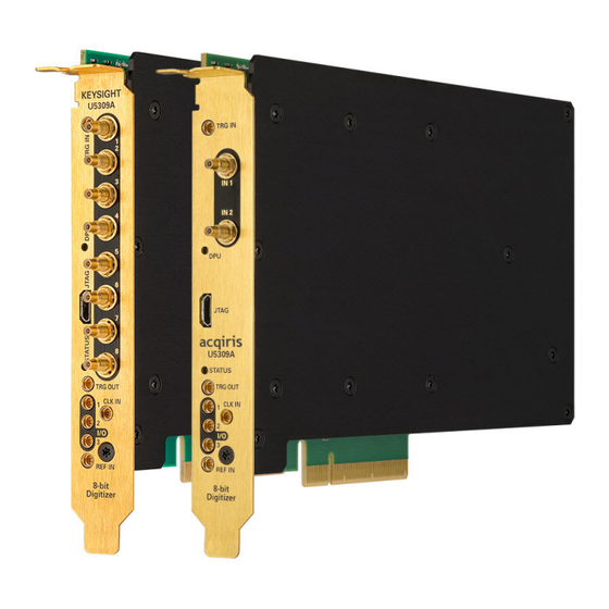
- Page 1 Acqiris U5309A Acquisition Card 2 or 8 channels, 8-bit, 500 MS/s to 2 GS/s, DC to 500 GHz bandwidth, with real-time processing User's Manual...
- Page 2 No part of this manual may be reproduced in any form or by any means (including electronic storage and retrieval or translation into a foreign language) without prior agreement and written consent from Acqiris SA as governed by international copyright laws.
-
Page 3: Table Of Contents
This help document is intended to provide in-depth information and reference material specific to your ADC Card product. For information on getting started with your ADC Card, please refer to the Startup Guide which can be downloaded from www.acqiris.com or which is installed with your software. General information... -
Page 4: Introduction
Benefiting from the very high data transfer rates of the PCIe 2.0 eight-lane interface, and occupying a single slot in a host PC, the U5309A offers high performance in a small footprint, making it an ideal platform for many commercial, industrial and aerospace & defense embedded systems. - Page 5 Key Features U5309A -CH2 block diagram U5309A -CH8 block diagram Most of the technical specifications concerning your particular ADC card are covered in this manual, however for the complete specifications please refer to the product's datasheet from www.acqiris.com. U5309A User's Manual...
-
Page 6: U5309A Front Panel Features
A 1 m SSMC to SMA cable is available as an accessory (U1092A-CB3) A 1 m SSMC to BNC cable is also available (U5300A-100). For the 2 channels version (U5309A-CH2 option) For the 8 channels version (U5309A-CH8 option) For cards delivered after April 2015. The driver automatically adjusts offset accordingly. -
Page 7: Channel Input Specifications
Channel Input Specifications Channel Input Specifications This section provides information and specifications regarding the input characteristics of the ADC card. Channel Input The U5309A offer several options for the number of channel input. Model Input channel(s) U5309A-CH1 1 channel available (IN 1) - Page 8 In general a pulse with a given 10-90% rise time T will be observed with a lower value given by: 10-90real 10-90 10-90real where T (ns)≈0.35/BW(GHz) Vertical Resolution The U5309A ADC Card uses a 8-bit ADC giving 256 levels at each input full scale range. U5309A User's Manual...
-
Page 9: Data Acquisition
Data Acquisition The sections below summarize the data acquisition characteristics. Sampling Rate The U5309A Acquisition card contains an analog-to-digital conversion (ADC) system that can sample waveforms, in a real time sampling mode, at rates shown in the table below. Channel Con- Max. - Page 10 LIDAR, Time-of-Flight, Ultrasonics, Medical and Biomedical Research, etc.). In multi-record acquisition mode the acquisition memory is divided into a pre-selected number of records. Waveforms are stored in successive memory records as they arrive. Each waveform requires its own individual trigger. U5309A User's Manual...
- Page 11 A very fast trigger rearm time is a crucial feature for multi-record acquisitions. Thanks to fast trigger rearm U5309A achieves very low “dead time” between the records of a multi-record acquisition. The “dead time” is the period after the end of an event when the card cannot digitize data for a new trigger event.
- Page 12 Above this «limit », the driver returns a PostTrigger overflow. This limitation is given by the table below, where acquisition time = record size x sampling interval + post- trigger delay. Max acquisition time (in Sample rate seconds) 1.00E+09 68.72 U5309A User's Manual...
-
Page 13: Trigger
ADC card will trigger on signals with a peak-to-peak amplitude > 0.5 V. The internal channel trigger of the U5309A, is implemented digitally and as such, the level may be configured via the driver, within the limits shown in the table below. "offset" and "range" refer to the channel's current Vertical Offset and Vertical Range settings. - Page 14 U5309A. Trigger precision and resolution The U5309A trigger time interpolator offers a resolution of 8 ps (nominal) and a precision of 15 ps RMS (nominal) . The channel trigger resolution and precision are both equal to 1 sample.
- Page 15 0 to (2 – 1) * block_size (samples) where block_size is 16 . Pre- or post-trigger delays are just different aspects of the same trigger positioning parameter: U5309A User's Manual...
- Page 16 Thus it is only natural that the software drivers treat pre- and post-trigger delays as a single parameter in seconds that can vary between: – NbrSamples * SamplingInterval (100% pre-trigger) and +maxPostTrigSamples * SamplingInterval (max post-trigger). You can refer to section How to set the external trigger? (page 66) for additionnal infomation. U5309A User's Manual...
-
Page 17: External Clock And Reference
ADC card and the driver have no way to know about such deviations. The input is 50 Ω terminated and AC coupled. Parameter Value Tolerance Nominal Frequency 100 MHz ±100 kHz U5309A User's Manual... - Page 18 External Reference (REF IN) Parameter Value Tolerance Signal level -3 dBm to +3 dBm Impedance 50 Ω Coupling If synchronization between several ADC cards is required, the reference signal should be applied to all of them. U5309A User's Manual...
-
Page 19: Calibration
Calibration Calibration The U5309A is factory calibrated ans shipped with a calibration certificate. The internal calibration refers to the adjustment of ADC card internal parameters, corresponding to user selected parameters and required before starting acquisition. Internal Calibration The internal calibration (or self-calibration) measures and adjusts the internal timing, gain and offset parameters between the ADCs and against a precise reference. - Page 20 If not, the required calibration is performed, and another production test is done to provide the cer- tificate of calibration. If repair is required, and the card is out of warranty, a repair quote will be provided. For more information, or to request for a calibration, please contact technical support support@acqiris.com. U5309A User's Manual...
-
Page 21: Trigger Output
The trigger output can be selected using following property / attribute: Driver Attribute / Property Available Instance Value IVI-C AQMD3_ATTR_TRIGGER_OUTPUT_ Boolean ENABLED AQMD3_ATTR_TRIGGER_OUTPUT_ Real64 OFFSET AQMD3_ATTR_TRIGGER_OUTPUT_ LowLevel SOURCE HighLevel TriggerAccepted TriggerAcceptedResync IVI.NET IAqMD3TriggerOutput.Source TriggerCompare IAqMD3TriggerOutput.Enabled Boolean IAqMD3TriggerOutput.Offset Double U5309A User's Manual... - Page 22 Alternatively, to reduce the current drawn from the ADC card, the terminations shown here can be used: Suggested trigger signal terminations. The External Trigger Output functionality is implemented in the hardware. No Trigger Out signal occurs for software-generated or digital triggers. U5309A User's Manual...
-
Page 23: Multi-Purpose Inputs And Outputs
The list of Available signals is indicated (as a comma separated list) by member IAqMD3ControlIO.AvailableSignals (IVI.NET) or attribute AQMD3_ATTR_CONTROL_IO_ AVAILABLE_SIGNALS (IVI-C). Signal Logic Levels The multi-purpose IO signals are 3.3 V CMOS compatible (5V Tolerant buffer). The levels shown in the table below should be observed. U5309A User's Manual... - Page 24 50 Ω resistor in series. Therefore the available output high level voltage will depend on the load applied. In the example below a 50 Ω termination will result in a nominal high level of 1.6 V. (Vo = (Rload/(50 + Rload)) * 3.3). Output equivalent circuit. U5309A User's Manual...
-
Page 25: Signal Processing Options
Self-Trigger mode for minimal synchronous (pattern) noise. Noise Suppressed Accumulation (NSA) In some applications, such as time-of-flight spectroscopy, the signal is a rare event sitting on top of a noisy baseline and the averaging process reduces the random noise. U5309A User's Manual... - Page 26 [0 to 255] . The NSA Base Noise must be equal or smaller than NSA Threshold. Timing sequence The minimum time between summed events depends on the trigger Rearm Time as specified in the Data sheet. U5309A User's Manual...
- Page 27 Figure below shows the signal to noise ratio using an external trigger at a frequency multiple of the sampling frequency (worst case) and the Self-Trigger at any frequency (best case), on a U5303A -Similar SNR improvement is expected on a U5309A starting from minimum SNR. U5309A User's Manual...
- Page 28 How to optimize NSA settings? (page 69). Multi-Purpose Inputs and Outputs (IO 1, 2) The multi-purpose inputs and outputs (IO 1, 2) in the front panel may be used to control the accumulation or read the ADC card status: U5309A User's Manual...
- Page 29 - If the number of acquired triggers is between 8 and 16, the data accumulation for the first 8 triggers can be read. - If the number of acquired triggers is between 16 and 24, the data accumulation for the first 16 triggers can be read. U5309A User's Manual...
- Page 30 Stops the generation of the self-trigger signal previously initiated. InitiateGeneration Starts the generation of the self-trigger signal. Mode Defines the self-trigger signal generation mode. Or the alternative drive letter where the Acqiris MD3 Software has been installed on your machine. U5309A User's Manual...
- Page 31 The units are ADC counts. Threshold Specifies the threshold of the Noise Sup- pressed Accumulation. Each data value must exceed the threshold value to be U5309A User's Manual...
- Page 32 Slope property (e.g. if Slope is set to positive DutyCycle defines the percentage that the square wave is in the high state). Units are percentage of the period. AQMD3_ATTR_SELF_TRIGGER_ Specifies the frequency of the self-trigger square wave signal. The U5309A User's Manual...
- Page 33 The units are ADC counts. AQMD3_ATTR_NSA_THRESHOLD Specifies the threshold of the Noise Suppressed Accumulation. Each data value must exceed the threshold value to be entered into the sum. The units are ADC counts. U5309A User's Manual...
- Page 34 FallingDelta: defines the amount by which two consecutive samples must differ to be considered as falling edge in the peak detection algorithm. Timing sequence The minimum time between summed events depends on the trigger Rearm Time as specified in the U5309A Datasheet. U5309A User's Manual...
- Page 35 Figure below shows the signal to noise ratio using an external trigger at a frequency multiple of the sampling frequency (worst case) and the Self-Trigger at any frequency (best case), on a U5303A -Similar SNR improvement is expected on a U5309A starting from minimum SNR. U5309A User's Manual...
- Page 36 How to optimize NSA settings? (page 69). Multi-Purpose Inputs and Outputs (IO 1, 2) The multi-purpose inputs and outputs (IO 1, 2) in the front panel may be used to control the accumulation or read the ADC card status: U5309A User's Manual...
- Page 37 Mode IAqMD3TriggerSourceSelfTriggerSquareWave Configure IAqMD3TriggerSourceSelfTriggerSquareWave DutyCycle IAqMD3TriggerSourceSelfTriggerSquareWave Frequency IAqMD3TriggerSourceSelfTriggerSquareWave Slope IAqMD3TriggerSourceSelfTriggerCustomWave LoadConfigurationFile IAqMD3Acquisition Mode IAqMD3Acquisition NumberOfAverages IAqMD3Channel DataInversionEnabled IAqMD3ChannelPeakDetection Configure IAqMD3ChannelPeakDetection AmplitudeAccumulationEnabled Or the alternative drive letter where the Acqiris MD3 Software has been installed on your machine. U5309A User's Manual...
- Page 38 PKD Configuration Interface Method / Property name IAqMD3ChannelPeakDetection FallingDelta IAqMD3ChannelPeakDetection RisingDelta IVI-C Functions AqMD3_SelfTriggerAbortGeneration AqMD3_SelfTriggerInitiateGeneration AqMD3_SelfTriggerSquareWaveConfigure AqMD3_SelfTriggerCustomWaveLoadConfigurationFile AqMD3_PeakDetectionConfigure Attributes AQMD3_ATTR_SELF_TRIGGER_MODE AQMD3_ATTR_SELF_TRIGGER_SQUARE_WAVE_DUTY_CYCLE AQMD3_ATTR_SELF_TRIGGER_SQUARE_WAVE_FREQUENCY AQMD3_ATTR_SELF_TRIGGER_SQUARE_WAVE_SLOPE AQMD3_ATTR_ACQUISITION_MODE AQMD3_ATTR_ACQUISITION_NUMBER_OF_AVERAGES AQMD3_ATTR_CHANNEL_DATA_INVERSION_ENABLED AQMD3_ATTR_PEAK_DETECTION_RISING_DELTA AQMD3_ATTR_PEAK_DETECTION_FALLING_DELTA AQMD3_ATTR_PEAK_DETECTION_AMPLITUDE_ACCUMULATION_ENABLED U5309A User's Manual...
- Page 39 In a Triggered Simultaneous Acquisition and Readout, the readout of the data is performed during the acquisition. The readout can be performed as soon as a programmable number of records is acquired. Each segment is triggered by an external or software trigger. Unlike CSR mode, this mode allows gaps in the acquisition. U5309A User's Manual...
- Page 40 Access (DMA) optimize the DMA transfer. There is a compromise between memory readout frequency and PCIe delay.(Recommendation is to set the number of record before readout to reach around 1 MB of data). It is recommended to set the NumRecordsToAcquire to a value close to 1 MB/(Record size). U5309A User's Manual...
- Page 41 Detailed help may be found in the AqMD3 IVI Driver Help ( P lease refer to AqMD3.chm (IVI-C) or Acqiris.AqMD3.Fx40.chm (IVI.NET) ). IVI.NET Interface Method / Property name IAqMD3AcquisitionTSR Continue IAqMD3AcquisitionTSR Enabled IAqMD3AcquisitionTSR IsAcquisitionComplete IAqMD3AcquisitionTSR MemoryOverflowOccurred Or the alternative drive letter where the Acqiris MD3 Software has been installed on your machine. U5309A User's Manual...
- Page 42 TSR Configuration IVI-C Functions AQMD3_TSRContinue Attributes AQMD3_ATTR_TSR_ENABLED AQMD3_ATTR_TSR_IS_ACQUISITION_COMPLETE AQMD3_ATTR_TSR_MEMORY_OVERFLOW_OCCURRED U5309A User's Manual...
- Page 43 When compared with standard averager mode, the AVG&TSR mode has neither AVG dead time nor readout time between acquisition sequences. The overall time dead between average records is minimum and limited to trigger re-arm time ~ 800 ns, minimizing the risk of trigger loss. U5309A User's Manual...
- Page 44 SR0 @ 500 MS/s SR1 @ 1 GS/s SR2 @ 2 GS/s U5309A-CH4 and U5309A-CH8 are not supported. Acquisition sequence First, user should configure the averager: Accumulation settings/features same as standard AVG. Then TSR mode has to be enabled. Acquisition are performed continuously until you stop them. See detailed acquisition sequence below.
- Page 45 Functional Description U5309A User's Manual...
- Page 46 Code example Program examples can be found in here: For IVI-C C:\Program FilesC \IVI Foundation\IVI\Drivers\AqMD3\Examples\IVI-C For IVI.NET C:\Program Files \IVI Foundation\IVI\Drivers\AqMD3\Examples\IVI.NET Or the alternative drive letter where the Acqiris MD3 Software has been installed on your machine. U5309A User's Manual...
- Page 47 Continuous Simultaneous acquisition and readout with Trigger (CST) Purpose The U5309A CST option answers customer need for simultaneous ADC card acquisition and readout with triggered acquisitions. Compared with standard acquisition mode, this mode enables longer acquisition duration, and is dedicated to applications requiring no trigger loss.
- Page 48 Using raw data output, trigger position is known with the accuracy of a sample (corresponding to the 1st sample). If customer application requires trigger position at sub-sample, the information is available on the marker stream (absolute trigger position). Acquisition sequence An example of CST acquisition sequence is illustrated below. U5309A User's Manual...
- Page 49 Usage U5309A User's Manual...
- Page 50 This mode supports an unlimited number of triggered records, depending of record size and trigger rate. Or the alternative drive letter where the Acqiris MD3 Software has been installed on your machine. U5309A User's Manual...
- Page 51 Triggered for CST enabled instruments. AQMD3_VAL_STREAMING_MODE_DISABLED Streaming Disabled (Default). AQMD3_VAL_STREAMING_MODE_TRIGGERED Triggered Streaming, for CST enabled instruments. This streaming mode performs continuous acquisitions of successive records and data readout, simultaneously. All records have the same pre- U5309A User's Manual...
- Page 52 Returns the number of bits per sample. SAMPLE AQMD3_ATTR_STREAM_SAMPLES_DATA_ Specifies whether the Data Emulation is enabled. If True, the output EMULATION_ENABLED data are fetched from an internal ramp waveform generator. If False, the output data are fetched from the digitizer ADC stream. U5309A User's Manual...
-
Page 53: Programming Information
Programming Information Programming Information This section provides general programming advice and specific information regarding the use of the Acqiris drivers. The AqMD3 IVI driver provides access to the functionality of AqMD3 ADC cards through a .NET or ANSI C API which also complies with the IVI specifications. - Page 54 5. For certain attributes and enum values you will need to refer to the tables below to find an equivalent. Exception Tables for AgMD2/AqMD3 IVI-C Signatures Please refer to AgMD2 to AqMD3 Software Migration Note.pdf installed with AqMD3. U5309A User's Manual...
- Page 55 Depends on SRx option Fixed (Sample clock external frequency / Sampling rate) Reference oscillator Internal Reference oscillator frequency 100 MHz Fixed Record size 1024 Number of records to acquire Number of averages for AVG and PKD mode only U5309A User's Manual...
- Page 56 Does the equivalent of Reset and then, (1) disables class extension capability groups, (2) sets attrib- utes to initial values defined by class specs, and (3) configures the driver to option string settings used when Initialize was last executed. U5309A User's Manual...
- Page 57 How to perform time-interleaving acquisitions? How to set the external trigger? How to perform binary decimation? (depending on firmware) How to load a new firmware? How to optimize NSA settings? How to switch from normal mode acquisition (Multi-record) to averager mode? U5309A User's Manual...
- Page 58 && count>0 ) printf( "Found: \"%s\"\n", rsrc ); status = viFindNext( find, rsrc ); } while( status==VI_SUCCESS ); viClose( find ); else if( count==0 ) printf( "No PXI instrument found\n" ); viClose( rm ); return 0; U5309A User's Manual...
- Page 59 Only the 1st time Clock mode External clock frequency Each time this parameter changes Clock source Each time this parameter changes Reference mode (External Each time this parameter changes or Internal Reference) The channel parameters are calibrated independently per channel. U5309A User's Manual...
- Page 60 The interfaces/methods/properties (functions/attributes) listed below are provided by the Acqiris MD3 driver. Detailed help may be found in the Please refer to AqMD3.chm (IVI-C) or Acqiris.AqMD3.Fx40.chm (IVI.NET) from Start > All programs > Acqiris MD3 ADC card > AqMD3 IVI Driver Help. U5309A User's Manual...
- Page 61 How to calibrate the instrument? IVI.NET Interface Method / Property name IAqMD3Calibration IsRequired SelfCalibrate SaveToFile LoadFromFile IVI-C Functions AqMD3_SelfCalibrate AqMD3_CalibrationLoadFromFile AqMD3_CalibrationSaveToFile Attributes AQMD3_ATTR_CALIBRATION_IS_REQUIRED U5309A User's Manual...
- Page 62 // the fetch call. Ivi.Digitizer.IWaveformCollection<Int16> waveformsCh1 = null; Ivi.Digitizer.IWaveformCollection<Int16> waveformsCh2 = null; waveformsCh1 = driver.Channels ["Channel1"].MultiRecordMeasurement.FetchMultiRecordWaveform(firstRecord, numRecords, offsetWithinRecord, numPointsPerRecord, waveformsCh1 //fetch the data on channel 2 waveformsCh2 = driver.Channels ["Channel2"].MultiRecordMeasurement.FetchMultiRecordWaveform(firstRecord, numRecords, offsetWithinRecord, numPointsPerRecord, waveformsCh2 U5309A User's Manual...
- Page 63 How to access repeated capabilities ? How to access repeated capabilities ? For U5309A, the AqMD3 driver supports the following repeated capabilities with pre-defined values detailed in following table. Repeated capability Available instance name Channel "Channeli", with i = [1-2] or = [1-8] depending on -CH2 or -CH8 option.
- Page 64 How to generate a software trigger? How to generate a software trigger? A call to function AqMD3_SendSoftwareTrigger (IVI-C) or to method IAqMD3Trigger.SendSoftwareTrigger (IVI.NET) sends a single software trigger. They need to be called as many times as they are incomplete records. U5309A User's Manual...
- Page 65 Channels time-interleaving (IVI-C) AqMD3_SetAttributeViString(session, "Channel1", AQMD3_ATTR_TIME_ INTERLEAVED_CHANNEL_LIST, "Channel2"); AqMD3_SetAttributeViReal64(session, "", AQMD3_ATTR_SAMPLE_RATE, e9); In order to disable interleaveaving, the following code can be used: Channels time-interleaving (IVI.NET) driver.Channels[L"Channel1"].TimeInterleavedChannelList = ""; Channels time-interleaving (IVI-C) AqMD3_SetAttributeViString(session, "Channel1", AQMD3_ATTR_TIME_ INTERLEAVED_CHANNEL_LIST, ""); U5309A User's Manual...
- Page 66 AqMD3_SetAttributeViString(session, "", AQMD3_ATTR_ACTIVE_TRIGGER_SOURCE, "External1"); AqMD3_SetAttributeViReal64(session, "External1", AQMD3_ATTR_TRIGGER_LEVEL, level); IVI.NET: spDriver->Trigger->ActiveSource = "External"; IAqMD3TriggerSourcePtr spTrigSrc = spDriver->Trigger->Sources->Item [L"External1"]; spTrigSrc->Level = level; //in volts The different trigger sources are listed in the section How to access repeated capabilities ? (page 63). U5309A User's Manual...
- Page 67 To use the binary decimation and set the sample rate to a lower value use the SampleRate property. sampleRate = 200e6; driver.Acquisition.SampleRate = sampleRate; Using the AqMD3 IVI-C driver: To use the binary decimation and set the sample rate to a lower value use the AQMD3_ATTR_SAMPLE_ RATE attribute. sampleRate = 200e6; status=AqMD3_SetAttributeViReal64(session,””, AQMD3_ATTR_SAMPLE_ RATE,sampleRate); U5309A User's Manual...
- Page 68 How to load a new firmware? How to load a new firmware? The on-board FPGAs (field-programmable gate arrays) contain processor logic needed to efficiently execute several crucial functions. They will be automatically programmed at startup before calibration. U5309A User's Manual...
- Page 69 The following procedure can be used to find the optimal settings using MD3 SFP. The same type of the procedure can be executed from a program. First of all the NSA should always be used in conjunction with the Baseline Stabilization on U5309A. Optimizing the NSA parameters Parameters (Channels2.Item2.Accumulation.NSA interface): 1.
- Page 70 If you attempt to set a configuration that is not valid, the driver returns an error and does not apply any changes. For instance, you can proceed using following instructions: Set the NumRecordsToAcquire = 1 driver.Acquisition.NumRecordsToAcquire = 1; Then change the acquisition mode to averager driver.Acquisition.Mode = AcquisitionMode.Averager; U5309A User's Manual...
- Page 71 AqMD3Verify checks the version of control FPGA firmware already loaded, and if necessary, proposes the user to update the firmware, automatically using the "Firmware Update Utility" (As shown in the window below : Accept the FPGA update answering "y") U5309A User's Manual...
- Page 72 ADC card Verification Utility (AqMD3Verify) When the version of control FPGA firmware is updated and successful, please power off your computer, restart it again for the update to take effect, and process AqMD3Verify tool as described in this section. U5309A User's Manual...
- Page 73 Electrical & Environmental Specifications Electrical & Environmental Specifications For full specifications, please refer to the product datasheet. U5309A User's Manual...
- Page 74 (with the exception of the prime 2) because it takes a long time before the same code repeats. —————————————————————— Q. How to manage the internal temperature? A. The operating temperature of the U5309A as specified in the datasheet Data sheet, is the PC internal ambient temperature at intake of the ADC card's fan The effective temperature limit is fixed by the maximum internal DPU temperature which should stay below 85°C to guarantee FPGA proper operating.
- Page 75 With CST or CSR, user get raw data in output. User can read in output two data streams independently: raw acquired data and trigger information (absolute trigger position). Data transfer rate The data transfer performance is higher with CST or CSR and data transfer performance independent of trigger settings / record size. —————————————————————— U5309A User's Manual...
- Page 76 ADC card, and re-initialize it when it wakes up from hibernation. After powering down, when turned on the ADC card, a reload of the FPGA (several seconds) and a self- calibration are required. U5309A User's Manual...
- Page 77 Acqiris products are designed for use with electrical signals that are rated Measurement Category I and Measurement Category II, as described in the International Electrotechnical Commission (IEC) Standard IEC 60664.
- Page 78 Cards and accessories shall not be connected to humans. Before performing any maintenance, disconnect the line cord and all test cables. Any part or component replacement must be done by Acqiris. No operator serviceable parts inside. Refer servicing to qualified personnel. To prevent electrical shock do not remove covers.
- Page 79 점을 주 의하시기 바라 며 , 가정외의 지역에서 사용하는 것을 목적으 로 합니다 . This symbol on an instrument means caution, risk of danger. You should refer to the operating instructions located in the user documentation in all cases where the symbol is marked on the instrument. U5309A User's Manual...
- Page 80 WEEE directive Annex 1, this product is classified as “Monitoring and Control instrumentation” product. Do not dispose in domestic household waste. To return unwanted products, contact your local Acqiris office. This symbol indicates the time period during which no hazardous or toxic substance elements are expected to leak or deteriorate during normal use.
- Page 81 All documentation relating to your ADC card may be found either from the DVDs supplied with your product, or from www.acqiris.com. If you have run the Acqiris MD3 software installer on your PC, the related product documentation has been installed to your hard drive.
- Page 82 PXIe and Hybrid chassis slots. The PXI format offers high performance in a small, rugged package. It is an ideal deployment platform for many automated test systems Acqiris Model Number Model Name U5203A PXI Express 12-bit High-Speed Digitizer U5309A User's Manual...
- Page 83 U5309A User's Manual...
- Page 84 This information is subject to change without notice. © Acqiris SA 2017 - 2018 Thursday, July 12, 2018, Switzerland U5300-90016 www.acqiris.com...
Need help?
Do you have a question about the U5309A and is the answer not in the manual?
Questions and answers