
Related Manuals for Raytools BM114 Series


Summary of Contents for Raytools BM114 Series
- Page 1 BM114 SERIES 6KW Auto-Focusing Laser Cutting Heads User Manual Hotline: 400-670-1510 Fax: (021)6760-1511 Email: sales@empower.cn Add: No.72, Lane 1500, Xinfei Road, Songjiang District, Shanghai...
- Page 2 BM114 SERIES 6KW Laser Cutting Head User Manual Version V1.0 Date: 2018/03/01 Historical Version: History Date Change the profile Editors Reviewers Review date version V1.0 2018/03/01 Establish BM111 User Manual 51 translation 2018/03/01 Alex Li Thank you for your choosing our product! This manual makes a detail introduction about the use of BM114 laser cutting head, including installation, setup, operation and service etc.
-
Page 3: Table Of Contents
BM114 SERIES 6KW Laser Cutting Head User Manual Index 1 Summary ............................4 1.1 Product Advantages ......................... 4 1.2 Structure & Function ........................ 5 2 Machinery Installation ......................... 6 2.1 Hole site installation installation ....................6 2.2 Connection of Water Pipe and Gas Pipe .................. 6 2.2.1 Water-cooled interface .................. - Page 4 BM114 SERIES 6KW Laser Cutting Head User Manual 5.3.1 Replace Ceramic Body ..................23 5.3.2 Replace Nozzle ..................... 24 5.4 Troubleshooting of Driver ...................... 24 5.4.1 Fault Analysis of AheadTechs Driver ..............24 6 BM114 System Constitution ...................... 26 6.1 System Constitution (Bus) ...................... 26 6.2 System Constitution (Non-bus position loop -BC) ..............
-
Page 5: Summary
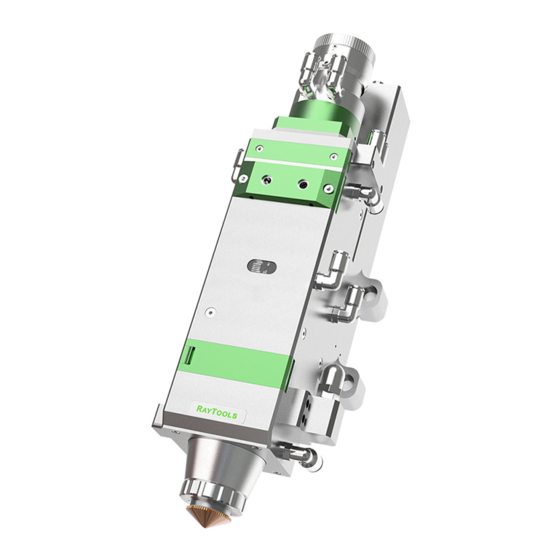
The BM114 series is an automatic focusing fiber cutting head released by Swiss RAYTOOLS AG in 2016. The product is equipped with external servo motor and internal driver units, which can drive the focus lamp to change position automatically in the range of about 25mm by linear mechanism. -
Page 6: Structure & Function
BM114 SERIES 6KW Laser Cutting Head User Manual effect; Equipped with QBH, QD and other fiber interfaces can match with various fiber lasers. Structure & Function As shown in Figure 1, the laser head consists of four basic units, such as collimating module CM, focusing driving module, protective lens module and nozzle module. -
Page 7: Machinery Installation
BM114 SERIES 6KW Laser Cutting Head User Manual 2 Machinery Installation Hole site installation installation BM114 laser machining head and the fixed mounting hole size and position of the machine tool are shown in Figure 3.1. Customers are advised to Install the laser head perpendicular to the machined surface as requested and make sure the laser head is locked, which is one of the premises to ensure the follow up sable cutting effect. -
Page 8: Assist Gas Interface
BM114 SERIES 6KW Laser Cutting Head User Manual 2.2.2 Assist gas interface The impurity in auxiliary gas such as hydrocarbon and steam will damage the lens and cause cutting power fluctuation as well as inconsistencies between the sections of the work piece. The firm below is the recommended auxiliary gas specification. -
Page 9: Connection Of Cutting Head Cable
BM114 SERIES 6KW Laser Cutting Head User Manual Connection of Cutting Head Cable This paper mainly introduces the connection between the cable and the cutting head. The control section of the driver and the connection refer to the wiring diagram of each series of system. -
Page 10: Fiber Insertion And Interface Direction Adjustment
BM114 SERIES 6KW Laser Cutting Head User Manual Fiber Insertion and Interface Direction Adjustment In this paper, an optical fiber insertion method is described in conjunction with a QBH joint. First, align the red point at the end of the QBH interface with the red point of the handwheel; then remove... -
Page 11: System Installation Commissioning
BM114 SERIES 6KW Laser Cutting Head User Manual 3 System Installation Commissioning EtherCAT Installation 3.1.1 Distribution AheadTechs driver + 30W DC motor: The motor is DC servo motor, which should connect the end of the drive L1, L2 respectively with+24V and 0V, and the driver power supply L1C and L2C should connect to 220V exchange L and N.(24V power... -
Page 12: Einterface Settings And Adjustments
BM114 SERIES 6KW Laser Cutting Head User Manual number of upper and lower limit.This pin is defined according to field redundant inputs, or expanded cards) The lower limit is in the biFNegLimit, and the upper limit is on the biFPosLimit. - Page 13 BM114 SERIES 6KW Laser Cutting Head User Manual Figure 4.3 — CNC Interface Verify the servo parameters (the number of pulses per turn, the number of pulses per turn) Inch F axis, check whether the action is normal (from the pitch and direction), 0 scale upward movement of F+.
-
Page 14: Cutting Parameter Setting
BM114 SERIES 6KW Laser Cutting Head User Manual example, -1. Change the parameter point position to -9. Again back to zero, this zero zero position and focal position overlap, change focus finish. After the zero return, the F axis is moved up and down, so that it touches the limit, records the machine tool coordinates, and enter coordinates of the upper and lower limits into the positive focus and negative focus of the F axis. -
Page 15: Bc With Position Mode
BM114 SERIES 6KW Laser Cutting Head User Manual Figure 4.5 — Process interface BC with position mode 3.2.1 Distribution AheadTechs driver + 30W DC motor: The motor is DC servo motor, which should connect the end of the drive L1, L2 respectively with+24V and 0V , and the driver power supply L1C and L2C should connect to 220V exchange L and N.(24V power... -
Page 16: Interface Operation
BM114 SERIES 6KW Laser Cutting Head User Manual Select J axis for detection, open loop point movement control. Move or detect the encoder in the (-14mm~+9mm) stroke to determine the encoder direction. Save the parameters and enter the interface Figure 4.6 — Platform configuration tools 3.2.3... -
Page 17: Bc With Velocity Mode
BM114 SERIES 6KW Laser Cutting Head User Manual Note: 1. Click+, the barrel move upward. When it touches positive limit, click -, then barrel move downward to the negative limit. 2. The direction of origin is negative, and take lower limit as a sampling signal. -
Page 18: Interface Operation
BM114 SERIES 6KW Laser Cutting Head User Manual Figure 4.8— Platform configuration tools 3.3.3 Interface Operation Close to upper limit. Inch J axis after ensure there’s no warning and detect whether the action is normal(distance to “pitch” and direction), 0 scale moving upward is J+ Slow moving J axis so that it touches the positive and negative limit, detect whether the signal and direction is right.(The positive and negative limit wiring has the pipe sleeve mark) -
Page 19: Beam Adjustments And Focusing
BM114 SERIES 6KW Laser Cutting Head User Manual Note: 1. Click +, the barrel move upward, click - when it touches negative limit. The barrel move downward and arrive negative limit. 2. The direction of origin is negative, and take lower limit as a sampling signal. -
Page 20: The Focus Position Adjustment
BM114 SERIES 6KW Laser Cutting Head User Manual The Focus Position Adjustment BM114 is equipped with automated focusing system. But it still need dot manually to redecide the focus position when it reset of replacement of lenses, lasers. For details about operating system parameters, please refer to the system instructions. -
Page 21: Removal And Installation Of Lenses
BM114 SERIES 6KW Laser Cutting Head User Manual the surface of the lens) Put the lens facing to eyes, hold the absorbent cotton stick with the left hand. Wipe the lens gently in single direction, from bottom to top or from left to right, ( Should not be able to wipe back and forth, so as not to secondary pollution of the lens)and use rubber blowing to sway the surface of the lens. -
Page 22: Removal And Installation Of Collimating Lenses
BM114 SERIES 6KW Laser Cutting Head User Manual Figure — Take collimating protective lens Remove the gland of collimating protective lens, pinch the two sides of the drawer-type lens holder and pull out the base of protective lens; Seal the part connected with the components of collimating protective lens with textured paper so as to ... -
Page 23: Removal And Installation Of Focus Lenses
BM114 SERIES 6KW Laser Cutting Head User Manual textured paper so as to prevent the entry of dust; Screw out the collimating lens holder, and remove the spring compression ring and collimator lens with the lens-removing tools; Replace or clean the collimating lenses. -
Page 24: Replace Nozzle Connector
BM114 SERIES 6KW Laser Cutting Head User Manual Remove the spring pressure washer and lens with a lens taking tool; Replace or clean the focus lens. As the direction (arrow) shown in figure 6.9, put the focusing lens and the spring pressure washer in the ... -
Page 25: Replace Nozzle
BM114 SERIES 6KW Laser Cutting Head User Manual 5.3.2 Replace Nozzle Unscrew the nozzle Replace with a new nozzle, and re-tighten it with appropriate force. Do the capacitance calibration once again after replacing the nozzle or ceramic body. - Page 26 BM114 SERIES 6KW Laser Cutting Head User Manual Definition Feedback communication failure Failure description The driver cannot detect the encoder feedback Check whether the encoder lines are connected correctly; Check Measures to be taken whether the selected encoding type (MENCTYPE) is correct;...
-
Page 27: Bm114 System Constitution
BM114 SERIES 6KW Laser Cutting Head User Manual 6 BM114 System Constitution System Constitution (Bus) 26 | 11 V1.1 Shanghai Empower Technologies Co., Ltd. © Copy Right www.empower.cn... -
Page 28: System Constitution (Non-Bus Position Loop -Bc)
BM114 SERIES 6KW Laser Cutting Head User Manual System Constitution (Non-bus position loop -BC) 27 | 11 V1.1 Shanghai Empower Technologies Co., Ltd. © Copy Right www.empower.cn... -
Page 29: System Constitution (Non-Bus Position Loop -Bc)
BM114 SERIES 6KW Laser Cutting Head User Manual System Constitution (Non-bus position loop -BC) 28 | 11 V1.1 Shanghai Empower Technologies Co., Ltd. © Copy Right www.empower.cn... - Page 30 BM114 SERIES 6KW Laser Cutting Head User Manual 29 | 11 V1.1 Shanghai Empower Technologies Co., Ltd. © Copy Right www.empower.cn...
-
Page 31: Mechanical And Optical Configurations Diagram
BM114 SERIES 6KW Laser Cutting Head User Manual 7 Mechanical and Optical Configurations Diagram Cutting Head Shape 30 | 11 V1.1 Shanghai Empower Technologies Co., Ltd. © Copy Right www.empower.cn... - Page 32 BM114 SERIES 6KW Laser Cutting Head User Manual 31 | 11 V1.1 Shanghai Empower Technologies Co., Ltd. © Copy Right www.empower.cn...
-
Page 33: Focus Length
BM114 SERIES 6KW Laser Cutting Head User Manual QBH-100mm 7.1.1 Focus length 150mm FL 200mm FL 18.5mm cushion block 32 | 11 V1.1 Shanghai Empower Technologies Co., Ltd. © Copy Right www.empower.cn...
Need help?
Do you have a question about the BM114 Series and is the answer not in the manual?
Questions and answers