
Related Manuals for Transducer Techniques DPM-3

Summary of Contents for Transducer Techniques DPM-3
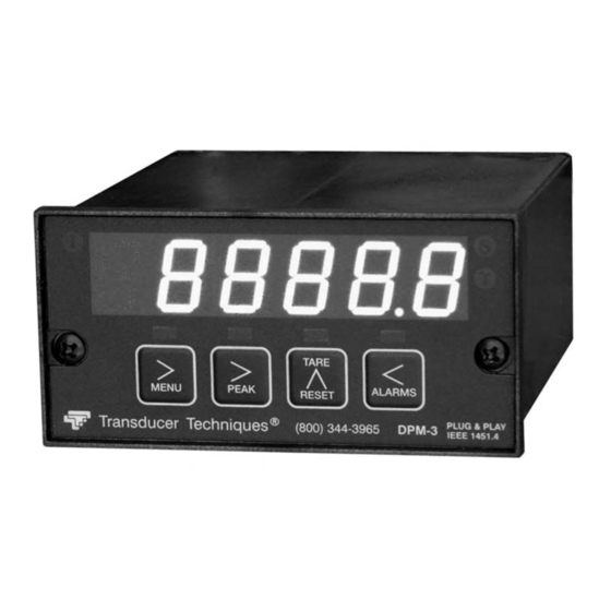
- Page 1 DPM-3 DIGITAL PANEL MOUNT METER PLUG AND PLAY IEEE 1451.4 COMPLIANT OPERATOR MANUAL 4006497 Transducer Techniques...
-
Page 2: Table Of Contents
TABLE OF CONTENTS TEDS IEEE 1451.4 INTRODUCTION ................3 GENERAL INTRODUCTION ..................3 RECEIVING & UNPACKING ..................4 SAFETY CONSIDERATIONS ..................4 CONNECTOR WIRING INFORMATION ..............6 MECHANICAL ASSEMBLY ..................8 FRONT PANEL SETUP KEYS ..................10 ENABLING AND LOCKING OUT MENU ITEMS ............12 TEDS SIGNAL CONDITIONER IN TEDS MODE ............ -
Page 3: Teds Ieee 1451.4 Introduction
TEDS IEEE 1451.4 compliant Load Cell / Torque Sensor and DPM-3 as a system. This includes the configured precision of 32 bits, 19 bits or 11 bits and the configured excitation voltage. Using the DPM-3 with a TEDS IEEE 1451.4 compliant Load Cell / Torque Sensor is as easy as plugging a mouse into a computer, making it a true plug and play experience. -
Page 4: Receiving & Unpacking
PLC’s or other digital devices. An optional USB-to-RS485 converter board allows a primary DPM-3 to be interfaced to a computer and to be the device server for a network of up to 31 other DPM-3’s on an RS485 bus, while itself retaining all capabilities of a meter. - Page 5 that the proper power option is installed for the power to be used. This meter has no AC (mains) switch. It will be in operation as soon as power is connected. The 85-264 Vac mains connector (P1 Pins 1-3) is colored Green to differentiate it from other input and output connectors.
-
Page 6: Connector Wiring Information
5. CONNECTOR WIRING INFORMATION 5.1 CONNECTOR LOCATION Connectors for signal and power are UL-rated screw-clamp terminal blocks that plug into mating jacks on the printed circuit board. Communication connectors can be a USB jack, a single RJ11 jack for RS232, dual RJ11 jacks for RS485, or dual RJ45 jacks for RS485. Note: For wiring color, refer to Load Cell Calibration Certificate or to www.transducertechniques.com/wiring-color-code.aspx - 6 -... - Page 7 P3 - SERIAL COMMUNICATIONS P4 - ANALOG OUTPUT RS232 INTERFACE Computer ISO GND RS485 INTERFACE - FULL DUPLEX RS485 INTERFACE - HALF DUPLEX ISO GND ISO GND ATX / ARX ATX / ARX BTX / BRX BTX / BRX ISO GND ISO GND RS485-MODBUS - FULL DUPLEX RS485-MODBUS - HALF DUPLEX...
-
Page 8: Mechanical Assembly
6. MECHANICAL ASSEMBLY REMOVING THE REAR PANEL First remove any connectors. Use one hand to press in the two sides of the rear of the case, and the other hand to press down the two protruding tab releases at the top of the rear panel (see figure below). - Page 9 Insert the meter in the panel cutout. Turn the mounting screws clockwise until the meter is securely mounted in the panel. Do not overtighten. The DPM-3 uses UL / VDE rated detachable screw terminal connectors for signal and power. - 9 -...
-
Page 10: Front Panel Setup Keys
(Value select) Meter Front Panel TEDS INDICATOR On steady when DPM-3 has detected a TEDS sensor, has read the EEPROM, and has performed an automatic meter configuration. CALIBRATION INDICATORS The following two indicators are active when the Calibration indicators are enabled by the tArE menu item: 1. - Page 11 KEYS IN MENU MODE In the Menu Mode, pressing a key momentarily advances to the next menu item. Holding down a key automatically advances through multiple menu items for fast menu navigation. (Menu). Pressing MENU steps the meter through all menu items that have been enabled and then back to the Run Mode.
-
Page 12: Enabling And Locking Out Menu Items
With the jumper removed, the operator has access to menu headers Loc 1-4 and hence to the menu items below. Check lockout status. DPM-3 meters may have lockouts in place. This causes menu items described in this manual not to appear. -
Page 13: Teds Signal Conditioner In Teds Mode
9. TEDS SIGNAL CONDITIONER IN TEDS MODE 9.1 INTRODUCTION The DPM-3 is a TEDS IEEE 1451.4 Plug and Play Smart Load Cell Meter. TEDS, or Transducer Electronic Data Sheet, is a set of electronic data in a standardized format defined within the IEEE 1451.4 standard that is stored in an EEPROM. This data specifies what type of sensor is present, describes its interface, and gives technical information such as sensitivity, bridge type, excitation, etc. - Page 14 9.4 Software TEDS Reader-Editor Software, P/N DPM-3-TRES, is available from Transducer Tech- niques. This software allows the user to read and edit information stored in the TEDS transducer. See Section 24 "Accessories" for ordering information. 9.5 Meter Setup When setting up the meter, it may be necessary to enable some of the menu items.
- Page 15 DIGIT VALUE MENU SELECT KEY SELECT KEY FiLtr 00000 Alarm unfiltered Filtering Alarm filtering Alarm filtered 00000 Peak & Valley unfiltered Peak & Valley filtering Peak & Valley filtered 00000 Display batch average every 16 readings Display filtering Display filtered signal 00000 Low adaptive filter threshold level Adaptive filter threshold...
- Page 16 DIGIT VALUE MENU SELECT KEY SELECT KEY Option board dependent menu items _Addr Menu items related to serial communications. These will only appear if an RS232, RS485, or USB I/O board is detected. If so, see Section 16. CAL rt The Cal Instrument indicator starts flashing 30 days before instrument Cal Reset...
-
Page 17: Setup Of Non-Teds Transducers
10. SETUP OF NON-TEDS TRANSDUCERS 10.1 SCALING METHODS Three methods are selectable for scaling the meter, as follows: Scale and Offset Method (using calculated scale and offset). This method requires that you calculate the required scale and offset values and enter them into memory when the meter displays SCALE and OFFst. -
Page 18: Meter Scaling By Applying Known Loads
11. METER SCALING BY APPLYING KNOWN LOADS Apply power and press the left MENU key until SEtuP appears on the display. Press the PEAK key, and 4 digits will appear on the display. Continue pressing the PEAK key until the Digit 4 begins to flash _00_20. Make this digit a 2 by pressing the RESET key until 2 appears. -
Page 19: Teds Signal Conditioner With Non-Teds Transducers
12. TEDS SIGNAL CONDITIONER WITH NON-TEDS TRANSDUCERS MENU DIGIT SELECT VALUE SELECT KEY InPut _Strn_ Input signal Load cells. Factory de- __20.0 __50.0 _100.0 _250.0 _500.0 type fault scaling is 50 mV FS 20, 50, 100, 250, 500 mV full scale. _dC u DC millivolts SEtuP... - Page 20 DIGIT SELECT MENU VALUE SELECT KEY ConFG 000_0 Not rate of change Meter Operation as a rate of Rate x 0.1 Configuration change meter. Rate x 1 Rate x 10 Extended meter only. Rate x 100 Rate x 1000 Rate x 10000 Peak Display.
- Page 21 DIGIT SELECT MENU VALUE SELECT KEY Scaling method “Scale and Offset” if selected under SEtuP Select thru for flashing first digit, thru SCALE 0.0000 0.0000 0.0000 Scale factor for other flashing digits. Select decimal point 0.0000 0.0000 0.0000 location when decimal point is flashing. Select digit to flash.
- Page 22 Option board dependent menu items ALSEt. ALS34 dEU1H dEU2H dEU1b dEU2b dEU3H DEU4H DEU3b DEU4b Menu items related to alarm setup These will only appear if a relay board is detected. If so, please see Section14. AnSEt. Hi.. Menu items related to analog output setup. These will only appear if an analog output board is detected.
-
Page 23: Load Cell & Microvolt Signal Conditioner
13. LOAD CELL & MICROVOLT SIGNAL CONDITIONER This section provides setup instructions to set up the DPM-3 signal conditioner for use with load cells or strain gauges, or as a microvolt meter. The meter’s built-in, isolated 10 Volt, 120 mA excitation supply will power up to four 350 ohm load cells in parallel. - Page 24 DIGIT SELECT MENU KEY VALUE SELECT KEY _InPut _Strn _0020.0 Press key until Strn Press to display InPut Press to select 20.0, (ratiometric) is displayed. (input type). 50.0, 100.0, 250.0 or 500.0 _SEtuP _30_00 _00_10 12345 Press to display SEtuP Press to select digit, (basic setup).
-
Page 25: Dual Relay Output Option
14. DUAL OR QUAD RELAY OUTPUT OPTION An optional relay board may be installed in the meter main board at plug position P2, adjacent Alarm status to the power supply board. Four board ver- indicators sions are available: 2 or 4 relays, mechanical 1 through 4 or solid state. - Page 26 KEYSTROKES FOR SETPOINT SETUP key does not work, see Section 8 “Enabling & Locking Out Menu Items.” If the MENU DIGIT SELECT MENU KEY VALUE SELECT KEY 00000 Relay 1 on Relay 2 on ALSEt Alarm Setup for Relay state when Relay 1 off Relay 2 on relays 1 &...
- Page 27 VALUE SELECT MENU KEY DIGIT SELECT KEY ALS34 00000 AL3 active high AL4 active high Alarm Setup for Alarm operates at and AL3 active low AL4 active high relays 3 & 4 above setpoint (active AL3 disabled AL4 active high (continued) high) or at and below AL3 active high...
-
Page 28: Analog Output Option
15. ANALOG OUTPUT OPTION An optional analog board may be installed in the meter at rear panel jack position J4, adjacent to the signal conditioner board. Once installed, this board is recognized by the meter, which will bring up the appropriate menu items for it. These will not be brought up if an analog output board is not installed. -
Page 29: Serial Communication Options
16. SERIAL COMMUNICATION OPTIONS A serial communications board may be connected to the DPM-3 meter main board at plug position P13 (middle position). Available boards are RS232, RS485 (with dual RJ11 connec- tors), RS485 Modbus (with dual RJ45 connectors), USB, and a USB-to-RS485 converter. The dual connectors of RS485 boards are wired in parallel to allow daisy chaining of addressable meters without the use of a hub. - Page 30 BOARD SETUP VIA JUMPERS USB Board No jumpers required. RS232 Board e - RTS enabled by external source (otherwise always enabled). f - Slave display to RS232 from another meter. g - Required for RS232 operation. Note: Board is shipped with jumpers e and g installed RS485 Board, Full Duplex Operation b &...
- Page 31 KEYSTROKES FOR SETUP key does not work, see Section 8 “Enabling & Locking Out Menu Items.” If the MENU DIGIT SELECT MENU KEY VALUE SELECT KEY __000 Send unfiltered signal .SEr Fixed Parameters: Output filtering Send filtered signal No parity __000U 300 baud 8 data bits...
- Page 32 DIGIT SELECT MENU KEY VALUE SELECT KEY .SEr 00000U Reading Serial Setup 3 Data sent in continuous Peak (continued) mode Valley Reading + peak Reading + valley Reading + peak + valley __000U 1 sec Serial Setup 4. Modbus ASCII gap timeout 3 sec 5 sec 10 sec...
- Page 33 SERIAL CONNECTION EXAMPLES - 33 -...
-
Page 34: Excitation Outputs & Power Supply
17. EXCITATION OUTPUTS & POWER SUPPLY Three isolated transducer excitation output levels are available from the power supply board. These are selectable via jumpers b, c, d, e, f in the upper right of the board, as illustrated. In addition, the board provides three jumper positions for special features. The same jumper locations apply to the universal power supply (85-264 Vac) and to the low voltage power supply (12-32 Vac or 10-48 Vdc). -
Page 35: Digital Control Inputs
18. DIGITAL CONTROL INPUTS 18.1 FUNCTION OF DIGITAL INPUTS Logical 0 Current display value is set to zero and is stored as offset value. Logical 1 Displayed value equals signal input less tare value. Logical 0 Peak or Valley value of input signal is displayed. Logical 1 Current value of input signal is displayed. -
Page 36: Instrument Setup Via Pc
19. INSTRUMENT SETUP & DATA DISPLAY VIA PC DPM-3 Instrument Setup software is a PC program which is much easier to learn than front panel programming. It is of benefit whether or not the meter is connected to a PC. With the... - Page 37 PC can be a major time saving when multiple meters have to be set up in the same way. You will find that DPM-3 Instrument Setup software is very user friendly, with separate tab- selectable windows for Input+Display, Scaling, Filter, Relay Alarms, Communications, Analog Out, and Lockouts.
- Page 38 PC is not connected to a meter. Upon launch- ing the software, click on None for Communications, then on DPM-3 and Continue. Click on File => Default Setup to retrieve a default setup file from disk, or on File =>...
-
Page 39: Custom Curve Linearization
3) A USB or RS232 board in the meter. This board can be used for meter setup only, then be removed. 4) USB cable, A to B, or RS232 cable, RJ11-to-DB9 (P/N DPM-3-RJ11AD9), to connect the meter and PC. 5) Curve.exe software, available from Transducer Techniques. - Page 40 4) Equation entry mode, where the coefficients of a polynomial Y = K1X^P1 + K2X^P2 + K3*X^P3 + … are entered. Up to 20 terms are allowed. An offset can be built into X. You will be asked if your DPM has a revision of DPM4L or later. You will normally select 2 (yes), since revision DPM4L started to ship in August 2000.
-
Page 41: Meter Calibration
21. METER CALIBRATION All analog input and analog output ranges of the meter have been digitally calibrated at the factory prior to shipment using calibration equipment certified to NIST standards. Calibration constants are stored digitally in non-volatile memory in EEPROM on the signal conditioner board and analog output board. - Page 42 Accuracy Output Zero Output Span Input Range Resolution Error at 25°C Range Range 20.000 mV 1 µV 50.000 mV 2.5 µV -99,999 0.01% of 100.00 mV 5 µV Full Scale 250.00 mV 12.5 µV +99,999 ±99,999 ±2 counts 500.00 mV 25 µV Span Tempco (load cell signal conditioner) ..........
- Page 43 Form A, SPST Solid State Relay Output: AC Rating ....................120 mA @ 140 Vac DC Rating ....................120 mA @ 180 Vdc Isolation rating between signal common and contacts ..........250V ac Insulation dielectric strength between signal common and contacts ...........................
-
Page 44: Glossary Of Terms
23. GLOSSARY OF TERMS Adaptive Filter Threshold A threshold which causes an adaptive moving average filter to be reset to the latest reading when the accumulated difference between individual readings and the filtered reading exceeds that threshold. Adaptive moving average filtering allows the meter to respond rapidly to actual changes in signal while filtering out normal noise. - Page 45 Setting up a passband around a setpoint is often used for component testing. Deviation limits are programmed by entering menu item dEU1b for Alarm 1 and dEU2b for Alarm 2. The deviation band will be equal to two limits. Display Blank A rear panel input which blanks the display when the input is tied to logic ground by a switch or 0V is applied (logic level true).
- Page 46 Menu Mode The meter programming mode used for input and range selection, meter setup, and meter configuration. Entered into from the Run mode by pressing the MENU key. The Menu mode can be locked out completely by a jumper. Meter Hold A rear panel input which freezes the meter display and all meter outputs while that input is tied to logic ground by a switch or is held at 0V (logic level true).
- Page 47 Remote Display A display mode which allows the meter to serve as a remote display to another meter when connected to it by a 4-wire phone cord. Also allows the meter to transmit raw measurement data to a computer and then display processed data from the computer.
- Page 48 Scaling, Reading Coordinates of 2 Points Method A scaling method, where the low and high input values are determined from actual signals. A known low signal is first applied to the meter, such as the output of a pressure transducer at zero pressure. That signal is captured as the low input value, and the desired low reading is entered.
- Page 49 Valley Display The minimum (or most negative) reading since that minimum was last reset. Reset can be via the meter front panel, an external input, or a software command. The displayed value can reflect the filtered or unfiltered readings. Zero An adjustment so that a given low transducer output reads zero on the meter.
-
Page 50: Accessories
24. ACCESSORIES - 50 -... - Page 51 DPM-3-PC6 & DPM-3-PC12 Power Cable to Meter DPM-3-RJ11AD9 RS232 Data Cable, PC to Meter USB-2.0-A/B USB Cable, Type A/B, 10 ft. DPM-3-DLS Data Logging Software DPM-3-TRES TEDS Reader_Editor Software DPM-3-SPC Splash Proof Cover. Seals meter against instrument panel. - 51 -...
-
Page 52: Warranty & Repair Policy
Any of our products which, under normal operating conditions, proves defective in material or in workmanship within one (1) year from the date of shipment by Transducer Techniques, will be repaired or replaced free of charge provided that you obtain a return material... - Page 53 Load Cells Force/Torque Sensors (800) 344-3965 E-mail: tti@ttloadcells.com www.transducertechniques.com Transducer Techniques Temecula, CA 92590...
Need help?
Do you have a question about the DPM-3 and is the answer not in the manual?
Questions and answers