
Related Manuals for Transducer Techniques SSI

Summary of Contents for Transducer Techniques SSI
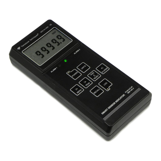
- Page 1 SMART SENSOR INDICATOR PLUG & PLAY IEEE 1451.4 COMPLIANT OPERATOR MANUAL (USB)
-
Page 2: Table Of Contents
1. TABLE OF CONTENTS TABLE OF CONTENTS ....................2 TEDS IEEE 1451.4 INTRODUCTION ................3 SSI PRODUCT INTRODUCTION ................4 RECEIVING & UNPACKING ..................6 SAFETY CONSIDERATIONS & CARE OF YOUR METER ......... 8 CONNECTOR WIRING INFORMATION ..............10 KEYPAD OPERATION ....................12 “dAtE”... -
Page 3: Teds Ieee 1451.4 Introduction
2. TEDS IEEE 1451.4 INTRODUCTION The SSI Smart Sensor Indicator is a TEDS IEEE 1451.4 Plug and Play Smart Load Cell Meter. TEDS, or Transducer Electronic Data Sheet, is a set of electronic data in a standardized format defined within the IEEE 1451.4 standard. The data is stored in an EEPROM with the sensor. -
Page 4: Ssi Product Introduction
3. SSI PRODUCT INTRODUCTION The SSI Smart Sensor Indicator is a hand-held, programmable meter and datalogger for load, torque or pressure applications. Advanced capabilities include: “Plug and Play” operation with automatic scaling at power-up with TEDS IEEE 1451.4 compliant load cells. - Page 5 18. Data logging of time and date stamped values in real time via USB to a PC or printer. The values may be the current reading, Peak, Valley, or any combination thereof. 19. Optional PC Data Logging Software, P/N SSI-DLS. Collects real-time or stored data via USB. Lists, plots or stores meter data in PC memory.
-
Page 6: Receiving & Unpacking
4. RECEIVING & UNPACKING Your SSI was carefully tested and inspected prior to shipment. Should your unit be damaged in shipment, keep the shipping materials and notify the freight carrier immediately. Verify that your SSI shipment includes the following items: 1. - Page 7 SSI-DLS Data Logging Software SSI-TRES TEDS Reader Editor Software Available for download from www.transducertechniques.com at no charge: 1. SSI-IS Instrument Setup Software. 2. SSI Operator Manual (USB) This manual in pdf format. - 7 -...
-
Page 8: Safety Considerations & Care Of Your Meter
5. SAFETY CONSIDERATIONS & CARE OF YOUR METER The SSI is housed in a tough ABS case and is mechanically rugged. The LCD display is protected by a clear Lexan cover. The unit is powered by a rechargeable lithium-ion battery. - Page 9 Symbols used Caution (refer to accompanying documents) Caution, risk of electric shock. Earth (ground) terminal. Equipment protected throughout by double insulation or reinforced insulation. Both direct and alternating current. CE Mark. Indicates that product meets EU safety, health and environmental requirements.
-
Page 10: Connector Wiring Information
6. CONNECTOR WIRING INFORMATION Type B USB connector Detachable screw-clamp plug for digital control inputs A & B: External B Ground External A Detachable screw-clamp plug for dual relay outputs 1 & 2: Normally Open 2 Common Normally Open 1 DB9 connector for excitation output, signal input, and TEDS interface - 10 -... - Page 11 Name Description VBUS Data - Data + Ground Relay Jack Pinout (looking into jack) Industry Standard USB Pinout - 11 -...
-
Page 12: Keypad Operation
7. KEYPAD OPERATION GENERAL The SSI operator panel consists of an LCD display, an 8-key membrane keypad, and 5 LED indicator lights, as explained below. LCD DISPLAY 8.8.8.8.8.8. Main reading. This can be the current reading, recalled read- ing, first peak, peak, or valley, as selected via the keypad. - Page 13 TEDS Indicates that a TEDS sensor is present, as detected by a jumper across pins 3 and 4 of the DB9 connector, and that plug & play has been selected. FIRST PEAK Indicates that main reading is First Peak (or first maximum) since last reset. PEAK Indicates that main reading is the Peak (or maximum) since last reset.
- Page 14 From the RUN mode, press momentarily to log the current reading into the next available Memory location # (from 0 to 15999). Press for longer than 2 seconds to place the meter in the Continuous Logging mode, which will log multiple readings at a programmable data collection rate.
- Page 15 To reset the meter, hold the key depressed while you press and TARE ^ RESET release the key. > MENU To reset a Peak, Valley or First Peak, hold the key depressed TARE ^ RESET while you press and release the key.
-
Page 16: Date" Error Message
8. “dAtE” ERROR MESSAGE The "dAtE" menu item appears as an error message following meter reset when the meter determines that the date in the meter is in error. This can result from a deeply discharged battery or entry of an incorrect “dAtE" value. To restore normal operation, use the PEAK and RESET keys to enter the correct current “dAtE"... -
Page 17: Data Logging & Recall Operation
9. DATA LOGGING & RECALL OPERATION 1. Modes of Operation Two modes of operation are associated with logging: RUN mode: The meter is converting and displaying readings. Logging may or may not be taking place simultaneously. RECALL mode: The meter is not converting. Previously stored values are displayed on the meter and may be transmitted via USB. - Page 18 LOG Key, Long Push Displayed readings are continuously logged to successive Memory location #’s and to USB at the Menu-selected output rate. The Green LED, the Memory # and USB label remain on continuously. RECALL Key, Short Push If Continuous logging is off, a header record consisting of Date, Time Units and Value Type is transmitted via USB.
- Page 19 LOG Key, Long Push Transmits the displayed Value and selected non-value data items over USB, then advances the Memory #. This is repeated continuously until the key is RECALL given a Short push to turn off Continuous Recall. The Green LED, Memory # and USB label remain on during continuous transmission.
- Page 20 Logging to USB For more detailed information, download the SSI Serial Communications Manual from the www.transducertechniques.com website. For each logged record, only the selected data items are transmitted via USB. All of the non-Value data items are optional, but the Value selection made from the menu item SEr_3, Digit 5 as shown below is always included.
- Page 21 record via USB. The minimum number of bytes per record is 8 (1 Value only). The maximum number of bytes per record is 59 (all selected). Data Items & Stored in Bytes Memory Selection Values Implied LoG, Digit 3 Memory # LoG, Digit 2 Date LoG, Digit 2...
- Page 22 7. Data Recall Data Logging Software (P/N SSI-DLS) is available from www.transducertechniques.com for download. This software is needed to recall stored data from the meter. It lists, plots or stores meter data in PC memory. Recall initiated by the Log key or a control input while in the RECALL mode. The meter sends the Memory # and stored Value to the display.
-
Page 23: Menu Mode Programming Fundamentals
TEDS related menu items do not appear if TEDS Plug-and-Play operation has been disabled. The alternative to Menu Mode programming is to use SSI Instrument Setup software, a Win- dows application that runs on PC which is connected to the meter via USB. This software is available for download. - Page 24 2. Conversion Rate Eight conversion rates are selectable, consisting of one “Normal” and seven “Fast.” The Normal rate is 60 (60 Hz noise rejection) or 50 (50 Hz noise rejection) conversions per second. Each conversion consists of the average of 256 samples. The sample rate is 15,360 samples/second for 60 Hz and 12,800 samples/second for 50 Hz.
- Page 25 5. Noise Filtering Since electrical noise is often a factor with millivolt signals, the SSI offers programmable features so that a user can make the best compromise between noise rejection and meter response rate for the application and noise environment. Note: Noise filtering is only available at Normal conversion rates of 60 or 50 Hz.
- Page 26 > PEAK 7. Alarms The SSI includes two solid state alarm relays rated 110 mA @ 350V peak, 35 ohms series resistance. There is a common contact for the two relays. The active state of alarms is shown by LED indicators: amber for Alarm 1, red for Alarm 2, and green for “Go” with no alarm active.
- Page 27 CALrt from a 1 to a 0. The operation applies to the TEDS sensor that is actively connected to the SSI unit. If a TEDS sensor is not connected or Plug and Play is not selected, the indicator does not appear.
-
Page 28: Menu Mode Programming Keystrokes
11. MENU MODE PROGRAMMING KEYSTROKES The five menu items on this page will appear first when the key is first pressed from > MENU the RUN mode if the following conditions apply: 1. The transducer is a non-TEDS transducer or a TEDS transducer where Plug & Play operation has been disabled. - Page 29 In-oz Inch-ounce In-lb Inch-pound ft-lb Foot-pound torque Units of torque kgf-m Kilogram-meter Newton-meter kgf-cm Kilogram-centimeter N-cm Newton-centimeter Pascal PrESSr Units of Pounds per sq. inch pressure 0 60 Hz environment 0_00 Noise rejection 1 50 Hz environment 0 Not used 0_00 Scaling method.
- Page 30 0 Peak (Normal or Fast rate) 1 First Peak (Normal or Fast rate) 00000 Displayed value in response to pressing 2 Valley (Normal rate only) key. > PEAK 3 Peak (1 push), Valley (2 push) (Normal rate only) 00000 Peak polarity. 0 Positive Peak Applies only to Fast con- 1 Negative Peak...
- Page 31 The next 5 menu items are for the “Coordinates of 2 Points” scaling method if selected under SEtuP. The more popular “Reading Coordinates of 2 Points” scaling method will appear at the beginning of the menu items if selected under SEtuP. Neither scaling method will appear if custom curve linearization is selected or if TEDS Plug &...
- Page 32 0 AL1 non-latch AL2 non-latch 00000 Relay reset 1 AL1 latching AL2 non-latch mode: non-latching (auto-reset), latching 2 AL1 non-latch AL2 latching (requires manual reset). 3 AL1 latching AL latching 0 AL1 active high AL2 active high 1 AL1 active low AL2 active high 2 AL1 disabled AL2 active high...
- Page 33 000 Sent value 0 Unfiltered* 1 Filtered source 0 300 baud 4 4800 baud 1 600 baud 5 9600 baud 000 Serial baud rate SEr_1 Serial Config 1 2 1200 baud 6 19.2 kbaud Fixed Parameters: 3 2400 baud 7 38.4 kbaud No parity 0 60 / sec 8 1 / 34 sec...
- Page 34 0 Do not send Units or Value Type. 00000 Units of measure and Value Type logged 1 Send Units, not Value Type. via serial communications. 2 Send Value type, not Units. 3 Send both Value type and Units. 0 Don’t send Time or Date. 00000 Time and Date logged via serial commu- LoG Data Logging.
- Page 35 The 6 menu items below are read from the TEDS transducer and are read-only. CALd Calibration date of TEDS sensor in MM.DD.YY format. SErno Serial number of transducer. Up to 8 digits in two groups of digits. Unit of measure, same as on LCD display. Units CALInL.
-
Page 36: Instrument Setup & Data Display Via Pc
12. INSTRUMENT SETUP & DATA DISPLAY VIA PC SSI Instrument Setup is a PC program that greatly facilitates meter setup whether the meter is or is not connected to a PC: Connected use allows uploading, editing and downloading of setup data and execution of commands under computer control. - Page 37 The best way to learn SSI Instrument Setup is to experiment with it. From the Main Menu, click on Meter > Get Setup to retrieve the existing setup data from the meter. Click on View >...
-
Page 38: Custom Curve Linearization
1) PC-compatible computer with an available USB port. 2) An A-B USB cable to connect the meter and PC. A suitable cable is the one that comes with the AC adapter SSI-USB/ACA. 3) Curve.exe software (downloadable from website). GETTING STARTED Download curve.exe into the same directory that will contain your data files, such as... - Page 39 3) 2-coordinate file entry mode, where an actual X input signal is applied, and the desired Y reading is provided from a file. 4) Equation entry mode, where the coefficients of a polynomial Y = K1X^P1 + K2X^P2 + K3*X^P3 + … are entered. Up to 20 terms are allowed. An offset can be built into X. You will be asked to supply the following: LOW X-COORDINATE VALUE >...
-
Page 40: Meter Calibration
UNITS The instrument calibration indicator (CAL INSTRUMENT) indicates when the meter is due for calibration. The SSI also features a clearable flashing indicator when the meter is within 30 days of the calibration due date. Annual recalibration by the factory is recommended. Please contact Transducer Techniques for an RMA number. -
Page 41: Specifications
16. SPECIFICATIONS Display Type ............Reflective LCD, 2.56” x 1.73” (65 x 44 mm) window Main numeric display ........6 seven-segment digits, 0.57” (14.5 mm) high Other displayed items ......5-digit recall number, choice of 18 units of measure, battery life indicator, operating mode indicator Overload indication ............ - Page 42 Battery charge indication ....Battery symbol with 4 bars to show percent of full charge 4 bars = 80% - 100%, 3 bars = 60% - 80%, 2 bars = 40% - 60%, 1 bar = 20% - 40%, flashing battery symbol = 0% - 20% Relay Output Relay types ............
- Page 43 Peak-to-Peak Noise as a Percentage of Full Scale Load cell sensitivity Conversion Filter Filter time type setting constant 1 mV/V 2 mV/V 3 mV/V 4 mV/V Normal No filter 0.03 0.02 0.01 < 0.01 Normal 16 conv. batch avg. < 0.01 <...
-
Page 44: Glossary Of Terms
17. GLOSSARY OF TERMS Adaptive Filter Threshold A threshold which causes an adaptive moving average filter to be reset to the latest reading when the accumulated difference between individual readings and the filtered reading exceeds that threshold. Adaptive moving average filtering allows a meter to respond rapidly to actual changes in signal while filtering out normal noise. - Page 45 The normal operating mode of the meter, where readings are taken, as opposed to the Menu or Recall modes. Sampling Rate The rate at which data is collected for further processing. In the SSI, this is 15,360 samples/second. Scaling The setup process which relates signal inputs to numeric readings in engineer- ing units (such as psi).
- Page 46 Setpoint A value compared to the reading to force the state of a relay. Term often used interchangeably with “alarm setpoint.” The relay action can be latching or non- latching and utilize a hysteresis band or deviation band. Hysteresis bands and deviation bands are specified by two symmetrical limits around the setpoint.
-
Page 47: Warranty & Repair Policy
Temecula, CA. Please return the original calibration data with the unit. Repair Warranty All repairs of Transducer Techniques’ products are warranted for a period of 90 days from the date of shipment. This warranty applies only to those items that were found defective and repaired;... - Page 48 Load Cells Force/Torque Sensors (800) 344-3965 E-mail: tti@ttloadcells.com www.transducertechniques.com Transducer Techniques Temecula, CA 92590...
Need help?
Do you have a question about the SSI and is the answer not in the manual?
Questions and answers