
Related Manuals for Faller 161352

Summary of Contents for Faller 161352
- Page 1 161351/161352 PC-Grundmodul/Erweiterungsmodul 161351/161352 PC-standard module/ Expansion module Bedienungsanleitung Instruction Manual...
-
Page 2: Table Of Contents
Inhalt FALLER Car System – Jetzt wird’s digital ........... 3 Sicherheit und Verantwortung ............4 Bestimmungsgemäßer Gebrauch ............4 Zu Ihrer Sicherheit ................4 Umweltgerecht entsorgen ..............5 Produktübersicht ................6 Lieferumfang ................... 6 Bestandteile des PC-Grundmoduls ........... 7 Bestandteile des Erweiterungsmoduls ..........8 Grund- und Erweiterungsmodul anschließen ........ -
Page 3: Faller Car System - Jetzt Wird's Digital
FALLER Car System – Jetzt wird’s digital Herzlichen Glückwunsch – Sie sind fündig geworden! Mit den Steuerungsmodulen aus der FALLER Digital-Serie haben Sie ab sofort die Möglichkeit Ihre Funktionselemente auf der Modellanlage über eine Digitalzentrale oder einen PC zu steuern. -
Page 4: Sicherheit Und Verantwortung
Sammler und kein Spielzeug. Das Produkt ist dazu bestimmt, im Rahmen einer Modellanlage eingesetzt zu werden. Es darf ausschließlich mit den von FALLER dafür empfohlenen Zubehörartikeln bzw. Anbauten betrieben wer- den. FALLER-Produkte sind grundsätzlich für den Hobbygebrauch konzipiert und konstruiert, nicht für den Dauerbetrieb. Das Produkt ist dazu bestimmt, bei durchschnittlicher Raumtemperatur und Luftfeuchte eingesetzt zu wer- den. -
Page 5: Umweltgerecht Entsorgen
Sicherheit und Verantwortung Halten Sie die Bedienungsanleitung und die beiliegenden Sicherheits- hinweise beim Produkt verfügbar. Geben Sie das Produkt nur zusammen mit der Bedienungsanleitung und mit den beiliegenden Sicherheitshinweisen an Dritte weiter. WEEE-Hinweis (Umweltgerecht entsorgen) Produkte, die mit einem durchgestrichenen Mülleimer-Symbol gekennzeich- net sind, dürfen am Ende ihrer Lebensdauer nicht über den normalen Haus- haltsabfall entsorgt werden, sondern müssen an einem Sammelpunkt für das Recycling von elektrischen und elektronischen Geräten abgegeben werden. -
Page 6: Produktübersicht
Produktübersicht Produktübersicht Lieferumfang PC-Grundmodul (nur in Artikel 161351) ƒ Erweiterungsmodul (nur in Artikel 161352) ƒ CD-ROM (nur in Artikel 161351) ƒ Anleitung ƒ... -
Page 7: De Bestandteile Des Pc-Grundmoduls
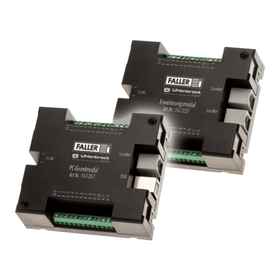
Produktübersicht Bestandteile des PC-Grundmoduls Abb. 1: PC-Grundmodul Anschlüsse Beschreibung »16 VAC« Anschluss für die Spannungsversorgung (16 V Wechselspannung) »USB« USB PC-Anschluss »LocoNet« LocoNet Schnittstelle »E 1 - E 11« 11 Eingänge »0 V« 0 V für Eingänge »A 1 - A 12« 12 Ausgänge »15 V«... -
Page 8: Bestandteile Des Erweiterungsmoduls
Produktübersicht Bestandteile des Erweiterungsmoduls Abb. 2: Erweiterungsmodul Anschlüsse Beschreibung »16 VAC« Anschluss für die Spannungsversorgung (16 V Wechselspannung) »LocoNet« LocoNet Schnittstelle »E 1 - E 11« 11 Eingänge »0 V« 0 V für Eingänge »A 1 - A 12« 12 Ausgänge »15 V«... -
Page 9: Grund- Und Erweiterungsmodul Anschließen
Die Module werden mit 16 V Wechselspannung betrieben. TIPP Die notwendige Wechselspannung können Sie zum Beispiel mit dem FALLER Transformator 50 VA, 50-60 Hz, Artikelnummer 180641, erzeugen. Abb. 3: Anschlussseite Schließen Sie die Module an 16 V Wechselspannung an, siehe Abb. 3. -
Page 10: Rückmeldekontakte Anschließen
Die Eingänge der Module müssen alle »potentialfrei« geschaltet werden. TIPP Hier können Taster, Sensoren, Schaltgleise oder die potentialfreien Ausgänge von Schaltdecodern angeschlossen werden. Für die Rück- meldung aus der Straße verwenden Sie FALLER-Sensoren, Artikel- nummer 161773. ACHTUNG Schließen Sie niemals spannungsführende Komponenten, wie z.B. die Aus- gänge eines Weichendecoders, an den Eingängen der Module an. -
Page 11: Funktionselemente Anschließen
Testen Sie dies, indem Sie den Lenkschleifer über das Zentrum der eingeschalteten Stopp-Stelle bewegen. Wird der Lenkschleifer abgesto- ßen, ist der Nordpol oben. Soll dagegen ein Fahrzeug der FALLER Digi- talserie an dieser Stelle seine zweite Fahrstufe abrufen, muss der Südpol nach oben weisen. - Page 12 Grund- und Erweiterungsmodul anschließen Abb. 5: Schraubklemme 15 V Abb. 6: Schraubklemme 20 V Abb. 7: Schraubklemme Ausgang (A1 - A12). Bsp. 20 V Schließen Sie eines der Anschlusskabel des Verbrauchers an die dafür vorgesehene Spannung (15 V / 20 V) an, siehe Abb. 5 und Abb. 6. Schließen Sie das andere Ende des Verbrauchers am gewünschten Aus- gang an, siehe Abb.
-
Page 13: Pc-Verbindung Herstellen
Grund- und Erweiterungsmodul anschließen PC-Verbindung herstellen Das PC-Grundmodul verfügt über eine USB-Schnittstelle, über welche es mit Hilfe eines handelsüblichen Druckeranschlusskabels (USB-A auf USB-B, liegt nicht bei) mit einem PC verbunden werden kann. ACHTUNG Bevor das Modul mit dem PC verbunden wird, muss der Treiber auf der beiliegenden CD installiert werden, da es sonst zu fehlerhaften Einstel- lungen im Betriebssystem kommen kann. -
Page 14: Weitere Loconet-Module Anschließen
ƒ späteren Nummerierung. Achten Sie darauf, dass alle Module nacheinander angeschlossen werden. ƒ Module von FALLER und Module anderer Anbieter können miteinan- der kombiniert werden. Das Erweiterungsmodul kann auch direkt an eine LocoNet-fähige Digi- ƒ talzentrale (z.B. Uhlenbrock Intellibox II) angeschlossen und darüber betrieben werden. - Page 15 Verbinden Sie dann das LocoNet Kabel mit einem der LocoNet- Anschlüsse des zweiten Moduls, siehe Abb. 11. TIPP LocoNet-Kabel (z.B. von Uhlenbrock) erhalten Sie im gut sortierten Modell-Fachhandel. TIPP Der direkte Draht zum FALLER-Kundendienst: Telefon + 49 (0) 77 23 / 651-106 E-Mail kundendienst@faller.de...
-
Page 16: Treiber- Und Softwareinstallation
Treiber- und Softwareinstallation Treiber- und Softwareinstallation Systemvoraussetzungen PC mit Betriebssystem Windows 2000 oder neuer ƒ Freie USB Schnittstelle ƒ 30 MB freier Festplattenplatz ƒ Software installieren ACHTUNG Bevor das Modul mit dem PC verbunden wird, muss der Treiber von der beiliegenden CD auf Ihrem PC installiert werden, da es sonst zu fehler- haften Einstellungen im Betriebssystem kommen kann. -
Page 17: Die Software »Car System 2
Die Software »Car System 2« Die Software »Car System 2« Bei der Software »Car System 2« handelt es sich um ein Programm, das Sie bei der Einrichtung Ihrer Module unterstützt. Mit Hilfe dieser Software kön- nen Sie ganz einfach anhand der grafischen Benutzeroberfläche Modulnum- mern, Digitaladressen und Rückmeldenummern vergeben. -
Page 18: Das Anwendungsfenster
Die Software »Car System 2« Das Anwendungsfenster Abb. 12: Das Anwendungsfenster Im oberen Bereich des Anwendungsfensters befindet sich die Menüleiste ƒ mit den Menüs Datei, Allgemein, Ansicht und Monitor. Darunter befinden sich die Knöpfe »Programmierung ein«, »Program- ƒ mierung aus«, »Modul auslesen« und »Modul speichern«. ƒ... -
Page 19: Module Entfernen
Die Software »Car System 2« Module entfernen Es kann immer nur das letzte Modul einer Reihe entfernt werden! Soll- ƒ ten Sie also bspw. das vierte Modul von insgesamt fünf Modulen ent- fernen wollen, müssen Sie zunächst das Modul 5 und dann das Modul 4 entfernen. -
Page 20: Eingänge Konfigurieren
Die Software »Car System 2« Unter Verwendung der passenden Vorwiderstände können hier auch ƒ Lichtsignale angeschlossen werden. Klicken Sie die Eingänge E1 - E11 bzw. die Ausgänge A1 - A12, um zu den dazugehörigen Einstellungen zu gelangen. ACHTUNG Abhängig vom Funktionselement muss einer der Anschlüsse mit dem Aus- gang (A1 - A12) verbunden werden und der andere mit 15 V oder 20 V: Stopp-Stelle: 20 V ƒ... -
Page 21: Ausgänge Konfigurieren
Die Software »Car System 2« Bei Auswahl der Option »Individuelle Sensoradresse für jeden Eingang« ƒ kann jedem der elf Eingänge ein Wert explizit zugewiesen werden. Achten Sie bei der Vergabe von Eingängen darauf, dass kein Wert mehr- fach vorkommt. Ausgänge konfigurieren Durch Anklicken der Ausgänge auf der Abbildung des ausgewählten Moduls gelangen Sie in die dazugehörigen Einstellungen. -
Page 22: Stopp-Stelle, Parkplatz, Abzweigung, Schaltausgang
Die Software »Car System 2« Abb. 16: Einstellungen des Schaltausgangs Über dieses Formular können die Einstellungen des ausgewählten Schalt- ausgangs geändert werden. Wählen Sie hierfür zunächst die Grundfunktion (Stopp-Stelle, Parkplatz, Abzweigung, Schaltausgang oder Ampelschaltung). Nehmen Sie im darunter stehenden Fenster die jeweiligen Einstellun- gen vor. -
Page 23: Ampelschaltung
Die Software »Car System 2« Zeitbegrenzung Um einen Schaden an den angeschlossenen Funktionselementen durch Dau- erbelastung zu vermeiden, können sie hier eine Zeit (max. 12,75 sec) vor- wählen. Sollte dieses Feld nicht ausgefüllt werden, bleibt der Anschluss bis zur Änderung des Zustands der Digitaladresse eingeschaltet. Ampelschaltung Die Module verfügen über eine besondere Logik, um auch Kreuzungen oder Fußgängerampeln korrekt nachzubilden. -
Page 24: Technische Daten Und Symbole
Technische Daten und Symbole Technische Daten und Symbole Elektrische Werte Bezeichnung Wert Spannungsversorgung 16 V Wechselspannung Frequenzbereich 50/60 Hz Leistungsaufnahme 3,2 W Tab. 1: Elektrische Werte Symbole Symbol Bedeutung Das Produkt unterliegt der europäi- schen WEEE-Richtlinie CE-Konformitätskennzeichen CE-Konformität inkl. RoHS-Richtlinie RoHS CE-Konformität inkl. - Page 25 Contents FALLER Car System – It’s going digital..........26 Safety and responsibility ..............27 Proper use..................27 For your safety ................27 Environmentally friendly disposal ........... 28 General view of product ..............29 Articles supplied ................29 Components of the PC-standard module ........30 Components of the Expansion module ..........
-
Page 26: Faller Car System - It's Going Digital
Gebr. FALLER GmbH wishes you a lot of creative ideas and plenty of fun with your new acquisition! -
Page 27: Safety And Responsibility
Please operate the product only indoors, and avoid any atmospheric influen- ces. Any other use will be considered not to be in conformity with the proper use or intended purpose. Gebr. FALLER GmbH will assume no responsibi- lity for any damage or defect resulting from improper use or the non-obser- vance of the directions given in the instruction manual or the accompanying safety recommendations. -
Page 28: Environmentally Friendly Disposal
Safety and responsibility Always retain the instruction manual and the accompanying safety recommendations available near to the product itself. Hand over the product to third persons only together with the instruc- tion manual and the accompanying safety recommendations. Environmentally friendly disposal (WEEE) Products that are labeled with the symbol of a crossed dustbin must not, at the end of their life span, be disposed of with common household waste, but must be handed over to a collecting point that recycles electrical and... -
Page 29: General View Of Product
General view of product General view of product Articles supplied PC-standard module (only in article no. 161351) ƒ Expansion module (only in article no. 161352) ƒ CD-ROM (only in article no. 161351) ƒ Instruction manual ƒ... -
Page 30: Components Of The Pc-Standard Module
General view of product Components of the PC-standard module Fig. 1: PC-standard module Ports Description »16 VAC« Port for supply voltage (16 V alternating voltage) »USB« USB computer port »LocoNet« LocoNet interface »E 1 - E 11« 11 inputs »0 V« 0 V for inputs »A 1 - A 12«... -
Page 31: Components Of The Expansion Module
General view of product Components of the Expansion module Fig. 2: Expansion module Ports Description »16 VAC« Port for supply voltage (16 V alternating voltage) »LocoNet« LocoNet interface »E 1 - E 11« 11 inputs »0 V« 0 V for inputs »A 1 - A 12«... -
Page 32: Connecting Basic And Expansion Modules
Connecting basic and expansion modules Connecting the supply voltage The modules are powered by 16 V alternating current. The required alternating current can be generated using FALLER’s 50 VA, 50 to 60 Hz transformer bearing the article number 180641, for instance. -
Page 33: Connecting Checkback Contacts
The inputs of the modules must all be potential-free. You may connect here any push buttons, sensors, switching tracks or the potential-free outputs of switching decoders. For checkback signals coming from the road use FALLER sensors, article number 161773. NOTICE Never connect to the inputs of the modules any live components such as, for instance, the outputs of points decoders. -
Page 34: Connecting Functional Elements
Connecting functional elements The outputs of the modules allow to control various consuming devices. Such devices may be on the one hand the functional elements of FALLER Car Sys- tem (branch-off junction, parking space and stop point) or other consuming devices such as LEDs or lamps. - Page 35 Connecting basic and expansion modules Fig. 5: Screw terminal 15 V Fig. 6: Screw terminal 20 V Fig. 7: Screw terminal output (A1 - A12). For instance 20 V. Connect one of the connection cables of the consuming device to the voltage intended for that purpose (15 V or 20 V), see Fig.
-
Page 36: Building Up A Connection With A Computer
Connecting basic and expansion modules Building up a connection with a computer The PC-standard module features a USB interface allowing it to be connec- ted with a personal computer by means of a commercially available printer connection cable (USB-A to USB-B, not supplied). NOTICE Prior to connecting the module to the computer, a driver has to be ins- talled from the enclosed CD, otherwise the operating system might fea-... -
Page 37: Connecting Additional Loconet Modules
ƒ subsequent numbering. Make sure you connect all modules one after the other. Modules by FALLER and modules from other suppliers may be com- ƒ bined with each another. The expansion module may also be directly connected to any LocoNet ƒ... - Page 38 Next, connect the LocoNet cable to one of the LocoNet ports of the second module, see Fig. 11. You will find LocoNet cables (e.g. by Uhlenbrock) in well assorted specialized model-making shops. Direct line to FALLER’s customer service department: Phone + 49 (0) 77 23 / 651-106 E-mail...
-
Page 39: Driver And Software Installation
Driver and software installation Driver and software installation System requirements PC with operating system Windows 2000 or more recent ƒ Free USB interface ƒ 30 MB free hard-disk storage capacity ƒ Installing software NOTICE Prior to connecting the module to the computer, the driver has to be ins- talled from the enclosed CD, otherwise the operating system might fea- ture faulty settings. -
Page 40: Car System 2« Software
»Car System 2« software »Car System 2« software »Car System 2« software is a program that helps you install your modules. That software allows you to assign easily module numbers, digital addresses and checkback numbers by means of its graphical user interface. NOTICE When starting the software for the first time, only the PC-standard module should be connected to the computer as that software identifies any addi-... -
Page 41: The Application Window
»Car System 2« software The application window Fig. 12: The application window At the top of the application window you will find the menu bar fea- ƒ turing the menus File, General, View and Monitor. Below you will find the buttons »Programmierung ein«, »Program- ƒ... -
Page 42: Removing Modules
»Car System 2« software As soon as a new module has been detected, it will appear in the syn- ƒ opsis on the left. Removing modules Only the last module in the list can be removed! Thus, should you want ƒ... -
Page 43: Configuring Inputs
»Car System 2« software At the bottom there are the ports for the outputs (A1 - A12) to which ƒ stop points, parking spaces or branch-off junctions can be connected. ƒ By using the suitable protective resistors, light signals can also be con- nected to these outputs. -
Page 44: Configuring Outputs
»Car System 2« software Module configuration: Once you have selected the automatic allocation of consecutive addres- ƒ ses, you merely have to allocate the first address under »1«. The remai- ning numbers will then be filled in automatically. Selecting the option »Individuelle Sensoradresse für jeden Eingang« ƒ... -
Page 45: Stop Point, Parking Space, Branch-Off Junction, Switching Output
»Car System 2« software Fig. 16: Settings of the switching output That form will allow you to change the settings of the selected switching output. To this end, first select the basic function (stop point, parking space, branch-off junction, switching output or traffic light operation). Next, make the relevant settings in the window you find below. -
Page 46: Traffic Light Operation
»Car System 2« software Time limit To prevent a permanent load from damaging the functional elements that are connected, you can here preselect a short period of time (maximum 12.75 sec). If that field is not filled in, the connection will remain switched on until a change occurs in the condition of the digital address. -
Page 47: Technical Data And Symbols
Technical data and symbols Technical data and symbols Power supply Designation Value Supply voltage 16 V alternating current Frequency range 50/60 Hz Power consumption 3.2 W Tab. 1: Power supply Symbols Symbol Meaning Product is subject to the European WEEE Directive CE conformity label CE Conformity incl. - Page 48 Gebr. FALLER GmbH Kreuzstraße 9 78148 Gütenbach Telefon +49 (0) 77 23 / 651-0 Telefax +49 (0) 77 23 / 651-123 www.faller.de info@faller.de © Gebr. FALLER GmbH | Sachnr. 161 351 1 / 161 352 1 | Änderungen vorbehalten | 09.04.2019...
Need help?
Do you have a question about the 161352 and is the answer not in the manual?
Questions and answers