
Related Manuals for NDB Technologies NDB-DOC-3

Summary of Contents for NDB Technologies NDB-DOC-3
- Page 1 NDB TECHNOLOGIES INC. NDB-DOC-3 Distribution Transformer Tester MU037-GEN-ENG Version 3.1 NDB-DOC-3 User Manual...
-
Page 2: Table Of Contents
N D B - D O C - 3 U s e r M a n u a l Table of Contents 1. Contact Us ..........2 2. -
Page 3: Safety Warnings
N D B - D O C - 3 U s e r M a n u a l 2. Safety Warnings Follow all the safety rules to avoid dangerous electric shocks. Only properly trained personnel should use the NDB-DOC-3 instrument. Safety is the responsibility of the user. • Keep this user manual for future reference. • Heed all safety and operating instructions of this manual. • Follow all operating instructions. 2.1 Safety Symbols Hazard symbol referring to the instruction manual: The product is marked with this symbol when it is necessary for you to refer to the instruction manual in order to protect yourself against personal injury or to protect against damage to the product. The hazardous high voltage symbol alerts you of the presence of an un- insulated voltage with enough magnitude to produce an electric shock. - Page 4 N D B - D O C - 3 U s e r M a n u a l A failure to respect safety precautions could permanently damage the instru- ment, cause injuries or death. Safety is the responsibility of the user. • These instructions are not intended as a substitute for appropriate work prac- tice training, nor do they cover all details or situations which could be encoun- tered when operating this type of equipment. • These instructions are not intended as a substitute for appropriate work prac- tice training, nor do they cover all details or situations which could be encoun- tered when operating this type of equipment. • A failure to respect safety precautions could permanently damage the instru- ment, cause injuries or death. • Even with all efforts invested in making a safe instrument, it is just not pos- sible to remove all potential injury or death risks regarding the use and/or maintenance of this equipment. Also, risks of electrocution is inherent in or around high voltage environments and these risks cannot be controlled by ndb Technologies.
-
Page 5: Kit Content
N D B - D O C - 3 U s e r M a n u a l 3. Kit Content List of available items. NDB-DOC-3 instrument NDB-DOC3-02 test leads (122 cm / 48 inches) ACC-103 Optional magnetic hanger strap BOX-109 Soft case MU037 User manual Calibration certificate... -
Page 6: Application
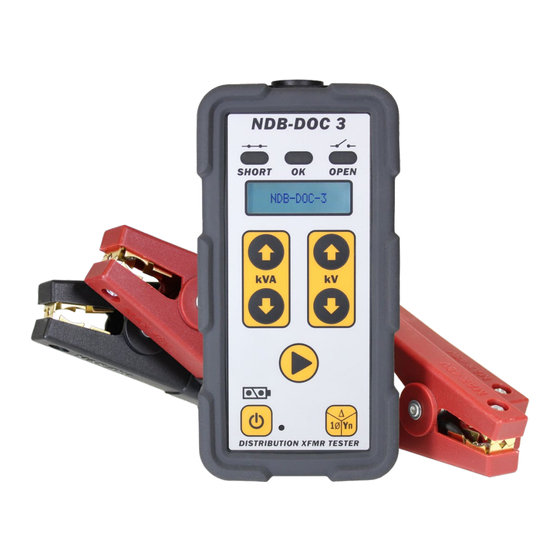
N D B - D O C - 3 U s e r M a n u a l 4. Application The NDB-DOC-3 is a test instrument designed to measure the status of de-ener- gized distribution transformers. It determines the presence of short circuits or open circuits in the transformer primary winding and also short circuits on the second- ary winding. The NDB-DOC-3 uses DC resistance and AC impedance test methods to test a wide range of distribution transformer configurations. The NDB-DOC-3 is designed to be operated without needing to disconnect the transformer secondary windings from their loads. Please note, partial shorts, or short shorts that only ap- pear under high voltages may not always be detected by the NDB-DOC-3. If used on secondary winding to perform an open winding test, user must stand clear of the primary high voltage terminals while testing. 5. Overview This section of the user manual describe the principal features of the NDB-DOC-3. Test lead connector Result indicator for: • Short circuit • OK circuit Display •... -
Page 7: Operation
N D B - D O C - 3 U s e r M a n u a l 6. Operation This section of the user manual describe how to operate the NDB-DOC-3. 6.1 Cable check test Perform a cable check test prior to test any power transformer to ensure test equipment’s integrity. -
Page 8: Single Phase Transformer Test
N D B - D O C - 3 U s e r M a n u a l 6.2 Single phase transformer test Use the NDB-DOC-3 on de-energized transformers only. 1. Press the power button to turn on the instrument. 2. Connect the test lead to the instrument. 3. Press the winding type selection button to select Single. 4. Press the kVA arrows to select the transformer size. 5. Press the kV arrows to select the transformer’s primary winding nominal voltage. 6. Connect the H1 clamp to the transformer’s H1 terminal. - Page 9 N D B - D O C - 3 U s e r M a n u a l 9. The test sequence will start and normally last for a few seconds. In some cases, the test will last up to 2 minutes. 10. Once the test is completed, the NDB-DOC-3 will display the result: • SHORT: The NDB-DOC-3 detected a short circuit either on the primary or secondary winding of the transformer. The SHORT red indicator will turn on. • OPEN: The NDB-DOC-3 detected an open circuit. The OPEN yellow indi- cator will turn on. The transformer's primary winding may have an open circuit, or the test clamps may have poor electrical connections. In cases where high DC resistance is measured, the test will last up to 2 minutes and the transformer will be considered open. • OK: The OK green indicator will turn on. The transformer’s DC resistance and AC impedance measured are within range. The transformer is con- sidered in good condition. Good condition Short circuit...
-
Page 10: Three Phase Transformer Test
N D B - D O C - 3 U s e r M a n u a l 6.3 Three phase transformer test Use the NDB-DOC-3 on de-energized transformers only. 1. Press the power button to turn on the instrument. 2. Connect the test lead to the instrument. 3. Press the winding type selection button to select the transformer’s pri- mary winding configuration type, either Delta or Yn. 4. Press the kVA arrows keys to select transformer size. 5. Press the kV arrows keys to select the transformer’s primary winding nom- inal voltage. 6. Connect the four clamps to the transformer: •... - Page 11 The secondary leads and load do not alter test result. • Connect N/GND clamp to the transformer neutral or ground. In Del- ta applications, simply connect the Neutral/ground clamp to a con- ductive point on the transformer casing (example: chassis ground wire) to enable the phase to chassis short-circuit detection. 7. Press the start button 8. The test sequence will start and normally last for a few seconds. In some cases, the test will last up to 2 minutes. 9. Once the test is completed, the NDB-DOC-3 will display the result: • SHORT: The NDB-DOC-3 detected a short circuit either on the primary or secondary winding of the transformer. The SHORT red indicator will turn on. • OPEN: The NDB-DOC-3 detected an open circuit. The OPEN yellow indi- cator will turn on. The transformer's primary winding may have an open circuit, or the test clamps may have poor electrical connections. Import- ant note: Detection of single winding open condition in a 3 phase delta transformer is not possible with the NDB-DOC-3.
-
Page 12: Delta Transformer Bank Test
N D B - D O C - 3 U s e r M a n u a l 6.4 Delta Transformer bank test Use the NDB-DOC-3 on de-energized transformers only. 1. Turn on the instrument by pressing the power button 2. Connect the test lead to the instrument. 3. Press the winding type selection button to select delta transformer’s primary winding. 4. Press the kVA arrows keys to select the transformer size. 5. Press the kV arrows keys to select the transformer’s pri- mary winding nominal voltage. 6. Connect the four clamps to the transformer: •... - Page 13 U s e r M a n u a l Tip: The secondary leads can stay connected to the transformers while testing. The secondary leads and load do not alter test result. The test sequence will start and normally last for a few seconds. In some cases, the test will last up to 2 minutes. 9. Once the test is completed, the NDB-DOC-3 will display the result: • SHORT: The NDB-DOC-3 detected a short circuit either on the primary or secondary winding of the transformer. The SHORT red indicator will turn on. •...
-
Page 14: Yn Transformer Bank Test
N D B - D O C - 3 U s e r M a n u a l 6.5 Yn Transformer bank test Use the NDB-DOC-3 on de-energized transformers only. 1. Turn on the instrument by pressing the power button 2. Connect the test lead to the instrument. 3. Press the winding type selection button to select Yn transformer’s primary winding. 4. Press the kVA arrows keys to select the transformer size. 5. Press the kV arrows keys to select the transformer’s pri- mary winding nominal voltage. 6. Connect the four clamps to the transformer: •... - Page 15 U s e r M a n u a l Tip: The secondary leads can stay connected to the transformers while testing. The secondary leads and load do not alter test result. The test sequence will start and normally last for a few seconds. In some cases, the test will last up to 2 minutes. 9. Once the test is completed, the NDB-DOC-3 will display the result: • SHORT: The NDB-DOC-3 detected a short circuit either on the primary or secondary winding of the transformer. The SHORT red indicator will turn on. •...
-
Page 16: Additional Information
N D B - D O C - 3 U s e r M a n u a l 7. Additional Information 7.1 Single phase transformer With the single phase transformer alone, configure the nominal voltage of the high side winding of this transformer. For example (name plate picture below) a 24940GRNY/14400V, rated at 25 kVA. We would enter 14kV and 25kVA. The 24940V marking on the name plate re- fers to when this transformer is used inside a 3 phase Yn... -
Page 17: Three Phase Banks
Basically this tells you that the transformer can be used in a 3 phase, grounded, Wye (Yn) con- figuration where the Line-Line (system Voltage) would be 4160V. But if you where to use this same single phase transformer in a Delta bank configuration then it would be used on a 2400V system. Using the NDB-DOC-3 with transformer banks we use the primary system voltages. Using the name plate in the picture above: • In a delta bank configuration example above, we would enter: 2kV and 225kVA (3 x 75kVA). Our test leads would connect to the de-energised bushings of the transformer bank: H1 test lead to H1 bushing of the of first transformer, H2 test lead to H1 bushing of the 2nd transformer and H3 test lead to the H1 bushing of the 3rd transformer. •... -
Page 18: Battery Replacement
N D B - D O C - 3 U s e r M a n u a l 8. Battery replacement The low battery indicator will turn on (red) when the battery level is critically low. To replace the batteries, simply remove the rubber protective case, slide the battery cover and carefully remove the depleted batteries. Install a fresh set of four batter- ies. Refer to technical specifications for more information.
Need help?
Do you have a question about the NDB-DOC-3 and is the answer not in the manual?
Questions and answers
Quem vende este aparelho em Portugal