
Subscribe to Our Youtube Channel
Related Manuals for howen MDVR-ME Series

Summary of Contents for howen MDVR-ME Series
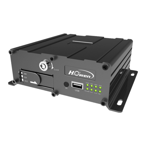
- Page 1 User Manual MDVR-ME Series(Hero-ME40-04/ME41-04/ME3 2-04/ME31-08 Series) Howen Technologies,LTD 2018-2019...
-
Page 2: Table Of Contents
Content 1. Overview................................3 2. Cautions................................3 2.1. Installation Environment..........................3 2.2. Avoid electric shock and fire........................3 2.3. Transport and operation.......................... 3 3. Product introduction............................3 4. Product Specification............................4 5. Mainframe................................4 5.1. Interface..............................4 5.2. Front panel..............................6 5.3. Rear panel..............................6 5.4. -
Page 3: Overview
Overview This manual is the instruction manual for ME series MDVR as below: (Hero-ME41-04, Hero-ME31-04,Hero-ME31-08,Hero-ME40-04 ect) Please read the manual before you using the product. The manual will be updated from time to time without prior notice. Cautions 2.1. Installation Environment 1. -
Page 4: Product Specification
Data self-protection, save data when shut down abnormally Product Specification 8V~36V, Check the supply voltage of the vehicle +8V ~ +36V battery before use; If it is supplied with more than Power input 36V for a prolonged period, the device may be damaged. - Page 5 Hero-ME40-04 Attention :Hero-ME40-04 without 3G and WIFI function, so it need not to set the parameters in the menu of 10.2.4 Network setting. HDD type MDVR: Hero-ME31-08...
-
Page 6: Front Panel
5.2. Front panel Interface Name Description Infrared Receiver 2.5 inch SATA HDD slot. Please unlock the lock with the key. HDD Slot You can also see SD card slot and SIM card slot with HDD slot together. SD card/SIM SIM card slot; card slot SD Card slot;... -
Page 7: Pin Definition Of Audio/Video Input/Output Port
3G/4G LTE Connect with 3G/4G LTE antenna. Connect with GPS antenna. WIFI Connect with WIFI antenna. Power Connect with power adapter/battery Connect with network cable for network For IO cables; I/O&Serial Including sensor input,sensor output,DC power output, RS232, RS485, sensor Extend Extension for I/O&Serial 5.4. -
Page 8: Pin Definition Of Io&Serial Port On 4Ch Mdvr
The port contains below interfaces: DC5V OUT; RS232; Sensor Input; Sensor Output; RS232-RX2 RS232-RX1 SENSOR-OUT SENSOR-IN4 SENSOR-IN2 VCC-5V RS232-TX2 RS232-TX1 GND SENSOR-IN3 SENSOR-IN1 5.6. Pin definition of IO&Serial port on 4CH MDVR The port contains below interfaces: DC12V OUT; DC5V OUT; RS232;... -
Page 9: Pin Definition Of Io&Serial Port On 8Ch Mdvr
5.7. Pin definition of IO&Serial port on 8ch MDVR Hero-ME31-08 IO&Serial The port contains below interfaces: DC12V OUT; DC5V OUT; RS232; RS485; Sensor Input; Sensor Output; VCC5V- RS232- RS232- SENSOR SENSOR SENSOR SENSOR SENSOR SNESOR SENSOR SENSOR -IN-8 -IN-7 -IN-6 -IN-5 -IN-4 -IN-3... -
Page 10: Remote Controller
5.8. Remote controller When the recorder is set with a password, press the Login key to input Login your password. As the system is not provided with recover and reset features, always keep your password in mind. INFO Short-cut for check the device’s information. On the monitoring interface, used to switch between quad view and single Quad View key view;... -
Page 11: Device And Installation
REW key Rewind key in four grades: 2X,4X,8X,16X NEXT key Page down or roll to the next file. PREV key Page up or roll to the previous file. Auto, preset, call, zoom +, zoom -, focus +, focus -, aperture +, aperture -, PTZ key PTZ, PRESET, RECALL, BRUSH. -
Page 12: Connect Power With Mdvr
6.Connect power with MDVR Use DC12V, 3A(at least) or higher(5A is better) power adapter in office test. As for vehicle installation, please connect ACC cable with ignition on vehicle. 7. Connect TFT monitor Connect a TFT monitor with AVOUT port on the rear panel of MDVR. Attention:The MDVR will provide power and image to TFT screen by Avout port, so don’t connect any external power for the TFT screen, or else, it will destroy the MDVR. -
Page 13: Menu Structure
For Hero-ME40-04,the structure is simple .It is only for recording on the device ,without the network (3G/4G, WIFI) , so it will not transmit the data to server .You can play on the device directly or by MDVR player(get the map information and video) . Menu structure System operations 9.1. -
Page 14: Main Menu
The default admin password for ME41-04,ME32-04 is 111111. With remote: Press 【LOGIN】button to login MDVR. Press【Enter】button to call the keyboard page to input password. If any err while inputting ,press【Delete】button to delete. With USB mouse: Please connect a USB mouse with MDVR to setup the menu. Right click on the live video interface and you can see the login page. -
Page 15: Search
9.2.1. Search Searching menu includes: video search, log search and image search. 9.2.1.1. Video Searching Date:Press number keys on remote to select the date, it defaults for the current day. - Page 16 Start time:Press number keys to input the time, it defaults for 00:00. End time:press number keys to input the time, it defaults for 23:59. Video Type:press 【Enter】to select: REC-ALL (all type of videos) REC- ALM(alarm videos) contains IO( I/O recording), G sensor, Speed ,Move, Fatigue,OCC type. Need set in the Alarm menu first. Disk Type:press【Enter】to select: main disk / mirror disk / disk backup.
-
Page 17: Log Search
Export: Press【Enter】, the selected videos will be exported to an external USB storage device . Note: If the selected period there is no video file and interface prompt: "! This day has no video file’’ 9.2.1.2. Log search Log management record : power on/off, GPS timing, alarm event information, including event date, event time, and event name. -
Page 18: System Setting
Search Date: Press number keys to enter the date, default is today. Start Time: Press the number keys to enter the time, default is 00:00. End time: Press the number keys to enter the time, default is 23:59. Search: Press【Enter】to select, search the log information from the start time to the end time. Press the arrow keys to select "First", "Previous", "Next", "Last", press key to display 【Enter】... -
Page 19: Register Info
9.2.2.1. Register info The CMS server will monitor and manage the vehicle by Device ID. Device ID、Plate No., Province ID, Terminal Model, Factor ID, Terminal ID, City ID:Press number keys to input. Device ID Set a number(12 digital at most) ,but must be unique, It’s very important , since we will add this device to the server by these numbers. -
Page 20: Time Setup
The administrator can set or change the parameters, so if you need to set some parameters, login with this account. The user can search and view the files only. OFF: Without password. When entering the menu, get into the main menu directly . 9.2.2.3. -
Page 21: Startup
9.2.2.4. Startup 4-channel 8-channel Power Mode:To set Power ON/Off mode, press【Enter】to select. Acc mode / timing mode. Timing mode: on/off according to the user’s setting period. Acc mode: On/off by the vehicle’s ACC ignition. Auto Reboot: ON/OFF. The default is OFF. If it’s ON, it will reboot at the Reboot Time. If the device is running all the 24 hours, please set it ON. -
Page 22: Config
9.2.2.5. Config Parameters import: Import configuration information in the USB driver to the current device. Parameters Export: Export all the configuration information of the current device to the USB flash driver.If there is no USB flash driver, it will saved in the existed HDD/SD card. Tips: If you had set the whole parameters in one device already, you can export it first, and then import to other devices by this function. -
Page 23: Record
you can check on the PC. For example, if you need more space for saving alarm videos and upload to FTP server, should change it . Just input a new value in StdPart(GB) and SAVE it. Block(MB): All videos are saving by block read&write technology. It’s not recording by time length. -
Page 24: Main Stream
The General info contains the basic setting for camera. When you install the MDVR, please double-check these sub-menu . TV System: Press【Enter】to select: PAL / NTSC, default is PAL. If it’s wrong ,the image will become Select PAL/NTSC according to the camera’s video type. Device will black-white color only. - Page 25 Enable: Press【Enter】to select: On / Off. Res: Resolution ,press【Enter】to select: D1 / HD1 / CIF / 720P. CIF:352*288,HD1:352*576, D1:704*576, 720P:1280*720 . FPS: Frames per second , More frames, every picture will be more clear. press【Enter】to select: 1-25 . NTSC : 30FPS , PAL: 25FPS. QUA: Quality of the video, press【Enter】to select: 1-8.
-
Page 26: Sub Stream
Storage Calculation MDVR support dual streams. Main stream is mainly used for local recording; Sub-stream is mainly used for network transmit. Main stream: Image Resolution Quality Level 1080P 8192 7168 6144 5120 4096 3072 2048 1536 720P 4096 3584 3072 2560 2048 1536 1024 800 Bitrate 2048 1536 1230 1024 900 [Kbps]... -
Page 27: Timed Recording
The sub-stream is used for live streaming. The higher Resolution, bit rate and frame rate, video will be more clearer, but need more 3G/4G data. Notice: 1. Currently 3G networks only support CIF real-time network transmission, the default setting is CIF and fixed. -
Page 28: Storage Setting
9.2.3.5. Storage setting Alarm Previous Rec: Set the previous recording time before the alarm happens. Press number keys to enter, 0 to 60 seconds for selection. Alarm delay:Set the delay recording time after the alarm happened. Press number keys to enter, 0 to 3600 seconds for selection. -
Page 29: Osd Set
9.2.3.6. OSD Set Set the stamp information on the image , and location to be displayed on the image. Time: Press【Enter】 to select Enable: on / off, press number keys to enter the X and Y coordinates. Plate: Press【Enter】 to select Enable: on / off, press number keys to enter the X and Y coordinates. GPS: Press 【Enter】... - Page 30 Protocol: It’s the protocol used to connect the center server. For server1 protocol: T-protocol is default setting .Don’t change it! For server2 protocol : It contains H-protocol ,R-protocol, Transpt, etc. .H-protocol is Howen protocol (our own protocol) if you need to link the third party FMS platform.
-
Page 31: Local Network Setup
9.2.4.2. Local Network Setup Local network IP LAN is used for local connection or IPC connect. The device supports LAN connect directly like as your PC. Set the same IP segment with your PC ’s address(include IP, Mask, Gate, DNS address. For MAC, just use our default setting address,don’t change), otherwise, it can not be connected. -
Page 32: Wifi Settings
Center No. : Default setting is *99#. Please inquiry your supplier if any change. User name, Password: set up a 3G/4G service user name and password. Also should inquiry your SIM card supplier! 9.2.4.4. WiFi settings WIFI Enabled: Press【Enter】to select: On / Off. Enable Encryption: Press【Enter】to select: On / Off. -
Page 33: Alarm
9.2.5. Alarm Alarms include: I/O alarm, speed alarm, G-sensor, motion detection, alarm voltage, Fatigue,serial port and PTZ control management. 9.2.5.1. IO Alarm (ME40-04 supports 4 I/O ports only) IN1-IN6 is for generally use (same with the I/O serials cable ), IN7 and IN8 are for iButton, it must be (on I/O serials cable , it is IN7 and IN9) status if you don’t use them. -
Page 34: Speed Alarm
Wait: The waiting time for trigger in case of mistaken touch. Record: Press【Enter】 to select: On / Off, enable when the alarm happens, it will record or not. Linkage: Press【Enter】to select: OFF/Output 1 / Output 2 / Buzzer/snap-up. Output1:Output1 cable will output a DC12V voltage when alarm is triggered. Output2:Output2 cable will output a DC12V voltage when alarm is triggered. -
Page 35: Acceleration
It contains Parking(parking time setting), L-Warn(low-speed warning), L-ALM(low-speed alarm), H-Warn(high-speed warning), H-ALM(high-speed alarm), Spd Up(speed up) ,Spd Down(speed down) these seven items. Set the parameters refer to the following text. When it break the rule ,it will trigger an alarm. For example , L-ALM(low-speed alarm), set it ON and the Limit value and other settings. -
Page 36: Motion Detection
The acceleration alarm first need to get coordinate correction, the vehicle may be parked on level ground to clear calibration. Tilt: it refers to a device rollover angle, unit is degree. Enable:Press【Enter】to select: ON/OFF. Limit: Set a limited value for system judgement.Press the number keys to enter. Wait : The waiting time in case of mistaken judgement . -
Page 37: Voltage Alarm
Enable:Press【Enter】 select: ON/MOVE/OCC. Limit: Set the threshold of video area/detection area percentage . Suggest 45. Sense: Sensitivity , it decides the detection sensitivity level .Press【Enter】 to select: 1-8. 1 is the highest level. Suggest to use 3. Record: Turn on/off recording function.Press【Enter】to select: On / Off. Alarm linkage: Press【Enter】to select: OFF/Output 1 / Output 2 / Buzzer/snap-up. -
Page 38: Ptz Control
Com port means the RS232 and RS485 communication ports, it’s used for connecting the accessory, such as fuel level detection, IC card reader, fatigue driving camera, people counting etc. For 4-channel device, COM1 & COM3 is RS232 ,COM2 & COM4 is RS485; For ME40-04, it supports RS232 only . -
Page 39: Fatigue Driving
It’s used for setting the PTZ device when control a PTZ camera(Press the PTZ button on the remote, then press + /- button). Protocol type: Pelco-D/Pelco-P for option. Address code: Set a different address code for each channel, the MDVR will recognize this address and control it. - Page 40 The important information as following: MCU version : CPU firmware version APP Version: The current firmware version. System power: The device current operation voltage. Phone NO.: Device ID actually. I/O status:Check the I/O electrical level status.1 is high, 0(lower than 3V) is low. You can check after device had connected an I/O device, such as, a panic button.
- Page 41 3G/4G: Module Type :WCDMA/FDD-LTE/TD-LTE SIM Signal:Signal intensity. SIM status:If there is no SIM card or the system have not detected the SIM card, it will show Not exist. Dial status: Dial Fail or success. Dial IP: If dial success, it will show the dial IP address. If failed, you should check the 10.2.4.3 Dial setting.
Need help?
Do you have a question about the MDVR-ME Series and is the answer not in the manual?
Questions and answers