
Subscribe to Our Youtube Channel
Related Manuals for Austdac SILBUS-TX4A(G)


Summary of Contents for Austdac SILBUS-TX4A(G)
- Page 1 Title 4 CHANNEL ANALOGUE TRANSMITTER TYPE SILBUS-TX4A(G) USER'S MANUAL Document Number 120-188-12 Issue...
-
Page 2: Revision Control
Fax: +1 412 635 0179 Copyright 2018 This document remains the property of Austdac Pty. Ltd. It is subject to its recall and must not be reproduced in part or whole or its contents divulged to third parties without prior written approval... -
Page 3: Table Of Contents
TABLE OF CONTENTS REVISION CONTROL ........................2 TABLE OF CONTENTS ........................3 PHOTOGRAPHS ..........................4 TABLES ............................4 FIGURES ............................4 1 GENERAL DESCRIPTION ......................5 2 WARNINGS AND PRECAUTIONS ....................5 2.1 USER ACCESS ........................6 2.2 STORAGE, INSTALLATION, USE AND MAINTAINANCE REQUIREMENTS ....... 6 2.2.1 Storage........................... -
Page 4: Photographs
PHOTOGRAPHS Photograph 1 SILBUS-TX4A front panel ..................7 Photograph 2 Access to console port and programming switch ............8 Photograph 3 Laptop connected to console port via MEAN1 interface .......... 11 Photograph 4 Hyper Terminal delay setup ..................24 TABLES Table 1 Status LED flash sequence meanings ................ -
Page 5: General Description
The four channel analogue transmitter is part of a family of explosion protected DIN rail mounting modules that transmit to and receive from an Austdac SILBUS field bus network. The SILBUS-TX4A(G) can transmit up to four 4-20mA or 0.4-2.0V analogue signals on four independent valid SILBUS channels. -
Page 6: User Access
EARTH 2.1 USER ACCESS There are no user serviceable parts within the SILBUS-TX4A(G). The user should not open or disassemble the SILBUS-TX4A(G). 2.2 STORAGE, INSTALLATION, USE AND MAINTAINANCE REQUIREMENTS The SILBUS-TX4A(G) should only be installed, operated and maintained by qualified personnel in accordance with the condition of safe use as outlined in the certificate. -
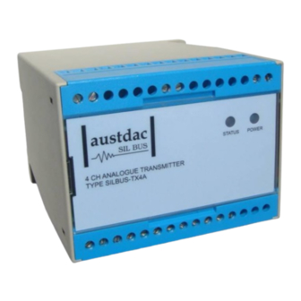
Page 7: Front Panel Layout
3 FRONT PANEL LAYOUT The four channel analogue transmitter front panel is located between the terminal blocks that form part of the enclosure. The front panel is shown in photograph 1 below. Photograph 1 SILBUS-TX4A front panel Located in the top right hand corner of the front panel are the STATUS and POWER indication LED’s. -
Page 8: Theory Of Operation
(Fastlink) or eight bit (Analink) value ready for transmission on the configured SILBUS channel. The transmission protocol can be independently selected for each analogue input. See Austdac document 120-009-10 for a more detailed description of SILBUS communications. -
Page 9: Operating Instructions
fault is generated. This fault can be transmitted as a digital signal on any valid configurable SILBUS channel address. Each analogue input is also compared with up to five configurable rising or falling set points. If the analogue input signal passes a set point level a digital alarm will be generated. This alarm can be configured to transmit on any valid SILBUS channel address. -
Page 10: Configuration
To use the console port an Austdac MEAN1 interface, A to B USB cable and laptop computer running Hyper Terminal are required. -
Page 11: Console Port Operation
6.1 CONSOLE PORT OPERATION The console port should be connected to a laptop running a terminal emulation program such as Hyper Terminal via the Austdac interface type MEAN1 and a USB cable as shown in the following photograph. Photograph 3 Laptop connected to console port via MEAN1 interface... -
Page 12: Repeat Command
TX4A::>HELP Software 2V01 0x07B9 Configuration 0x50E8 SN:00000000 Commands: -------------------------------------------------------------------------------- ********** Level 1: Standard Menu ********** HELP [1…7] Level of Help Displays Help Menu REPEAT [LF] [Refresh rate in seconds] Repeats Previous Command Firmware Version and Checksum STACK Displays Peak Stack Usage SBMAP Displays SILBUS I/O Map SBSTAT... -
Page 13: Version Command
Stack usage/size = 312/1024 Percentage Used = 30% TX4A::>_ This command would typically only be used when requested by an Austdac software engineer. 6.6 SILBUS MAP COMMAND The SILBUS map command allows the operator to obtain a snapshot of the SILBUS network to which the transmitter is connected. -
Page 14: Silbus Status Command
OFF channel. An example of an SBMAP is shown below with channels A4, P7 and P8 on or active: TX4A::>SBMAP ABCDEFGHIJKLMNOP 0000000000000000 0000000000000000 0000000000000000 1000000000000000 0000000000000000 0000000000000000 0000000000000001 0000000000000001 TX4A::>_ The SBMAP command is particularly useful when used with the repeat command as this will display a continuously updated table. -
Page 15: Analogue Input Address Command
TX4A::>_ 6.9 ANALOGUE INPUT ADDRESS COMMAND This command is used to display and configure the SILBUS channel addresses of the four analogue inputs of the SILBUS-TX4A. The current SILBUS channels can be displayed by simply entering the command name as shown in the example below: TX4A::>SBADDR ... -
Page 16: Fault Level Command
analogue input falls below a preconfigured fault level. The current SILBUS channels of the fault signals can be displayed by simply entering the command name as shown in the example below: TX4A::>SBFALT Under Level Fault Silbus Addresses are: Input [1] Fault Address = J2 Input [2] Fault Address = A6 Input [3] Fault Address = A7 Input [4] Fault Address = B3... -
Page 17: Trip Point Add Command
4 to 20mA signal. The current fault levels can be displayed by simply entering the command name as shown in the example below: TX4A::>FLTLEV Input [1] = 3.99mA Input [2] = 4.00mA Input [3] = 3.90mA Input [4] = 3.85mA If the command name is entered with additional attributes the fault levels can be configured to any valid level. -
Page 18: Set Point Delete Command
added to the configuration up to the upper limit of five set points per input channel. There is no restriction on the SILBUS addresses; they do not have to be in numerical order or from the same group. An example of adding a new set point to input 2 is shown below: TX4A::>ADDPT SET 2 H2 R 6.3 ... -
Page 19: Hysteresis Command
TX4A::>_ The use of the set point delete command without any attributes does not delete any set points. TX4A::>DELPT SET 1 3 Analog Input 1 1: G1 Trips on rising edge at 14.0mA 2: G2 Trips on rising edge at 15.1mA 3: G8 Trips on rising edge at 17.3mA 4: !G3 Trips on rising edge at 18.0mA Analog Input 2... -
Page 20: Analogue Select Command
hysteresis value is common to all four analogue inputs, faults and set points. The current hysteresis value can be displayed by simply entering the command name as shown in the example below: TX4A::>HYST Hysteresis level 0.10mA TX4A::>_ If the command name is entered with additional attributes the hysteresis level can be configured to any valid level. -
Page 21: Analogue Input Command
Once a valid marker address has been configured the error message will disappear as shown in the example below. TX4A::>ANASEL Chan[1] = Fastlink Chan[2] = Analink Chan[3] = Analink Chan[4] = Analink TX4A::>_ 6.16 ANALOGUE INPUT COMMAND The analogue select command is used to display the current value of the selected analogue input. -
Page 22: Upload Configuration Command
The following table may be used to record the configuration of the SILBUS-TX4A four channel analogue transmitter. 6.18 UPLOAD CONFIGURATION COMMAND The upload configuration command is used to extract the configuration profile of the SILBUS-TX4A via the MEAN1 interface and record it in a file on a PC. Having an exact copy of the configuration is useful for record keeping and future cloning of new SILBUS- TX4A transmitters for maintenance or system expansion. -
Page 23: Download Configuration Command
Austdac is planning to release a complete tool to allow direct upload, download and editing of the configuration profile. -
Page 24: Photograph 4 Hyper Terminal Delay Setup
Photograph 4 Hyper Terminal delay setup The terminal emulation program should be set up to allow a 100mS wait period after the carriage return at the end of each line during a download, this gives the target time to process the incoming data. SILBUS-TX4A(G) CONFIGURATION RECORD LOCATION SILBUS NETWORK... -
Page 25: Terminations And Connections
7 TERMINATIONS AND CONNECTIONS All connections to the four channel analogue transmitter are via cage-clamp terminals around the perimeter and near the front of the DIN rail mounting enclosure, these terminals can accommodate up to 4mm conductors. There are 16 possible connections to the transmitter;... -
Page 26: Power Input Port
When a link is placed between the ‘HI’ and ‘I to V’ terminals of an input it is converted to a current type input with a 100Ω current to voltage conversion resistor across the input. This resistor will convert 4-20mA signals to 0.4-2.0V signals at the ‘HI’ and ‘LO’ terminals. The analogue inputs are galvanically isolated from the SILBUS network port;... -
Page 27: Silbus-Tx4Ag Variant
The analogue input terminals are separated from all other terminals by more than 50mm. The individual analogue input channels are separated from each other by more than 6mm. This certification allows the four channel analogue transmitter to be located wholly within the hazardous area and the connection of intrinsically safe circuits to its various ports. -
Page 28: Software Revision And Display
10 SOFTWARE REVISION AND DISPLAY The software version of the four channel analogue transmitter type SILBUS-TX4A will vary as its functionality is improved at the request of our customers. The software version is given in two parts, the major revision level and the minor revision level and is written in the following format: VERSION M.mm where M represents the major revision level and mm represents the minor... -
Page 29: Specifications
11 SPECIFICATIONS Name ..................4 Channel Analogue Transmitter Type......................SILBUS-TX4A(G) Number of analogue channels ....................4 Analogue input current signal range (TX4A) ............. 4 – 20mA Analogue input voltage signal range (TX4A) ............0.4 – 2.0V Analogue input current to voltage conversion resistance (TX4A) ......100Ω 0.1% Analogue input current signal range (TX4AG) ............. - Page 30 Humidity ................80% to temperatures up to 31C ..................decreasing linearly to 50%rH at 40C....................max 80% rH, non-condensing...
Need help?
Do you have a question about the SILBUS-TX4A(G) and is the answer not in the manual?
Questions and answers