
Related Manuals for Austdac SILBUS-TX1T


Summary of Contents for Austdac SILBUS-TX1T
- Page 1 Title 1 CHANNEL TEMPERATURE TRANSMITTER TYPE SILBUS-TX1T USER MANUAL Document Number 120-359-12 Issue...
-
Page 2: Revision Control
Fax: +1 412 635 0179 Copyright 2018 This document remains the property of Austdac Pty. Ltd. It is subject to its recall and must not be reproduced in part or whole or its contents divulged to third parties without prior written approval... -
Page 3: Table Of Contents
TABLE OF CONTENTS REVISION CONTROL ........................2 TABLE OF CONTENTS ........................3 PHOTOGRAPHS ..........................4 TABLES ............................4 FIGURES ............................4 1 GENERAL DESCRIPTION ......................5 2 WARNINGS AND PRECAUTIONS ....................5 2.1 USER ACCESS ........................6 2.2 STORAGE, INSTALLATION, USE AND MAINTAINANCE REQUIREMENTS ....... 6 2.2.1 Storage........................... -
Page 4: Photographs
Photograph 4 Hyper Terminal delay setup ..................20 Photograph 5 Typical 3 wire PT100 sensor ................... 22 TABLES Table 1 SILBUS-TX1T Temperature vs. Input voltage ..............9 Table 2 Status LED flash sequence meanings ................10 Table 3 SILBUS-TX1T Temperature ranges ................. 18 Table 4 SILBUS-TX1T Configuration record ................. -
Page 5: General Description
10, this pin is allocated for the return current of the PT100. If the SILBUS-TX1T is used in a manner not specified by Austdac then the protection provided by the SILBUS-TX1T may be impaired. PRECAUTIONS ... -
Page 6: User Access
DC SUPPLY EARTH 2.1 USER ACCESS There are no user serviceable parts within the SILBUS-TX1T. The user should not open or disassemble the SILBUS-TX1T. 2.2 STORAGE, INSTALLATION, USE AND MAINTAINANCE REQUIREMENTS The SILBUS-TX1T should only be installed, operated and maintained by qualified personnel in accordance with the condition of safe use as outlined in the certificate. -
Page 7: Front Panel Layout
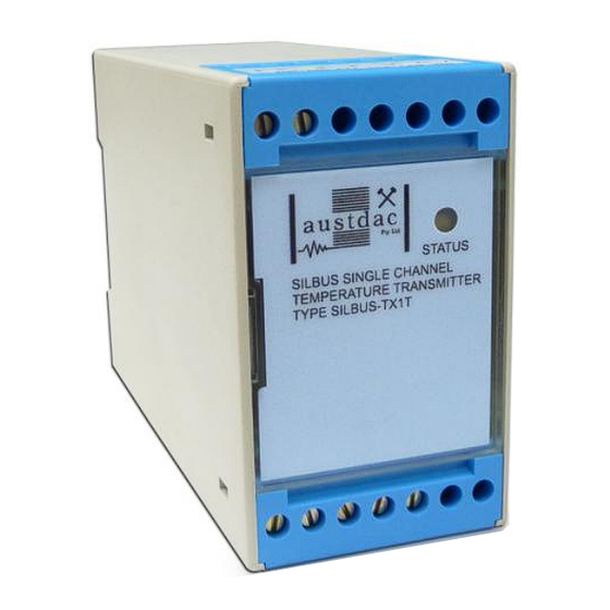
3 FRONT PANEL LAYOUT The SILBUS-TX1T front panel is located between the terminal blocks that form part of the enclosure. The front panel is shown in photograph 1 below. Photograph 1 SILBUS-TX1T front panel Located in the top right hand corner of the front panel is the yellow STATUS indication LED. -
Page 8: Theory Of Operation
The temperature input is converted to a sixteen bit (Fastlink) or eight bit (Analink) value ready for transmission on the configured SILBUS channel. The analogue transmission protocol can be configured for the temperature input. See Austdac document 120-009-10 for a more detailed description of SILBUS communications. -
Page 9: Table 1 Silbus-Tx1T Temperature Vs. Input Voltage
Figure 1 PT100 sensors and typical lead identifications The SILBUS-TX1T temperature transmitter functions by driving a constant current of 200uA out of terminal 8 through the PT100 sensor and back in through terminal 11. This current will cause a voltage to appear across the sensor proportional to the sensor temperature. -
Page 10: Operating Instructions
To use the console port an Austdac MEAN1 interface, A to B USB cable and laptop computer running Hyper Terminal or any other console program is required. -
Page 11: Console Port Operation
6.1 CONSOLE PORT OPERATION The console port should be connected to a laptop running a terminal emulation program such as Hyper Terminal via the Austdac interface type MEAN1 and a USB cable as shown in the following photograph. Photograph 3 Laptop connected to console port via MEAN1 interface... -
Page 12: Help Command
Note: The red "RUN/PROG" switch (see Photograph 2) next to the console port connector should be in the run position (pushed towards console port connector) at all times. When in "RUN" mode, for the console port to operate, the SILBUS network needs to be connected to the SILBUS port. -
Page 13: Version Command
TX1T::>REPEAT Temperature = 0.1degC In the above example, in this mode the repeat command writes over the previously displayed information. If required, the repeat command can be made to refresh the information on a new line by entering LF (line feed) as part of the command invocation. By default, the repeat command refreshes the display every one second. -
Page 14: Temperature Input Address Command
6.6 TEMPERATURE INPUT ADDRESS COMMAND This command is used to display and configure the SILBUS channel address of the temperature input of the SILBUS-TX1T. The current SILBUS channel can be displayed by simply entering the command name as shown in the example below: TX1T::>SBADDR ... -
Page 15: Analogue Protocol Select Command
This command is used to display and configure the SILBUS channel addresses, direction and level of the trip point alarms of the SILBUS-TX1T. The trip alarms are generated when the temperature input passes a preconfigured rising or falling trip point level. Up to... -
Page 16: Set Point Delete Command
five trip point alarms can be assigned to the temperature input. The current configuration of the set points can be displayed by simply entering the command name as shown in the example below: TX1T::>ADDPT No Limit Points TX1T::>_ The above example shows that no set points have been configured. If the command is entered with additional attributes more set points can be added to the configuration up to the upper limit of five set points. -
Page 17: Trip Set Point Hysteresis Command
TX1T::>DELPT SET 1 Setting Changed 1: J3 Trips on a falling edge at 65.1degC TX1T::>_ The above example shows the deletion of the first set point. The keyword “SET” is required to invoke the deletion. The number “1” specifies which set point to delete. Note that remaining set points are renumbered after execution of the delete command. -
Page 18: Range Command
The upload configuration command is used to extract the configuration profile of the SILBUS-TX1T via the MEAN1 interface and record it in a file on a PC. Having an exact copy of the configuration is useful for record keeping and future cloning of new SILBUS- TX1T transmitters for maintenance or system expansion. -
Page 19: Download Configuration Command
Austdac is planning to release a complete tool to allow direct upload, download and editing of the configuration profile. -
Page 20: Photograph 4 Hyper Terminal Delay Setup
Open the previously saved configuration file in Notepad or a similar non-word processing editor and highlight the configuration as shown below. CFGDWN S00300000FC S11300000000001001022E008056000105000000CF S113001080000000800000008000000080000000DC S11300208000140008001E00090028000A000000D7 S113003080000000800000006492000011002ED9AE S9030000FC Copy and paste the configuration from Notepad to the TX1T::> prompt in Hyper Terminal as shown below. -
Page 21: Terminations And Connections
The following table may be used to record the configuration of the SILBUS-TX1T single channel temperature transmitter. SILBUS-TX1T CONFIGURATION RECORD... -
Page 22: Temperature Input Port
The +SENSE terminal 9 is linked to the DRIVE terminal 8 for two wire PT100 sensors only. The –SENSE input is not implemented on the SILBUS-TX1T. Terminal 10 is only there to provide a place to terminate the –SENSE wire of a four wire sensor, no additional compensation is provided beyond that of a three wire sensor. -
Page 23: Certification
IECEx TSA 07.0002X, Ex ia I, as part of the Dupline / SILBUS system. The certification requires that the SILBUS-TX1T be mounted within a host enclosure that provides a minimum ingress protection of IP54 (IP55 for Queensland Australia). -
Page 24: Specifications
10 SPECIFICATIONS Name ............... Single Channel Temperature Transmitter Type........................SILBUS-TX1T Number of temperature channels ................... 1 Sensor type ................PT100 (2 wire, 3wire or 4wire) Temperature range ............-10 C to +100 C or -20 C to +200 Sensor drive current ....................... 200uA Temperature input transmission protocol .......... - Page 25 ....................max 80% rH, non-condensing...
Need help?
Do you have a question about the SILBUS-TX1T and is the answer not in the manual?
Questions and answers