Advertisement
Quick Links
PiHPSDR CONTROLLER ASSEMBLY MANUAL
Please note that you will have to create a bootable MicroSD card and install it in your Pi before
proceeding with the hardware assembly, it is assumed that you know how to do this, instructions are
available on the raspberripi.org website.
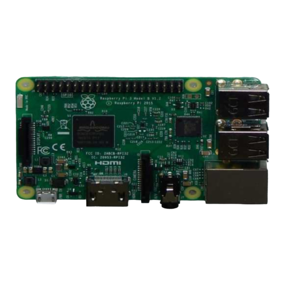
Contents of the Rpi and the official Rpi 7 inch screen kit
Please remove the two spacers as shown above and replace with the supplied screws
Advertisement

Summary of Contents for Apache Labs PiHPSDR
- Page 1 PiHPSDR CONTROLLER ASSEMBLY MANUAL Please note that you will have to create a bootable MicroSD card and install it in your Pi before proceeding with the hardware assembly, it is assumed that you know how to do this, instructions are available on the raspberripi.org website.
- Page 2 De solder the 5 pin header and solder the 5 pin ribbon cable as shown above Fix the two spacers removed earlier from the Screen PCB and secure on to the Controller PCB with nuts (Supplied with the kit) as shown above...
- Page 3 Your 5 pin cable assembly should look like this once soldered There are four Philips head screws supplied with the kit...
- Page 4 Use the above screws to fix the screen on to the controller PCB, ensure orientation is as above...
- Page 5 Once the screen and the controller pcb are secured, place the Rpi on the four spacers and screw on the four screws supplied with the Rpi kit.
- Page 6 Now connect the Display flex cable as shown above to the Display PCB and the Pi...
- Page 7 Connect the 40pin IDC cable to the controller PCB and Pi observing polarity (red strip) as above...
- Page 8 Place the assembled Kit on the Controller back chassis as above an screw the Hex nuts...
- Page 9 Remove the plastic protection film from the display...
- Page 10 Place the top cover and screw on the front panel screws...
- Page 11 Place the E1/E2/E3 knobs on the encoders...
- Page 12 Ensure adequate spacing between the panel and knob since the knobs also function as push button switches Finally Secure the tuning knob...
- Page 13 Your kit is assembled, congratulations! Power it on using the supplied cable and a 12v DC supply...
Need help?
Do you have a question about the PiHPSDR and is the answer not in the manual?
Questions and answers