
Subscribe to Our Youtube Channel
Related Manuals for Redback Networks SmartEdge 400

Summary of Contents for Redback Networks SmartEdge 400
- Page 1 SmartEdge 400 Router Hardware Guide Release 4.0.3 Part Number 220-0364-05 Corporate Headquarters Redback Networks Inc. 300 Holger Way San Jose, CA 95134-1362 http://www.redback.com Tel: +1 408 750 5000...
- Page 2 Redback and SmartEdge are trademarks registered at the U.S. Patent & Trademark Office and in other countries. AOS, NetOp, SMS, and User Intelligent Networks are trademarks or service marks of Redback Networks Inc. All other products or services mentioned are the trademarks, service marks, registered trademarks or registered service marks of their respective owners.
- Page 3 VCCI Class A Statement European Community Mark The marking on this product signifies that it meets all relevant European Union directives. Safety Notices Laser Equipment: CAUTION! Use of controls or adjustments of performance or procedures other than those specified herein may result in hazardous radiation exposure. Class 1 Laser Product—Product is certified by the manufacturer to comply with DHHS Rule 21 Subchapter J.
-
Page 5: Table Of Contents
SmartEdge 400 Chassis ........ - Page 6 Connect the Cables from the Rear of the Chassis ..........4-28 SmartEdge 400 Router Hardware Guide...
- Page 7 Chapter 5: Determining Operating Status ............5-1 Powering On the System .
- Page 8 Index ................... . 1 viii SmartEdge 400 Router Hardware Guide...
-
Page 9: About This Guide
Redback SmartEdge 400 router. Related Publications To ensure a complete and correct installation of a SmartEdge 400 router, we recommend that you read and use the documentation set in the following order: • SmartEdge 400 System Unpacking Instructions Provides information about unpacking the system and its components. -
Page 10: Intended Audience
• Chapter 5, “Determining Operating Status” Describes the SmartEdge 400 chassis and card LEDs used to determine the status of the system. It also describes how to troubleshoot hardware problems and use the on-demand diagnostics to isolate faults to the card level. -
Page 11: Conventions
Provides cable and connector specifications for all SmartEdge 400 cables and connectors. • Appendix B, “Alarms and Probable Causes” Provides tables of alarm conditions and probable causes for the SmartEdge 400 chassis and its cards. Conventions The conventions used for notes, cautions, and warnings provide special information in this guide: Note Provides related information for the topic described in the previous paragraph. -
Page 12: Ordering Documentation
2. On the Redback Networks Support web site, select one of the Redback Networks product line tabs at the bottom of the web page, click Documentation on the navigation bar, and then click To Order Books on the navigation bar. -
Page 13: Chapter 1: System Description
The SmartEdge 400 router is a carrier-class product with an architecture that supports packetized traffic. The SmartEdge 400 router can be used as an edge aggregation router to directly connect customers to the network and supports a variety of interfaces and vital services, such as quality of service (QoS) and inbound and outbound access control lists (ACLs). -
Page 14: General Specifications
• Alarms: audible and visual: critical, major, minor, ACO Note Protection for cards and ports is dependent on the release of the operating system. The SmartEdge 400 router supports a wide variety of interfaces, such as: • Synchronous Optical Network/Synchronous Digital Hierarchy (SONET/SDH) OC-3c/STM-1c, OC-12c/STM-4c, and OC-48c/STM-16c •... -
Page 15: Alarms
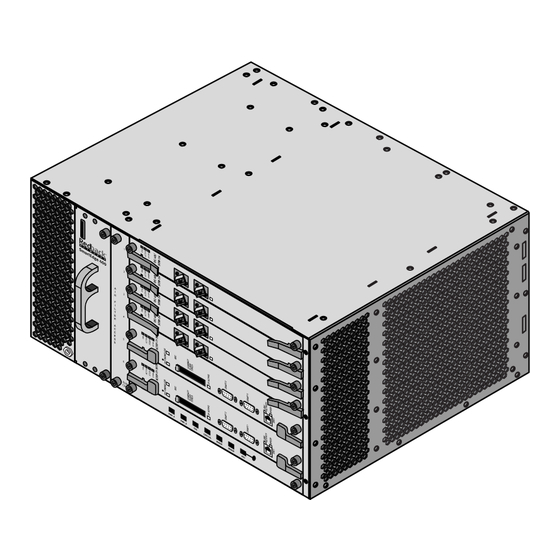
AC Power Tray SmartEdge 400 Chassis The SmartEdge 400 chassis has six slots with two slots dedicated to the controller cards and four slots available for a flexible combination of traffic cards. A separate area of the chassis has fans for forced-air cooling. -
Page 16: Controller Cards
To maintain the air flow through the chassis, empty slots have blank cards installed. Figure 1-1 shows the SmartEdge 400 chassis. Figure 1-1 SmartEdge 400 Chassis The rear of the chassis has connectors for power (A and B sides), DS-3 and E3 cards installed in slots 3 and 4, alarm outputs and status inputs, and dual external-timing inputs for synchronization. - Page 17 System Components Table 1-2 lists the differences between the XCRP and XCRP3 Controller cards. Table 1-2 Controller Card Comparison Feature XCRP XCRP3 Main memory 768 MB 768 or 1,280 MB NVRAM System image and file storage 192 or 256 MB 512 MB Real-time clock External timing implementation...
-
Page 18: Install A Mass-Storage Device
SmartEdge router. To reduce the risk, use only the internal compact-flash cards provided by Redback, and install only mass-storage devices purchased from Redback. These devices have been tested with the SmartEdge router. SmartEdge 400 Router Hardware Guide... -
Page 19: Management Workstation
System Components • Support for an external timing connection A controller card supports a BITS (DS-1) or SSU (E1) interface for external timing inputs. For the XCRP Controller cards, the type of interface is denoted in the label suffix on the card: “T1 BITS” for DS-1 and “E1 SSU”... - Page 20 • Fully redundant configuration — When two controller cards are installed in the SmartEdge 400 chassis, one functions as the active controller and the other card functions as the standby controller, providing full redundancy for high-reliability networking requirements. In the event of a controller card failure, the redundant card automatically becomes the active controller, thereby avoiding any unnecessary service disruption in the network.
-
Page 21: Traffic Cards
System Components Traffic Cards Table 1-4 lists the traffic cards supported on the SmartEdge 400 router; for more information about traffic cards, see Chapter 2, “Traffic Card Descriptions.” In the table, IR, LR, and SR abbreviations are used for Intermediate Reach, Long Reach, and Short Reach, respectively. -
Page 22: Ac Power Tray
A pair of LEDs on the front panel of each installed power supply indicate the status of the AC-input and DC-output power to and from the AC power tray. Each AC power supply connects to the SmartEdge 400 chassis with an AC power tray jumper cable using connectors on the rear of the AC power tray and provides sufficient power for a fully loaded chassis. -
Page 23: Chapter 2: Traffic Card Descriptions
C h a p t e r 2 Traffic Card Descriptions ® This chapter describes each of the traffic cards that are currently available for the SmartEdge 400 router. Note In the descriptions that follow, the term, controller card, refers to the Cross-Connect Route Processor (XCRP) or the XCRP Version 3 (XCRP3) Controller card, unless otherwise noted. - Page 24 – 12-port Channelized DS-3 1 to 6 Clear-Channel DS-3 1 to 6 Clear-Channel E3 – Channelized E1 1 to 12 Ethernet 10/100 Ethernet 1 to 6 FX-100 Ethernet – Gigabit Ethernet (any version) 1, 3 SmartEdge 400 Router Hardware Guide...
-
Page 25: Oc-48C/Stm-16C Long Reach Card
OC-48c/STM-16c Long Reach Card OC-48c/STM-16c Long Reach Card The OC-48c/STM-16c Long Reach (LR) card provides a single 2.4-Gbps SONET or SDH port, which is used as either an optical line or optical trunk interface. Figure 2-1 shows the front panel of the OC-48c/STM-16c LR card. - Page 26 4. Protection features for various types of cards and ports are dependent on the release of the operating system; the system supports a mix of protected and unprotected ports. 5. Measured 20 dB down from the central wavelength peak. SmartEdge 400 Router Hardware Guide...
-
Page 27: Oc-48C/Stm-16C Short Reach Card
OC-48c/STM-16c Short Reach Card OC-48c/STM-16c Short Reach Card The OC-48c/STM-16c Short Reach (SR) card provides a single 2.4-Gbps SONET or SDH port, which is used as either an optical line or optical trunk interface. Figure 2-2 shows the front panel of the OC-48c/STM-16c SR card. - Page 28 3. The SC connectors on the card are type SC/PC; cable and card connectors must match. 4. Protection features for various types of cards and ports are dependent on the release of the operating system; the system supports a mix of protected and unprotected ports. SmartEdge 400 Router Hardware Guide...
-
Page 29: Oc-12C/Stm-4C Intermediate Reach Card
OC-12c/STM-4c Intermediate Reach Card OC-12c/STM-4c Intermediate Reach Card The OC-12c/STM-4c Intermediate Reach (IR) card supports four SONET or SDH single-mode fiber (SMF) ports, each of which operates at 622 Mbps, and can be used either as an optical line or optical trunk interface. - Page 30 3. Loss budget is calculated using (minimum output power) – (minimum sensitivity). 4. Protection features for various types of cards and ports are dependent on the release of the operating system; the system supports a mix of protected and unprotected ports. SmartEdge 400 Router Hardware Guide...
-
Page 31: Oc-3C/Stm-1C Intermediate Reach Card
OC-3c/STM-1c Intermediate Reach Card OC-3c/STM-1c Intermediate Reach Card The OC-3c/STM-1c Intermediate Reach (IR) card supports eight SONET or SDH SMF ports, each of which operates at 155 Mbps and is used either as an optical line or optical trunk interface. Figure 2-4 shows the front panel of the OC-3c/STM-1c IR card. - Page 32 3. Loss budget is calculated using (minimum output power) – (minimum sensitivity). 4. Protection features for various types of cards and ports are dependent on the release of the operating system; the system supports a mix of protected and unprotected ports. 2-10 SmartEdge 400 Router Hardware Guide...
-
Page 33: Atm Oc-12C/Stm-4C Intermediate Reach Cards
ATM OC-12c/STM-4c Intermediate Reach Cards ATM OC-12c/STM-4c Intermediate Reach Cards The ATM OC-12c/STM-4c Intermediate Reach (IR) and the Enhanced ATM OC-12c/STM-4c IR cards each support one SONET or SDH SMF port, which operates at 622 Mbps, and can be used either as optical line or optical trunk interfaces. - Page 34 –28 dBm Overload level –8.0 dBm (minimum) 1. Each optical port has separate connectors for the transmit (TX) and receive (RX) circuits. 2. Loss budget is calculated using (minimum output power) – (minimum sensitivity). 2-12 SmartEdge 400 Router Hardware Guide...
-
Page 35: Atm Oc-3C/Stm-1C Intermediate Reach Cards
ATM OC-3c/STM-1c Intermediate Reach Cards ATM OC-3c/STM-1c Intermediate Reach Cards The ATM OC-3c/STM-1c Intermediate Reach (IR) cards support two or four SONET or SDH SMF ports, each of which operates at 155 Mbps, and can be used either as optical line or optical trunk interfaces. Figure 2-6 shows the front panels of the ATM OC-3c/STM-1c IR cards. - Page 36 1. Each optical port has separate connectors for the transmit (TX) and receive (RX) circuits. 2. Support for the low-density (2-port) version of the 4-port card is dependent on the release of the operating system. 3. Loss budget is calculated using (minimum output power) – (minimum sensitivity). 2-14 SmartEdge 400 Router Hardware Guide...
-
Page 37: Atm Ds-3 Card
ATM DS-3 Card ATM DS-3 Card The ATM DS-3 card supports 12 PDH ports, each of which operates at operates at 44.736 Mbps. Each port has two BNC connectors, located on the back of the SmartEdge chassis, for incoming and outgoing traffic. Incoming packet streams on the DS-3 ports are terminated, and the traffic is selectively routed or switched to its destination. - Page 38 0 to 349.0 ft (0 to 106.4m) or 349.0 to 450.0 ft (106.4 to 137.2m) Compliance Telcordia GR-499, ANSI T1.102, T1.107 1. Support for the low-density (6-port) version of the card is dependent on the release of the operating system. 2-16 SmartEdge 400 Router Hardware Guide...
-
Page 39: Channelized Oc-12 To Ds-N Intermediate Reach Cards
Channelized OC-12 to DS-n Intermediate Reach Cards Channelized OC-12 to DS-n Intermediate Reach Cards The Channelized OC-12 to DS-3 and OC-12 to DS-1 Intermediate Reach (IR) cards each support a single SONET SMF port, which operates at 622 Mbps. Figure 2-8 shows the front panels of the channelized OC-12 to DS-1 and channelized OC-12 to DS-3 IR cards. - Page 40 –28 dBm Overload level –8.0 dBm (minimum) 1. Each optical port has separate connectors for the transmit (TX) and receive (RX) circuits. 2. Loss budget is calculated using (minimum output power) – (minimum sensitivity). 2-18 SmartEdge 400 Router Hardware Guide...
-
Page 41: Channelized Stm-1 To E1 Intermediate Reach Card
Channelized STM-1 to E1 Intermediate Reach Card Channelized STM-1 to E1 Intermediate Reach Card The Channelized STM-1 to E1 Intermediate Reach (IR) card supports three SDH SMF ports, which operate at 155.52 Mbps and provide the means whereby incoming E1 channels can be selectively routed to various destinations in the network. - Page 42 1. Each optical port has separate connectors for the transmit (TX) and receive (RX) circuits. 2. Support for the low-density (1-port) version of the card is dependent on the release of the operating system. 3. Loss budget is calculated using (minimum output power) – (minimum sensitivity). 2-20 SmartEdge 400 Router Hardware Guide...
-
Page 43: Channelized And Clear-Channel Ds-3 Cards
Channelized and Clear-Channel DS-3 Cards Channelized and Clear-Channel DS-3 Cards The following versions of DS-3 cards are supported: • Channelized: 3-port and 12-port • Clear-channel: 12-port Each port has two BNC connectors, located at the rear of the SmartEdge chassis, for incoming and outgoing traffic, and operates at 44.736 Mbps. - Page 44 0 to 349.0 ft (0 to 106.4m) or 349.0 to 450.0 ft (106.4 to 137.2m) Compliance Telcordia GR-499, ANSI T1.102, T1.107 1. Support for the low-density (6-port) version of the card is dependent on the release of the operating system. 2-22 SmartEdge 400 Router Hardware Guide...
-
Page 45: Clear-Channel E3 Card
Clear-Channel E3 Card Clear-Channel E3 Card The Clear-Channel E3 card supports six ports; each port has two BNC connectors, located at the rear of the SmartEdge chassis, for incoming and outgoing traffic, and operates at 34.368 Mbps. Incoming packet streams are terminated, and the traffic is selectively routed or switched to its destination. Each port supports Cisco HDLC, Frame Relay, or PPP/HDLC encapsulation. - Page 46 AT&T type 734 or equivalent Protection (equipment) None Signal amplitude G.703 Cable length AT&T type 734 coaxial, or equivalent: 0 to 1,000.0 ft (0 to 304.8m) Compliance ITU-T G.703, ETS 300386-1, ETS 300386-2/EN 300386:2000, GR-1089-Core 2-24 SmartEdge 400 Router Hardware Guide...
-
Page 47: Channelized E1 Card
Channelized E1 Card Channelized E1 Card The Channelized E1 card provides 24 E1 ports, each of which operates at 2.048 Mbps, through a pair of SCSI-3 connectors located on the front panel. Each cable is connected to a patch panel. (The patch panel can be of any type;...
Need help?
Do you have a question about the SmartEdge 400 and is the answer not in the manual?
Questions and answers