Table of Contents
Advertisement
Quick Links
Advertisement
Table of Contents

Related Manuals for ASCEL Electronic AE20204


Summary of Contents for ASCEL Electronic AE20204
- Page 1 Æ20204 LC METER Assembly and Operation Manual...
- Page 2 REV 3.0 EN © 2014 Ascel Electronic...
-
Page 3: Table Of Contents
Table of Contents Safety Information..............ii Handover of a Device Built From a Kit........iv Intended Use................iv ESD Warning................v AE20204 LC METER..............1 Circuit Description..............2 Soldering..................5 Component Reference..............7 Assembly..................15 Troubleshooting Checklist............18 Power Supply................20 Case Mounting.................21 Operation..................22 Circuit Diagram...............25 Bill of Materials...............26 Component Placement.............28 Data Interface................29... -
Page 4: Safety Information
Warning Please read this manual before you assemble and use this kit. Keep it accessible for all users at all times. Safety Information Know and follow the applicable regulations for electric devices in your region. In Germany, these especially 0100, 0550/0551, VDE 0700, VDE 0711 and VDE 0860. - Page 5 •Always check if the device is suitable for the intended purpose before putting the unit in use. Seek assistance from a qualified professional or the manufacturer if you are not sure. • The manufacturer assumes no liability for errors made during assembly or operation.
-
Page 6: Handover Of A Device Built From A Kit
Handover of a Device Built From a Kit (in countries where applicable) If you hand over a device built from a kit, you legally become the manufacturer. This means you are responsible for complying with the appropriate regulations for electronic devices. -
Page 7: Esd Warning
ESD Warning What is ESD? ESD (Electrostatic Dis- charge) is the sudden flow of electricity between two Warning symbol for an objects caused by contact electrostatic sensitive device or an electrical short. It can reach very high voltages of many kV. In some cases even over 100kV! Causes of ESD The main cause of ESD events is static electricity. -
Page 8: Ae20204 Lc Meter
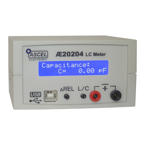
AE20204 LC METER The AE20204 LC Meter allows the measurement of capacitance inductance passive components, particularly very small values, even below 1 pF / 1 µH. The resolution thereby is 0.01 pF (10 fF) / 10 nH. It is an invaluable aid for amateur radio enthusiasts, as well as anyone engaged in electronics. -
Page 9: Circuit Description
Circuit Description To measure capacitance and inductance, the AE20204 LC Meter uses an oscillator composed of IC2, C7, C8, C9, L1, R2, R3, R4, R5 and R9. The tested capacitor is switched in parallel to C9 to measure capacitance. The tested inductor is switched in series to L1 to measure inductance. - Page 10 First, the frequency without C10 is measured (f1). √ 2⋅π⋅ L1⋅C9 Then, the frequency f2 is measured with C10. f2 = √ 2⋅π⋅ L1⋅ (C9+ 1000pF) C9 can be obtained by equalizing both equations. ⋅1000pF − f2 Since C9 is known now, L1 can be calculated. 4⋅π...
- Page 11 Note: the values of real capacitors and inductors are not constant, but depends (amongst others) on frequency. Measuring with different test frequencies will give different results! Note: electrolytic capacitors can not be measured with this device. Note: the quality factor of the inductor must be sufficient to allow oscillation on test frequency.
-
Page 12: Soldering
Soldering Please read the following pages if you are not yet experienced in soldering. Good soldering is a matter of practice! Practice on old boards until you feel confident before assembling the kit. • The parts are mounted on the silkscreen side of the PCB. Except parts whose designators ends with an asterisk (like S1*). - Page 13 • When soldering active components (ICs, Transistors, LEDs...), it is very important to prevent overheating the components. They should be soldered in no more than about 5 seconds. In addition, it is important not to confuse the polarity! See the next chapter on individual component types and their correct orientation.
-
Page 14: Component Reference
Component Reference 1 Resistors To save PCB space, the resistors are mounted standing. To install: 1. Bend the leads in form and put the resistor through the corresponding mounting holes. 2. Bend the leads aside to prevent the resistor from falling out. 3. - Page 15 Color Codes: Color Digit Multiplier Tolerance ± in % None Silver Gold Black Brown Orange Yellow Green Blue 0.25 Purple Grey 0.05 White 2 Capacitors / Electrolytic Capacitors Capacitors are soldered the same way as resistors. Electrolytic capacitors are polar. They must be mounted in the correct orientation! They will be destroyed when installed in reverse polarity and may even burst! Please keep in mind that different manufacturers mark the...
- Page 16 Capacitance Identification A three-digit number without letters is the capacitance in pF, where a are the first two digits calculated this way: a∗10 and b is the third digit (105 become 10*10 pF = 1µF). One- or two-digit numbers states the capacitance directly in pF. A number including the letter "n"...
- Page 17 3 Diodes The circular band on diodes identifies the cathode (negative terminal). The bar depicts the cathode in the symbol. The positive terminal is called the anode. Diodes are mounted horizontal. Try not to heat up the body of the diode while soldering. 4 LEDs LEDs (light-emitting diodes) must be soldered with respect to the correct polarity as well.
- Page 18 5 IC-Sockets / ICs With ICs (integrated circuits), it is essential to observe correct polarity. Most ICs will be damaged or destroyed when mounted incorrectly. The mark on the silkscreen must match the notch on top of the IC. Pin numbers are counted counter-clockwise, starting from the notch.
- Page 19 6 Transistors Transistors must be mounted in the correct orientation. The flat side of the transistor must match the correspondent side in the silkscreen drawing. The leads may not cross. Note: field-effect transistors (FETs) are extremely sensitive to ESD. 7 Crystal The polarity of the crystal is not relevant, but the bottom side of the package is conductive.
- Page 20 8 Inductors Inductors are soldered just like resistors. They also use similar color-coding, usually with four bands. The first two are the base value (see table below), the third is the multiplier to the base value and the fourth is the tolerance. The inductor value base value * multiplier [ ±...
- Page 21 9 Relays The side of the relay marked with a bar correspondents to the side marked with a "1" on the silkscreen. In contrast to the IC marking the notches have no meaning! 10 4mm Binding Posts Use a large soldering iron tip and plenty of solder for the binding posts, as they need a lot of heat to solder.
-
Page 22: Assembly
Assembly General note It is essential to work precisely and systematically to minimize the possibility of faults. Check every step, each component placement and orientation, and any solder joint. Follow the assembly order given in the manual. Take your time - it takes longer to troubleshoot than to prevent faults by working accurately. - Page 23 Mounting 1. Solder all of the parts without an asterisk on the side of the board where the silkscreen is. (see the picture on the next page). Wait to insert IC1 in the socket until you have finished the assembly. After all the parts on this side are soldered, please examine the board carefully for shorts, bad solder joints and correct placement.
- Page 24 Finished Component Side Finished Solder Side, without the LCD LCD Mounting...
-
Page 25: Troubleshooting Checklist
Troubleshooting Checklist Check and tick off every step. □ Is the polarity of the supply voltage correct? □ Is the supply voltage in the range of 8-12V when the device is turned on? □ Are all resistors placed right? Check the color bands. □... - Page 26 □ Are there solder bridges on the solder side of the PCB causing shorts? They are easier to find if you hold the PCB toward bright light. □ Are there bad/cold/dry solder joints? Jiggle component leads at the solder joint with a pair of tweezers. Re- solder them if any move.
-
Page 27: Power Supply
Power Supply A 8V-12V DC power supply capable of providing at least 100mA is required. The optional AC adapter, batteries or any other supply that meets this criteria can be used. Warning: An AC power supply may not be used! Note: It is advisable to use a current limiting lab power supply when switching on for the first time. -
Page 28: Case Mounting
Case Mounting Note: This describes the optional case available with the kit. The case is provided with all necessary cutouts and labels. 1. Remove the caps from the bindings posts. 2. Put the extension caps on the tact switches. 3. Join the front panel and the PCB and insert both in the respective brackets. -
Page 29: Operation
Operation When the AE20204 is switched on, it performs a self- calibration. In the process, the oscillator's frequency and the exact values of the frequency determining inductor and capacitor are determined (see circuit description for details). If an error is detected during calibration (like the oscillator's frequency being outside the normal range, no oscillation at all etc.), calibration status is shown as "FAILED". -
Page 30: Measurement Mode
Measurement Mode Press the "L / C" button to change from capacitance measurement to inductance measurement and reverse. Each press cycles between the modes. Relative Mode (ΔREL) The capacitance / inductance of the test leads or fixtures may affect the measurements, especially with very small values. After the test leads are connected, press the "ΔREL"... - Page 31 Manually Initiating Self-Calibration Due to the high sensitivity of the AE20204 LC Meter and the temperature coefficients of components, the measured value will change slightly with the temperature rise after some minutes of operation. When nothing is connected to the inputs, the measured value will drift from 0.00pF to a typical value of just under 1pF.
-
Page 32: Circuit Diagram
Circuit Diagram... -
Page 33: Bill Of Materials
Bill of Materials Quantity Part(s) Value / Description C1, C3, C5 100nF C2, C6 22pF 680pF 1000pF 0.5% 220µF Electrolytic C7, C8, C11 10µF Electrolytic D1, D2, D3 1N4148 Diode K1, K2 Relay 68µH Crystal 14.7456 MHz 10kΩ 2.4kΩ R2, R3, R5 100kΩ... - Page 34 S1*, S2* Tact Switch POWER Power Connector Header 16-pin (for LCD mounting) RS232 Model only: 10kΩ 1.5kΩ 100Ω BC557 Transistor SUB-D9 Connector USB Model only: C12, C13 100nF 10µF ELKO C15, C16 47pF R12, R13 27Ω FT230XS USB UART Interface (pre-assembled) USB* USB Type "B"...
-
Page 35: Component Placement
Component Placement Note: Parts whose designators contains an asterisk are mounted on the opposite side of the PCB. See the chapter "Assembly" for details. -
Page 36: Data Interface
Data Interface The AE20204 LC Meter has a RS232 or a USB (optional) interface. This allows to access the measurement values from a computer. The USB driver creates a virtual serial (COM) port. This makes integration with external tools and applications very easy. -
Page 37: Usb Driver Installation
Note: The .NET-Framework (at least version 4.0) must be installed prior to the software installation. Software Operation 1. Connect the AE20204 to the PC using a RS232 or USB cable. 2. Launch the software 3. Select the (virtual) COM port the device is connected 4. -
Page 38: Data Format
Software Screenshot Data Format The data is output in packets, which have the following format: IDENTIFIER:MODE:VALUE; IDENTIFIER: "AE20204 LC METER" MODE: "C" or "L" VALUE: measurement value in units of 0.001pF or 0.001uH Example: AE20204 LC METER:C:3451; capacitance mode, 3451*0.001pF = 3.45pF... -
Page 39: Specifications
Specifications Measuring Range: Capacitance (C): 0.01pF to ca. 1µF Inductance (L): 10nH to ca. 100mH Resolution: Capacitance (C): 0.01pF – 999.999pF: 0.01pF 1nF – 999.999nF: 10pF >1uF: 10nF Inductance (L): 10nH – 999.999µH: 10nH 1mH – 999.999mH: 10µH Test Frequency: 15 kHz - 750 kHz sine Test Voltage: <2.5Vpp... - Page 40 ASCEL ELECTRONIC - www.ascel-electronic.de - 2014...
Need help?
Do you have a question about the AE20204 and is the answer not in the manual?
Questions and answers