
Related Manuals for ASCEL Electronic AE20401


Summary of Contents for ASCEL Electronic AE20401
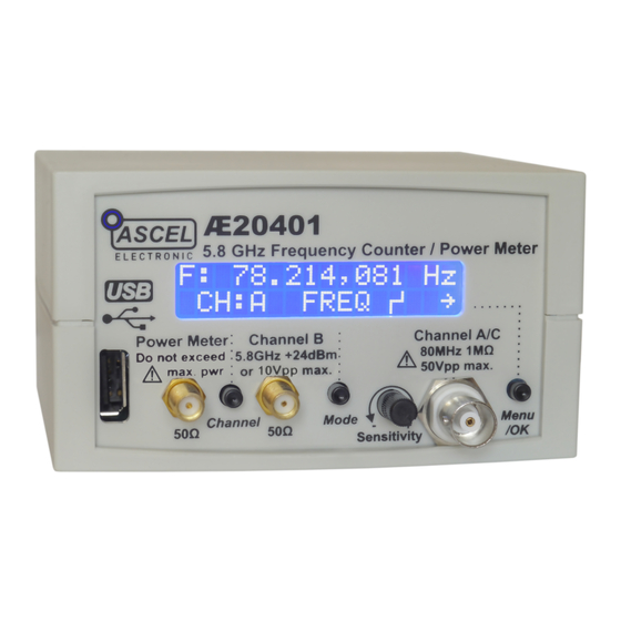
- Page 1 Æ20401 5.8 GHz Frequency Counter / Power Meter Assembly and Operation Manual REV 3.1 EN © 2015 Ascel Electronic...
-
Page 2: Table Of Contents
Table of Contents Safety Information..............ii Handover of a Device Built From a Kit........iv Intended Use................iv ESD Warning................v AE20401 5.8 GHz Frequency Counter / Power Meter....1 Circuit Description..............2 Soldering..................4 Component Reference..............6 Assembly..................14 Adjustment of the input amplifier..........18 Troubleshooting Checklist............20 Power Supply................22 Case Mounting.................23... -
Page 3: Safety Information
Warning Please read this manual before you assemble and use this kit. Keep it accessible for all users at all times. Safety Information Know and follow the applicable regulations for electric devices in your region. In Germany, these especially 0100, 0550/0551, VDE 0700, VDE 0711 and VDE 0860. - Page 4 •Always check if the device is suitable for the intended purpose before putting the unit in use. Seek assistance from a qualified professional or the manufacturer if you are not sure. • The manufacturer assumes no liability for errors made during assembly or operation.
-
Page 5: Handover Of A Device Built From A Kit
Handover of a Device Built From a Kit (in countries where applicable) If you hand over a device built from a kit, you legally become the manufacturer. This mean you are responsible for complying with the appropriate regulations for electronic devices. All accompanying papers, in particular this manual, must also be passed over. -
Page 6: Esd Warning
ESD Warning What is ESD? ESD (Electrostatic Dis- charge) is the sudden flow of electricity between two Warning symbol for an objects caused by contact electrostatic sensitive device or an electrical short. It can reach very high voltages of many kV. In some cases even over 100kV! Causes of ESD The main cause of ESD events is static electricity. -
Page 7: Ae20401 5.8 Ghz Frequency Counter / Power Meter
AE20401 5.8 GHz Frequency Counter / Power Meter The AE20401 combines three different functions: - A frequency counter, that range from mHz resolution with reciprocal counting algorithms to 5.8 GHz with the optional Channel B Module - A pulse counter (Channel C) -
Page 8: Circuit Description
Circuit Description The circuit diagram of the AE20401 can be divided into several parts, which are described here. The digital part is based on microcontroller IC1. IC1 controls all functions, computes the readings, and drives the LCD. The USB port is handled by the FT230X UART-USB Bridge (IC5). - Page 9 Now, all these signals are routed to a multiplexer (IC7), where three signals are available: the comparator output from Channel A, the divided-by-16 signal, and the divided-by-1000 signal from Channel B. The microcontroller selects one of these signals, depending on active channel and mode, which is processed to create a reading.
-
Page 10: Soldering
Soldering Please read the following pages if you are not yet experienced in soldering. Good soldering is a matter of practice! Practice on old boards until you feel confident before assembling the kit. • The parts are mounted on the silkscreen side of the PCB. Except parts whose designators ends with an asterisk (like S1*). - Page 11 • When soldering active components (ICs, Transistors, LEDs...), it is very important to prevent overheating the components. They should be soldered in no more than about 5 seconds. In addition, it is important not to confuse the polarity! See the next chapter on individual component types and their correct orientation.
-
Page 12: Component Reference
Component Reference 1 Resistors To save PCB space, the resistors are mounted standing. To install: 1. Bend the leads in form and put the resistor through the corresponding mounting holes. 2. Bend the leads aside to prevent the resistor from falling out. 3. - Page 13 Color Codes: Color Digit Multiplier Tolerance ± in % None Silver Gold Black Brown Orange Yellow Green Blue 0.25 Purple Grey 0.05 White 2 Capacitors / Electrolytic Capacitors Capacitors are soldered the same way as resistors. Electrolytic capacitors are polar. They must be mounted in the correct orientation! They will be destroyed when installed in reverse polarity and may even burst! Please keep in mind that different manufacturers mark the...
- Page 14 Capacitance Identification A three-digit number without letters is the capacitance in pF, where a are the first two digits calculated this way: a∗10 and b is the third digit (105 become 10*10 pF = 1µF). One- or two-digit numbers states the capacitance directly in pF. A number including the letter "n"...
- Page 15 3 Diodes The circular band on diodes identifies the cathode (negative terminal). The bar depicts the cathode in the symbol. The positive terminal is called the anode. Diodes are mounted horizontal. Try not to heat up the body of the diode while soldering. 4 LEDs LEDs (light-emitting diodes) must be soldered with respect to the correct polarity as well.
- Page 16 5 IC-Sockets / ICs With ICs (integrated circuits), it is essential to observe correct polarity. Most ICs will be damaged or destroyed when mounted incorrectly. The mark on the silkscreen must match the notch on top of the IC. Pin numbers are counted counter-clockwise, starting from the notch.
- Page 17 6 Transistors Transistors must be mounted in the correct orientation. The flat side of the transistor must match the correspondent side in the silkscreen drawing. The leads may not cross. Note: field-effect transistors (FETs) are extremely sensitive to ESD. 7 Crystal The polarity of the crystal is not relevant, but the bottom side of the package is conductive.
- Page 18 8 Inductors Inductors are soldered just like resistors. They also use similar color-coding, usually with four bands. The first two are the base value (see table below), the third is the multiplier to the base value and the fourth is the tolerance. The inductor value base value * multiplier [ ±...
- Page 19 9 Module Pin Headers The orientation of the pin headers is as follows: 10 Crystal oscillator / TCXO Module Unlike crystals, oscillators are polar. Pin 1 is identified by the pointy edge, the other edges are rounded. The TCXO Oscillator Module has the same size and pinout as a standard oscillator, with Pin 1 as the pointy edge.
-
Page 20: Assembly
Assembly General note It is essential to work precisely and systematically to minimize the possibility of faults. Check every step, each component placement and orientation, and any solder joint. Follow the assembly order given in the manual. Take your time - it takes longer to troubleshoot than to prevent faults by working accurately. - Page 21 Mounting 1. Solder all of the parts without an asterisk on the side of the board where the silkscreen is. (see the picture on the next page). Wait to insert IC1 in the socket until you have finished the assembly. After all the parts on this side are soldered, please examine the board carefully for shorts, bad solder joints and correct placement.
- Page 22 Installation of the modules Channel B / PWR (Power Meter) The modules are fully assembled and tested, they just have to be put on the appropriate pin header. The position of the socket is such that each module only fits on the correct header. Be careful not to put the module a row or column aside on the header - it may be damaged if the power is turned on then! The modules may be used with a case only!
- Page 23 Finished Component Side Finished Solder Side, without the LCD LCD Mounting...
-
Page 24: Adjustment Of The Input Amplifier
Adjustment of the input amplifier The Channel A/C input amplifier must be adjusted after the mounting is complete. The maximum sensitivity of the channel depends on an accurate adjustment. Please let the counter warm up for at least 30 minutes before performing the adjusting procedure! Required equipment: A signal source that produces a sine wave between 10 kHz and... - Page 25 Use the vertical adjustment control on the oscilloscope to adjust the signal until it is centered on the base line as shown in the picture. Without changing the vertical adjustment control, probe pin 2. You should see a small amplitude square wave as shown in blue in the picture.
-
Page 26: Troubleshooting Checklist
Troubleshooting Checklist Check and tick off every step. □ Is the polarity of the supply voltage correct? □ Is the supply voltage in the range of 8-12V when the device is turned on? □ Are all resistors placed right? Check the color bands. □... - Page 27 □ Are there solder bridges on the solder side of the PCB causing shorts? They are easier to find if you hold the PCB toward bright light. □ Are there bad/cold/dry solder joints? Jiggle component leads at the solder joint with a pair of tweezers. Re- solder them if any move.
-
Page 28: Power Supply
Power Supply An 8V-12V DC power supply capable of providing at least 300mA is required. The optional AC adapter, batteries or any other supply that meets these criteria can be used. Warning: An AC power supply may not be used! Note: It is advisable to use a current limiting lab power supply when switching on for the first time. -
Page 29: Case Mounting
Case Mounting Note: This describes the optional case available with the kit. The case is provided with all necessary cutouts and labels. 1. Put the extension caps on the tact switches. 2. Join the front panel and the PCB and insert both in the respective brackets. - Page 30 4. The highlighted bracket on the front side of the bottom case part should be broken off, as it will interfere with the optional modules. 5. Solder two pieces of wire, about 15cm (6") long, to the Cinch connector and its ground leads. 6.
-
Page 31: Operation
Operation Functions/Menu Structure... -
Page 32: Basic Operation
Basic Operation General Notes Signals may only be connected to one of the inputs or the EXT jack if the device is powered on! If a signal is applied and the device is off, damage to the input circuitry may occur, even if the signal is within the allowed limits for the particular input! Always disconnect all cables before switching the counter off. - Page 33 Power-on After the counter is switched on, it displays the installed modules. If an installed module is not shown, turn it off and check if the module is installed correctly. Channel select Press to change to the next Channel. Channel B and Channel PWR (Power Meter) are only available if the appropriate module is installed.
- Page 34 Menu To access the menu of each channel, press . Then press Menu/OK to switch between the menu items and to change Channel Mode the value of the selected menu items (some items leads to a submenu where a number can be entered or a function executed).
- Page 35 Entering numbers In some menus, a number must be entered, e.g. Offset Value or IMP/REV. The number is entered one digit after another, the active digit is blinking. Press to advance to the next digit Channel to increase the active digit by 1. "0" follows after "9". Mode To help enter the whole number at once, there is no overflow - if "00090"...
- Page 36 Channel A Sensitivity adjustment Channel A (and thereby also Channel C, as it shares the same input) has an adjustment control which allows lowering the input's sensitivity. This may be necessary if the input signal is noisy or is superimposed by another signal that has a greater amplitude than the sensitivity of the input.
- Page 37 Example 1: noise Example 2: one signal superimposed on another...
- Page 38 Display Annunciators Modes The available modes are Frequency ( [f ] ), Period ( FREQ [T ] ) where: T = and Revolutions Per Minute ( RPM= ∗60 , Ip is the adjustable [RPM ] ), where: number of pulses per revolution. Menu Functions Smooth [on/off] active in mode: FREQ, PER...
- Page 39 Offset(/Scale) [on/off] active in mode: FREQ The Offset/Scale function provides a means of multiplying the measured value by an entered scaling factor and then adds or subtracts another entered value. The result is then displayed: =(f ∗SCALE )+ VALUE display To use the Offset/Scale function, activate this menu item and enter the values for SCALE and VALUE in the next menu items.
- Page 40 IMP/REV active in mode: RPM This adjustment allows selecting the number of pulses per one revolution, it is then used to calculate RPM. With this, the rpm output of rotary encoders/sensors that outputs multiple pulses per revolution can be measured. D(ecimal) Point ["."...
- Page 41 Channel B The operation of Channel B is virtually identical to Channel A. Please pay attention to the maximum input voltage! Modes The available modes are Frequency ( [f ] ) and Period FREQ [T ] ) where: T = Menu Functions Smooth [on/off] active in mode: FREQ, PER...
- Page 42 Channel C (Pulse Counter) Selecting Channel C allows using Channel A as a pulse counter, instead of measuring the frequency. Start/Stop of the counter can be controlled on the device itself ( SOURCE: ), using the external input jack ( ) and also BUTTON SOURCE: EXT...
- Page 43 Menu Functions RESET Reset the counter value back to zero. IMP/COUNT The number of pulses that are recognized as one "count" can be adjusted. E.g. if a moving part hits the limit switches 2x per movement and the number of movements should be counted, set IMP/COUNT to 2, the counter will count up every 2 pulses.
- Page 44 Channel PWR (Power Meter) The Channel PWR Module turns the AE20401 into a Power Meter capable of measuring the power of signals from DC to 500 MHz / 10 MHz to 8 GHz in the range of -55 dBm to +30 / -5 dBm.
- Page 45 Menu Functions EXT(ernal) ATT(enuator) [on/off] Set this to on, if an external attenuator is connected, and enter its value in the next menu item. This value will then be added to the measurement. A small indicates that this function is EXT ATT [VALUE] The value of the external attenuator can be entered here in dB.
- Page 46 D(ecimal) Point ["." / ","] Identical to Channel A PWR CAL(ibration) Starts the Power Meter calibration routine. See the appropriate chapter on how to perform the calibration. Calibration By performing the calibration routine using precise standards, the accuracy of the time base and the Power Meter can be increased further.
- Page 47 Manual Offset Press Input the offset value. The value is entered in 0.1 Channel. ppm increments. Positive and negative values are accepted. With a 10 MHz input signal, +0.1 ppm causes a change of 1 Hz. Press to save and leave the calibration routine. Menu/OK Automatic Calibration with 10 MHz Reference Press...
- Page 48 and press . During calibration, "CALIBRATION..." Menu/OK shown. Next, is shown, change the signal to "CONNECT xx dBm" 1 MHz, +10 dBm (AE204015) or 10 MHz, -10 dBm (AE204014). If no valid signal was recognized or the signal is outside of the max limits for calibration, "CAL ERROR, VALUE will be shown, otherwise NOT SAVED!"...
-
Page 49: Firmware Update
Reset to Defaults Most settings, such as Offset Value/Scale, IMP/REV or Ext. Att. Value, as well as the calibration values are saved permanently and remain available after the counter is powered off and on again. To clear all saved values and reset to defaults, press and hold while switching the counter on. -
Page 50: Circuit Diagram
Circuit Diagram Part 1/2... - Page 51 Part 2/2...
-
Page 52: Bill Of Materials
Bill of Materials Quantity Parts(s) Value / Description C3, C4, C6, 100nF C11, C12, C16 100pF Ceramic 100pF Film 100nF Film 10µF Electrolytic 100µF Electrolytic 220µF Electrolytic R1, R11, R19, 1KΩ R20, R21 100KΩ 2W 100Ω 910KΩ 20KΩ R6, R10 220Ω... - Page 53 47KΩ IC Socket 28 pin / Microcontroller 74ACT74 Quad Flip-Flop 74HC393 Dual 4-bit Counter 7805 Voltage Regulator LT1016 Comparator 74HC153 Multiplexer LT1460 2.5V Reference ALPS Potentiometer 10K Trimmer 200Ω 1N4007 Diode D2, D3, D4, D5 1N4148 Diode BF256A JFET Cinch Connector Power Connector BNC* BNC Connector...
- Page 54 USB Models only: FT230X USB UART Interface (pre-assembled) C7, C17 100nF C9, C14 47pF R7, R13 27Ω 10µF Electrolytic USB* USB Type "A" Connector Other: - PCB - 4 spacer bolts and 8 M2.5 screws for LCD mounting - Modules (optional) - Case and 3 extension caps for the tact switches (optional) - AC adapter (optional) Note: Parts whose designator contains an asterisk are mounted on the opposite...
-
Page 55: Component Placement Diagram
Component Placement Diagram Note: Parts whose designator contains an asterisk are mounted on the opposite side of the PCB. See the chapter "Assembly" for details. Note: To help locate the right elements, parts and their respective designators are highlighted in the same color. Scale in mm. -
Page 56: Data Interface
Data Interface The AE20401 frequency counter optionally comes with an USB interface which can be used to control all of its functions and read out the measured values. The USB driver creates a virtual serial (COM) port. This makes integration with external tools and applications very easy. -
Page 57: Usb Driver Installation
USB Driver Installation The driver for the virtual serial port must be installed before the software can be used. Drivers for all supported operating systems are included with the device., They can be found in the "Driver" directory on the CD. Note: Newer Windows OS (starting with Windows 7) can install the driver automatically if an Internet connection is present. - Page 58 Software Screenshot Software Operation First, select the COM port the counter is connected to click "Open". The connection will be established. The display shows the values in a similar manner as the counter's display. Press one of the buttons to change the channel. The controls assigned to this channel will be activated, the functions are identical to direct control on the device.
-
Page 59: Specifications
Specifications Channel A: Frequency Range: 2 Hz - 80 MHz Modes: Frequency, Period, RPM Pulse/Revolution (RPM): adjustable Functions: Offset, Smooth, Trigger Edge Sensitivity: 1 MHz: 50 mV 50 MHz: 100 mV Sine wave, in Vrms Impedance: 1 MΩ Coupling: Attenuation: adjustable Max. - Page 60 1 GHz: -20 dBm 3 GHz: -15 dBm 5 GHz: -5 dBm Impedance: 50 Ω Coupling: Max. Input Voltage: +24 dBm (10 Vpp) Input: Time Base: Accuracy (Standard): 50 ppm Accuracy (TCXO Option): 1 ppm Calibratable: Channel C (Pulse Counter): Frequency Range: 2 Hz - 5 MHz (50% duty) Sensitivity:...
- Page 61 Channel PWR (Power Meter): Modes: dBm, mW, Vrms, Vp, Vpp Functions: External Attenuator Impedance: 50 Ω Resolution: 0.1 dBm Calibratable: Input: AE204015: Frequency Range: DC - 500 MHz Range: -55 dBm - +30 dBm Max Power: +32 dBm AE204014: Frequency Range: 10 MHz - 8 GHz Range: -55 dBm - -5 dBm...
-
Page 62: None
Data Format Format: <ECN>:<CODE>:<DATA>:; <ECN> 401 – Device Identification Number. It is always 401 for this device. Example: 401:F:0:; Set Channel A Mode to FREQ Code DIR Function Value (DATA) → Frequency Channel A in nHz* → Frequency Channel B in uHz* →... - Page 63 *Nr of valid counts depends on range...
- Page 64 ASCEL ELECTRONIC - www.ascel-electronic.de - 2015...
Need help?
Do you have a question about the AE20401 and is the answer not in the manual?
Questions and answers