APsystems ECU-3 Installation And User Manual
V4 energy communication unit (ecu)
Hide thumbs
Also See for ECU-3:
- Installation and user manual (33 pages) ,
- Installation & user manual (41 pages)

Related Manuals for APsystems ECU-3


Summary of Contents for APsystems ECU-3
- Page 1 Installation / User Manual APsystems ECU-3 (V4) Energy Communication Unit(ECU) Rev 1.1 © All Rights Reserved...
-
Page 2: Table Of Contents
Real-time Data Screen ....................20 Administration Screen....................22 Remote ECU Management (EMA)................30 ECU Configuration/ECU Status Page ................31 Setting the ECU Time Zone.................... 32 Managing Inverter IDs and Updating the Inverter ID List ..........32 Technical Data ......................34 APsystems ECU-3 V4 Installation/User Manual... -
Page 3: Introduction
Internet database in real time, requiring only a single data and power cable. Through the APsystems Monitor software, the APsystems Communicator gives you precise analysis of each microinverter and module in your solar installation from any web-connected device. -
Page 4: Interface Explanation
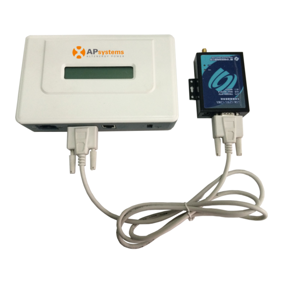
RS232 Serial Port You can connect GPRS module to RS232 serial port, select GPRS module to connect to the network on “Network Connectivity” page, and communicate with the EMA, to check the system data. Figure 4 APsystems ECU-3 V4 Installation/User Manual... -
Page 5: Network Port
Ethernet network port. USB Interface USB interface is reserved. Reset Press the “Reset” button for three seconds or longer, ECU will automatically return to the default settings. NOTE: The historical power generation won't be cleared. APsystems ECU-3 V4 Installation/User Manual... -
Page 6: Hardware Installation
A broadband router with either a CAT5 Ethernet, or wireless router is available for your use. A laptop with a web browser (to view the APsystems EMA online monitoring application). A pre-programmed ECU. Selecting an Installation Location for the ECU ... - Page 7 Doing so allows the ECU to automatically update its internal software while the rest of the physical installation is underway. The ECU will then communicate with the inverters when the installation is complete and the array is energized. APsystems ECU-3 V4 Installation/User Manual...
-
Page 8: Cable Connections
ECU. 2) Connect the LAN cable into a spare port on the broadband router. Figure 9 Option 2: Wireless Connection. Use ECU internal WLAN (see Managing the WLAN connection pg. 25). APsystems ECU-3 V4 Installation/User Manual... - Page 9 1. A PLC bridge uses the power line to communicate and requires both a “send” and “receive” unit. 2. The quality and length of LAN cable will affect the ECU communication quality. You can use a Switch to enhance the communication quality if necessary. APsystems ECU-3 V4 Installation/User Manual...
-
Page 10: Power Up Ecu
ECU power cord Figure 11 WARNING: Do NOT plug the ECU into a power strip, surge protector, or uninterruptable power supply (UPS). The surge suppression and/or filtering on these sorts of devices will substantially diminish PLC performance. APsystems ECU-3 V4 Installation/User Manual... -
Page 11: Ecu Initialization Sequence
“192.168.131.228”, the ECU-router connection has not been successful, in which case you’ll need to check all of the cabling connections and reboot the ECU by removing the power cable for a few seconds and reconnecting. APsystems ECU-3 V4 Installation/User Manual... - Page 12 EMA Communication: A “+W” indicates that the ECU is communicating with the APsystems EMA via the Internet. “-W” is an indication that there is a problem and the ECU is not communicating with the APsystems EMA. Need to setup the security authority to offer Auto IP configuration.
-
Page 13: Step 2: Ecu Time Zone Setting
Date, Time Zone management in p.25. Step 3: EMA Monitoring After ECU display “+W”,contact installers or APsystems technical staffs in your local area and they will setup an EMA account with User Name and Password, then complete EMA management(see pg.28). -
Page 14: Basic Operation
Basic Operation The APsystems ECU has one two-line, 40-character LCD display with alphanumeric. Set the mode using a single button. NOTE: ECU functions as a gateway and monitors the microinverters that are connected to the PV modules. Therefore, the communication between inverters and ECU does not affect inverters' performance, even if ECU drops inverters. -
Page 15: Restore The Factory Set Operation
NOTE: The above operation should be done under the guidance of technicist. Restore the factory set operation The following diagram guides to the connectors back of APsystems ECU. Figure 21 RESET For the ECU restoring the factory set, simply press the “Reset”... -
Page 16: Troubleshooting
Service Provider or refer to your router documentation for troubleshooting assistance. LCD Displays “-W”: The ECU could not connect to the APsystems website. Check network connectivity to the router. You may need to contact your Internet Service Provider or refer to your router documentation for troubleshooting assistance. -
Page 17: Local Network Interface
Select “Use the Following IP Address” radial button and the enter IP Address and Subnet Mask as listed below. Do not enter anything in the DNS Server address section. IP Address: 192.168.131.1 Subnet Mask: 255.255.255.0 APsystems ECU-3 V4 Installation/User Manual... - Page 18 Select “Apply”. 10. Using a standard web browser on your computer, enter the lan IP address that is displayed on your ECU in to the URL search field. The ECU’s “splash” screen is displayed . APsystems ECU-3 V4 Installation/User Manual...
-
Page 19: Connecting To The Ecu Via The Wi-Fi Hotspot
The first connection have no password. Using a standard web browser on your computer, enter the wireless IP address that is displayed on your ECU into the URL search field. The ECU’s “splash” screen is displayed. Figure 23 APsystems ECU-3 V4 Installation/User Manual... -
Page 20: Home Screen
ECU Eth0 Mac Address Address of ECU’s LAN. ECU Wlan0 Mac Address Address” of the ECU’s internal WLAN. Inverter Comm. Signal Level The communication strength between inverters and ECU. The range is 1-5, the higher the better. APsystems ECU-3 V4 Installation/User Manual... -
Page 21: Real-Time Data Screen
To view the system power of any period, click "Power" at the real-time data page. The Trend of system power screen is displayed. Figure 26 c) Power generation statistics Press “Energy” at the real-time data page to view the system power generation of your solar array . APsystems ECU-3 V4 Installation/User Manual... - Page 22 Local Network Interface The Power generation statistics screen is displayed. Power generation statistic of current week. Figure 27 Power generation statistic of current month. Figure 28 Power generation statistic of current year. Figure 29 APsystems ECU-3 V4 Installation/User Manual...
-
Page 23: Administration Screen
If the number of inverter ID displayed on the page is less than the actual number of inverters installed. 1) Select “Administration” at the top of the page. The ID Management page with the existing inverter IDs is displayed. APsystems ECU-3 V4 Installation/User Manual... - Page 24 If the number of inverter ID displayed on the page is more than the actual number of inverters installed. 1) Select “Administration” at the top of the page. The ID Management page with the existing inverter IDs is displayed. Figure 32 Figure 33 APsystems ECU-3 V4 Installation/User Manual...
- Page 25 ID installed, please modified the wrong inverters ID from “Input Inverter ID” section, then click “Update”. And “ID updated successfully !” will displayed after few seconds. The ID Management page with the existing inverter IDs is displayed. Figure 34 Figure 35 APsystems ECU-3 V4 Installation/User Manual...
- Page 26 Add the new inverter, and Delete the old one. Remember to follow up with the same process on the APsystems EMA because the ECU and EMA need to be in sync with each other. b) Changing the Date, Time Zone It is critical for accurate power production reporting that the ECU is programmed with the correct date, time, and time zone.
- Page 27 The ECU can be assigned a static IP Address if the network design requires it. 1) Select “Administration” at the top of the page. 2) Select “Network Connectivity”. The Network Connectivity page is displayed. APsystems ECU-3 V4 Installation/User Manual...
- Page 28 PC can connect to ECU to access local web. ECU works in hotspot mode by default. Change to Wlan mode Select “Administration” at the top of the page. Select “WLAN”, and click “WLAN” tab. Open WLAN, selsct “OK”. Figure 40 APsystems ECU-3 V4 Installation/User Manual...
- Page 29 If ECU has connected to route, it will display the SSID and IP address. Now you can connect PC and phone to the route, enter the ECU’s IP (e.g., 192.168.1.112) into browser to access the local web. Figure 42 APsystems ECU-3 V4 Installation/User Manual...
- Page 30 The Hospot Connectivity page is displayed. Figure 43 f) Firmware Update Select ECU upgrade package, and click OK to upgrade ECU firmware. Upgrade package can be downloaded at www.APsystems.com. Figure 44 APsystems ECU-3 V4 Installation/User Manual...
-
Page 31: Remote Ecu Management (Ema)
Remote ECU Management (EMA) The ECU has been design with remote connect functionality. You can access this remote functionality through the APsystems Energy Monitoring & Analysis (EMA) website, using your installer login credentials. Changes made remotely through the EMA do not take affect until the ECU’s next reporting cycle. -
Page 32: Ecu Configuration/Ecu Status Page
ECU will not be able to collect data from the inverters. Update Inverter ID list If an inverter(s) is added or swapped for a new unit, then the ECU’s programmed list of inverters will need to be updated. APsystems ECU-3 V4 Installation/User Manual... -
Page 33: Setting The Ecu Time Zone
Press “Send”. Managing Inverter IDs and Updating the Inverter ID List 1) Select the “ECU SETTING” tab. 2) Select the “Inverter Links” tab. The Inverter Links Configuration page is displayed Inverter Links Figure 48 APsystems ECU-3 V4 Installation/User Manual... - Page 34 1) Log onto EMA App. 2) Scan the inverter IDs. Delete IDs from Inverter List 1) Select “Delete” in Operation Selection. 2) Enter all of the inverters to be removed from the Inverter ID Field. 3) Press “Sent”. APsystems ECU-3 V4 Installation/User Manual...
-
Page 35: Technical Data
ICES-003, AS NZS 60950-1, GB/T17799 Specifications subject to change without notice - Please ensure you are using the most recent update found at www.APsystems.com. This device complies with part 15 of the FCC Rules. Operation is subject to the following two conditions: (1) This device may... - Page 36 For more detailed information about disposal of your old appliance, please contact your city office, waste disposal service or the shop where you purchased the product. APsystems ECU-3 V4 Installation/User Manual...
Need help?
Do you have a question about the ECU-3 and is the answer not in the manual?
Questions and answers
my ecu-3 lost communication how do I hook it back up