
Related Manuals for Qel QIRF


Summary of Contents for Qel QIRF
- Page 1 QIRF REFRIGERANT GAS TRANSMITTER/SENSOR INSTALLATION OPERATION AND MAINTENANCE MANUAL...
-
Page 2: Table Of Contents
QIRF Operation And Maintenance Manual Table Of Contents READ BEFORE OPERATING ........................3 GENERAL INFORMATION ......................3 ........................3 RINCIPLE OF PERATION ..........................4 EATURES ............................4 PPLICATIONS ..........................5 PECIFICATIONS INSTALLATION ..........................7 ..........................7 ENSOR OCATION ........................7 HYSICAL IMENSIONS ..........................8 AMPLING ......................8 OUNTING AND YSTEM IRING 2.4.1... - Page 3 QIRF Operation And Maintenance Manual DVM C 4-20 ................29 ONNECTION FOR MEASUREMENT ..................29 UTPUT ALIBRATION TROUBLESHOOTING ........................30 QIRF Operation Manual May. 01, 2012 85050-301-000 Rev C...
-
Page 4: Read Before Operating
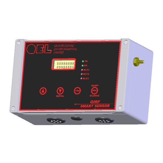
However, our QIRF smart sensor modules do it better, faster, and more precisely. The QIRF smart sensors are entirely electronic with no moving parts, and are built around our unique QT Gas Sample Cell with constant temperature control integrated with IR Source and IR Detector together. -
Page 5: Key Features
• 3 Relay Status LED, TX Status LED and RX Status LED • CSA/UL approval (pending) 1.3 Applications The QIRF is designed to monitor for the loss of refrigerant gas in a variety of applications: • Mechanical equipment rooms • Propellant filling operations •... -
Page 6: Specifications
QIRF Operation And Maintenance Manual 1.4 Specifications 24VDC nominal, range 18 to 30VDC, 1.0A DC Total Max. Input Power: 24VAC nominal, range 15 to 24VAC, 1.0A AC Total Max. F1 on Display Board: Polyswitch 1.6A Fuse: F2 on Display Board: Polyswitch 50mA... - Page 7 QIRF Operation And Maintenance Manual Output Signal: RS-485 with OptoMux protocol • Available Controller: M-Controller Q4 Controller RS-485 with ModBus protocol 4-20mA or 2-10VDC Analog Signal IP 66 & NEMA 4, 4X, 12 & 13 Enclosure Rating: Cover Screws should be torqued to 2.5lbs-in (30cN-m) Operating Temperature: -45°C to 65°C...
-
Page 8: Installation
QIRF Operation And Maintenance Manual 2. Installation 2.1 Sensor Location Several factors should be considered when selecting locations to install sensors. The following general suggestions should be considered to assure the detection of the target gas. Select the most suitable location for each sensor. -
Page 9: Gas Sampling
QIRF Operation And Maintenance Manual 2.3 Gas Sampling In Diffusion version QIRF, the gas sampling system is composed of a diffusion type gas sample chamber and two vent holes on the enclosure bottom. The gas flows in and out through the two vent plugs on the bottom of the QIRF enclosure. See above picture. -
Page 10: Terminals
QIRF Operation And Maintenance Manual 2.4.1 Terminals Display Board Terminals 2.4.2 Power Supply NOTICE: Installing or using this equipment in a manner not specified by the manufacturer could cause electric shock, bodily injury, or risk of fire. Power Supply: Voltage:... -
Page 11: Wire And Cable
Longer runs may require the terminating resistors. But adding terminator dramatically increases power consumption. Factory default setting is disabled terminator. The QIRF smart sensor supplies this resistor on the display board, and it is chosen using a jumper at J3. • J3 1-2: Terminator Disabled / OFF (default) •... -
Page 12: Rs-485 Driver Replacement
The maximum output impedance is 600 ohms for 4-20mA output. The maximum output current is 10 mA for 2-10VDC output. Test point SIG+ and SIG- are used to measure the current online when the QIRF is working in the field. -
Page 13: Relays Output
QIRF Operation And Maintenance Manual 2.4.8 Relays Output QIRF is equipped with three programmable Single-Pole Double-Throw (SPDT) Relays on board, which is able to make it work alone to control other equipment, such as fans, lights, horns, or visual alarm indicators in different applications. -
Page 14: Function And Configuration
Note: No adjustments or calibration should be performed within 24 hours. 3.3 Keypad QIRF has four keys on the front panel. To access the keypad, the magnet tool in the product-shipping package is needed. • Key [Up]: Scroll and Hold •... - Page 15 Hold 3 seconds? Latched Satus Hush all Buzzers in Alarm Status Is ENTER key? PASSWORD Hold 3 seconds? > NNNN ENTER Passoword is Correct? MENU MODE QIRF Running Mode Key Functions Flow Chart QIRF Operation Manual May. 01, 2012 85050-301-000 Rev C...
-
Page 16: Status Led
3.4 Status LED 3.4.1 RS485-TX/RX: When the QIRF is connected to a Controller System through RS-485, the traffic of the communication can be monitored visually through the two RS-485 indicators. One is RX LED, which indicates the data stream received in the Controller. The other is TX LED, which indicates the data stream out of the QIRF. - Page 17 QIRF Operation And Maintenance Manual MENU MODE MENU MODE MENU MODE MENU MODE Down 1_ SYSTEM SYSTEM SETTING SETTING SUBDIVISION SEE SYSTEM SETTING Page Down 2_ ZERO ZEROING? S3 R134a ACCEPTED NN PPM ZERO... Down 3_ SPAN SPAN CAL? S3 R134a...
-
Page 18: Menu "1_System Setting
QIRF Operation And Maintenance Manual 3.8 Menu “1_System Setting” System Setting Subdivision contains general settings for monitor operations, communications and 4-20mA calibrations. RETURN TO UP LEVEL PRESS KEY UP AND KEY DOWN TO MODIFY Down ADDRESS NEW ADDR ACCEPTED >... -
Page 19: System Settings
Address: Q4 Controller supports RS-485 addressing from 0 to 3 for digital sensor. The QIRF smart sensor RS-485 address can be defined from 0 to 255 to be used in RS-485 OptoMux or ModBus communication. Default address is Define Baud Rate for RS-485 OptoMux or ModBus Communication. - Page 20 Gas Type and Measurement Unit that are defined for the channel in M-Controller. AutoZero: QIRF is two channel detector, it’s designed to work in the situation where the Auto Zero function is not suitable. So QIRF discards AutoZero setting, QIRF will never do auto zero in background.
-
Page 21: Menu "2_Zeroing Calibration
All units are factory calibrated. The QIRF uses full scale as its CAL GAS concentration: Basically, QIRF full scale for all Refrigerant gases is 1000ppm except for R123, which is 100ppm. Gas Type... - Page 22 QIRF Operation And Maintenance Manual • For Diffusion Version: Connect the zero gas supply tubing to the fitting on the right side of enclosure • For Pump-through Version: Connect the zero gas supply tubing to the push-in fitting on the bottom side of enclosure 2.
-
Page 23: Menu "3_Span Calibration
QIRF Operation And Maintenance Manual 3.10 Menu “3_Span Calibration” 3_ SPAN SPAN CAL? S3 R134a ACCEPTED NN PPM CAL... Span Calibration Flow Chart 3.10.1 Span Calibration Procedure 1. Connect tubing to QIRF • For Diffusion Version: Connect the cal gas supply tubing to the fitting on the right side of enclosure •... -
Page 24: Menu "4_Output Testing
QIRF Operation And Maintenance Manual 3.11 Menu “4_Output Testing” For system installation testing, it is necessary to force relay and buzzer actions. Enter this branch as shown in the flow diagram. The Relay Testing feature allows the user to force actuation on each relay. This function forces an Actuate vs. -
Page 25: Menu "6_Relay Database
QIRF Operation And Maintenance Manual 3.13 Menu “6_Relay Database” 3.13.1 Relay Configurations Each relay may be individually set to be enabled or disabled. If it’s Enabled: disabled, the relay is always de-actuate no matter what’s the current gas concentration. Default is Enabled. - Page 26 QIRF Operation And Maintenance Manual Defaults for R123 100ppm: • Relay1 Action On / Off: 50 / 45 ppm • Relay2 Action On / Off: 75 / 70 ppm • Relay3 Action On / Off: 100 / 95 ppm “Delay on Actuation” or “Delay on Make”. For each relay a separate time...
-
Page 27: Relay Database Flow Chart
QIRF Operation And Maintenance Manual 3.13.2 Relay Database Flow Chart CHOOSE A RELAY TO MODIFY MODIFY MODIFY MODIFY RETURN Down Down TO UP LEVEL RELAY1? RELAY2 RELAY3 RELAY1? RELAY1? FINISHED Down ENABLED DISABLED 1.NORMAL 2.NORMAL Down ENERGIZE DE-ENERGIZE 1. WITH 2. -
Page 28: Menu "7_A-Out Database
QIRF will compare the concentration at 4mA and the concentration at 20mA, you may assign a larger concentration for 4.0 milliamps than for 20 milliamps; the QIRF will still stretch a straight line signal between the two points and then convert the current gas reading to analog output. -
Page 29: Menu "8_Buzzer Database
(e.g.: the travel of the valve, fan speed, relay set points, etc. can be verified.) Any concentration between 0ppm and 9999ppm can be simulated. Default is “Simu Disabled” when the unit is powered up. 4. MODBUS Protocol Supported By QIRF For ModBus protocol, please contact QEL. QIRF Operation Manual May. 01, 2012... -
Page 30: Maintenance
5. Maintenance 5.1 DVM Connection for 4-20mA measurement • QIRF is Offline of the 4-20mA loop: o Switch DVM to measure DC current, plug the probe “-“ into GND and plug the probe “+” into SIG- on the Display Board. -
Page 31: Troubleshooting
QIRF Operation And Maintenance Manual 6. Troubleshooting This troubleshooting guide is intended as an aid in identifying the cause of unexpected behavior and determining whether the behavior is due to normal operation or an internal or external problem. SYMPTOMS PROBABLE CAUSE... - Page 32 This warranty is in lieu of all other warranties, expressed or implied, and no representative or person is authorized to represent or assume for QEL any liability in connection with the sales of our products other than that set forth herein.
Need help?
Do you have a question about the QIRF and is the answer not in the manual?
Questions and answers